close control air conditioners - Thermo Control
close control air conditioners - Thermo Control
close control air conditioners - Thermo Control

You also want an ePaper? Increase the reach of your titles
YUMPU automatically turns print PDFs into web optimized ePapers that Google loves.
CLOSE CONTROL<br />
<strong>air</strong> <strong>conditioners</strong><br />
TECNAIR LV<br />
CLOSE CONTROL AIR CONDITIONERS
“The future has an<br />
ancient heart”<br />
CARLO LEVI
TECNAIR LV<br />
CLOSE CONTROL AIR CONDITIONERS
Contents<br />
1. Design choices<br />
for maximum energy saving pag. 6<br />
2. Characteristics and accessories pag. 9<br />
3. Free Cooling system pag. 10<br />
4. Two Sources system pag. 12<br />
5. P Series:<br />
Air <strong>conditioners</strong> for <strong>close</strong> <strong>control</strong> pag. 14<br />
6. G Series: Air <strong>conditioners</strong> for large data centres:<br />
perimetral installation pag. 18<br />
7. R Series: Air <strong>conditioners</strong> for large data centers:<br />
in-row installation pag. 22<br />
8. ACC Series:<br />
Axial fan <strong>air</strong> cooled condensers pag. 26<br />
9. Our solution for Data Center pag. 28<br />
GOST certification<br />
ISO 9001<br />
Cert. n° 273<br />
5
1. Design choices<br />
for maximum energy saving<br />
EDC ompressor<br />
Inverter Inverter Driven Driven<br />
Technology<br />
Technology<br />
BRUSHLESS DC COMPRESSORS<br />
WITH INVERTER TECHNOLOGY<br />
Thanks to the innovative BRUSHLESS DC technology<br />
with inverter, the compressors in the <strong>close</strong> <strong>control</strong> <strong>air</strong><br />
<strong>conditioners</strong> can:<br />
■<br />
■<br />
■<br />
■<br />
Maintain the thermo-hygrometric conditions of the <strong>control</strong>led<br />
areas at a constant level, guaranteeing that the set-point is<br />
respected even under partial load.<br />
Modulate the cooling capacity of the units between 20% and<br />
100% of the maximum capacity.<br />
Reduce the annual energy consumption of the unit by up to<br />
70% compared to a unit with ON-OFF compressors, thus<br />
obtaining a great increase in energy efficiency (EER) in that the<br />
power drawn by a BRUSHLESS DC compressor driven by<br />
inverter unlike other <strong>control</strong> systems which do not reduce the<br />
number of revolutions of the compressor, reduces in proportion<br />
to the decrease in cooling capacity supplied.<br />
Increase the safety of the plant thanks to the innovative design<br />
of the compressors which permits the perfect return of oil even<br />
at minimum speeds.<br />
EEValve<br />
Electronic Electronic Expansion Valve<br />
Expansion Valve<br />
EEV ELECTRONIC EXPANSION VALVE<br />
Guarantees, compared to the traditional TEV, an annual<br />
energy saving of 25% thanks to:<br />
■<br />
■<br />
Management of the lowest stable gas overheating value at the<br />
coil outlet, thus optimizing its heat transfer.<br />
The possibility, in winter or at night, of letting the condensing<br />
temperature decrease to 35°C with a great reduction in the<br />
compression ratio of the cooling cycle and therefore of the<br />
power draw.<br />
6
ECFan<br />
Variable Variable Air Flow Air Flow<br />
LATEST-GENERATION ELECTRONICALLY<br />
CONTROLLED FANS<br />
The use of composite materials for the impeller and<br />
fan motors with latest-generation BRUSHLESS EC<br />
ELECTRONIC MOTORS has enabled very large increases<br />
in performance levels, such as:<br />
■<br />
■<br />
■<br />
Power draw reduction by over 25% compared to traditional<br />
units with AC technology. Power draw is also reduced by about<br />
15% compared to the preceding generation of EC fans.<br />
Noise level reduction by over 5 dB(A) at partial loads.<br />
Thanks to integration with the powerful <strong>control</strong> algorithm, the EC<br />
fans can be regulated to guarantee the following:<br />
1. Ulterior energy savings of over 50% at partial loads by<br />
reducing the speed of the fans as the cooling capacity<br />
requirement decreases.<br />
2. Constant revolution number.<br />
3. Constant <strong>air</strong> quantity with real-time <strong>control</strong> through differential<br />
pressure sensors. Optimal <strong>control</strong> if F7 filters are installed.<br />
4. Constant pressure in the raised floor in order to optimise <strong>air</strong><br />
distribution in latest-generation data centers.<br />
ECFan<br />
Variable Variable Air Flow Air Flow<br />
ELECTRONIC FANS IN THE ACC AIR COOLED<br />
CONDENSERS<br />
Using fan motors with BRUSHLESS ELECTRONIC EC<br />
motors also in the <strong>air</strong> cooled condensers permits:<br />
■<br />
■<br />
■<br />
Energy saving, at partial loads, of over 45% compared to a<br />
normal AC motor.<br />
Noise level reduction of over 10% of a normal AC fan.<br />
Wide modulation range, making it possible, when external<br />
conditions permit, to manage very low condensing temperature<br />
set-points (35°C) in order to guarantee operation at high<br />
summer temperatures (T cond. 60°C).<br />
7
1. Design choices<br />
for maximum energy saving<br />
ECSurvey<br />
Next Generation <strong>Control</strong>ler<br />
Next Generation <strong>Control</strong>ler<br />
SURVEY MICROPROCESSOR<br />
Thanks to constant efforts in the research and development<br />
of <strong>control</strong> processes, the <strong>close</strong> <strong>control</strong> <strong>air</strong> <strong>conditioners</strong><br />
have one of the most advanced microprocessors available.<br />
It is capable of:<br />
■<br />
■<br />
■<br />
■<br />
Managing all the thermo-hygrometric requirements with PID<br />
algorithms with AMBIENT AUTOTUNING function.<br />
Managing, in an integrated manner, the operation of the EEV<br />
valve and the DC inverter with verification of the envelope of the<br />
compressors.<br />
Presenting a graphic display of temperature and humidity, daily<br />
and weekly.<br />
Permitting the user a high degree of supervision of the general<br />
functioning of the plant.<br />
They can also be equipped with:<br />
■<br />
■<br />
■<br />
FULL GRAFIC interface, with interactive icons and progress bars<br />
to make the <strong>control</strong>ler USER FRIENDLY even for those who are<br />
not familiar with <strong>air</strong> conditioning equipment.<br />
TOUCH SCREEN user terminal (accessory) for easy access to<br />
function parameters.<br />
Free supervision software for Windows, which enables<br />
supervision and recording of all operational parameters of<br />
the unit.<br />
Free Cooling<br />
Green Green<br />
Energy Energy Technology Technology<br />
FREE COOLING UNIT:<br />
RENEWABLE GREEN ENERGY<br />
Market attention to renewable sources of energy has<br />
encouraged the development of very low environmental<br />
impact units with FREE COOLING function.<br />
■ The innovative <strong>control</strong> algorithm and careful development of<br />
components in the unit permit energy savings of over 50% to be<br />
made compared to a normal direct expansion unit.<br />
■ The AUTOADAPTIVE SETPOINT function in addition enables the<br />
regulation of the dry cooler fans serving the unit to obtain always<br />
the best set-point of the water temperature as the external<br />
temperature changes. This regulation also permits the energy<br />
saving to be increased by making the fans function at partial load<br />
for most of the time.<br />
8
2. Construction<br />
characteristics<br />
■<br />
■<br />
■<br />
■<br />
■<br />
■<br />
■<br />
Certified performance<br />
Very high EER (Energy Efficiency Ratio).<br />
Very limited footprint.<br />
Very quiet operation.<br />
Complete frontal maintenance access if<br />
several machines are positioned side by side<br />
(only for the models highlighted in the<br />
performance table).<br />
Dark grey metal structure on wheels for easy<br />
positioning.<br />
Fire-resistant class 1 thermo-acoustic<br />
insulation panels.<br />
■ Scroll EC compressors with brushless<br />
motors for R410A with inverter for the cooling<br />
capacity modulation.<br />
■<br />
■<br />
■<br />
EEV: electronic expansion valve.<br />
Two- or three-way modulating valve to<br />
regulate cooling capacity of units with chilled<br />
water coils.<br />
Electrical panel equipped with all regulation<br />
and safety devices in compliance with EU<br />
■<br />
■<br />
■<br />
and International Regulations. For units<br />
with compressors a phase <strong>control</strong>ler is<br />
forecast too.<br />
EC (electronically commutated) fan motors<br />
which can be regulated according to three<br />
different modes:<br />
1. Constant rotation speed mode, which<br />
can be selected by microprocessor;<br />
2. Variable <strong>air</strong> quantity mode depending on<br />
cooling capacity requirements: best solution<br />
in the event of variable endogenous thermal<br />
loads. Permits further important energy<br />
saving;<br />
3. Constant <strong>air</strong> flow: best choice in case of<br />
installation of F7 efficiency filter;<br />
4. Constant pressure in the double floor or<br />
in the cold pool.<br />
Survey microprocessor with graphic display<br />
to manage temperature, humidity and any<br />
alarms; local network function; it can be<br />
connected to all the major BMS systems.<br />
Large surface G4 efficiency <strong>air</strong> filters installed<br />
before the cooling coil.<br />
Main accessories<br />
■<br />
■<br />
■<br />
■<br />
■<br />
Immersed electrode humidifier.<br />
Electric reheating coil.<br />
Hot water reheating coil with 3 way valve (on some models only).<br />
Brushless DC compressor wit inverter (on some models only).<br />
RS485 serial communication board.<br />
■ F7 efficiency <strong>air</strong> filter on <strong>air</strong> suction instead of the standard G4.<br />
■<br />
■<br />
■<br />
■<br />
■<br />
■<br />
■<br />
■<br />
■<br />
Water, smoke/fire and out-of-range discharge temperature alarms.<br />
Componennts for local network and tele<strong>control</strong>.<br />
Water condensers with or without pressostatic regulating valve.<br />
Sound damped discharge duct hood.<br />
Duct hood on <strong>air</strong> supply with F7 filter.<br />
Sandwich panels (on some model only).<br />
Discharge plenum with variable- direction grilles.<br />
Height-adjustable underbases.<br />
Condensate pump.<br />
9
3. Free cooling<br />
system<br />
This system (accessory) uses external <strong>air</strong> - a source of renewable energy<br />
- instead of or in addition to mechanical cooling. Envisaged for the DX/FC<br />
<strong>air</strong> <strong>conditioners</strong>, it consists of a cold water coil integrated with the direct<br />
expansion one with a three way modulating valve <strong>control</strong>led by<br />
microprocessor.<br />
Three different operating regimes are therefore possible:<br />
Free Cooling<br />
Green Green<br />
Energy Energy Technology Technology<br />
Only free cooling. This occurs when the external <strong>air</strong> temperature<br />
is sufficiently low to bring the water circulating in the coil to a value<br />
which fulfils the requirements of cooling in the data center, or more<br />
generally, in the area to be acclimatized. This is the maximum<br />
energy saving scenario as the compressors are always out of<br />
service.<br />
Free cooling + mechanical cooling. If the external <strong>air</strong><br />
temperature is higher than that necessary to maintain the water<br />
cooling at the desired temperature, one or more compressors are<br />
switched on for the strategic length of time necessary to reach the<br />
desired conditions. This too is an energy saving situation, even if the<br />
savings are not as high as the preceding example.<br />
Only mechanical cooling without free cooling. This situation<br />
arises when the temperature of the external <strong>air</strong> is too high to<br />
produce sufficient cooling. In this case the compressors function as<br />
normal. This operation exploits to the full the high energy efficiency<br />
of the refrigerant circuits thanks to the larger size of the coil’s fin<br />
pack. So even using only mechanical cooling helps to keep energy<br />
consumption down compared to other systems.<br />
The water cooled condensers of the refrigerant circuit are provided<br />
with a pressure-switch system to regulate the condensing pressure<br />
(accessory).<br />
10
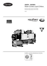
“FREE COOLING SYSTEM”<br />
Working mode<br />
“WINTER”<br />
(Chilled Water)<br />
“FREE COOLING SYSTEM”<br />
Working mode<br />
“SPRING - AUTUMN”<br />
(Direct Expansion + Chilled Water)<br />
“FREE COOLING SYSTEM”<br />
Working mode<br />
“SUMMER”<br />
(Direct Expansion)<br />
11
4. Two Sources<br />
system<br />
“Two Sources” for the maximum guarantee of continued operation or the<br />
use of excess energy from a centralized plant.<br />
This system (accessory) envisages the installation inside the machine of a<br />
second cooling source, complete with its own regulation and totally<br />
independent of the primary one. Only the aluminium fin pack is common to<br />
the two sources. It is double the size compared to the standard machine,<br />
thus enabling both to reach very high heat exchange efficiency levels.<br />
Two Sources<br />
Twin Safety Twin Safety Technology Technology<br />
The “Two Sources” system guarantees continuity of the cooling<br />
function if, for whatever reason, the primary source is not available:<br />
overload, maintenance, night-time/ seasonal stoppage or for any<br />
type of emergency.<br />
DX/TS: in this application the machine has a direct expansion<br />
cooling source, with one or two compressors, and another with<br />
chilled water. The primary source is normally the chilled water one<br />
connected to the refrigeration plant of the building or to the district<br />
cooling system, and the emergency one is the direct expansion<br />
connected in its turn to a remote <strong>air</strong>-cooled or a built-in watercooled<br />
condensers. Alternatively, the primary source can be direct<br />
expansion and the emergency one water - groundwater or<br />
acqueduct.<br />
CW/TS: both cooling sources are chilled water coils. The primary<br />
source is normally connected to the refrigeration plant of the<br />
building or to the district cooling system. The emergency source<br />
can be connected to a dedicated water chiller or to water -<br />
groundwater or acqueduct.<br />
12
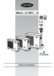
“TWO SOURCES SYSTEM”<br />
Working mode<br />
“Direct Expansion”<br />
“TWO SOURCES SYSTEM”<br />
Working mode<br />
“Chilled Water”<br />
“TWO SOURCES SYSTEM”<br />
Double water circuit version<br />
13 11
5. Series:<br />
CLOSE CONTROL AIR CONDITIONERS<br />
APPLICATIONS<br />
Designed and constructed for installation in areas with medium to high density of electronic<br />
equipment, the P Series - thanks to its wide range of accessories - also has interesting<br />
applications in industrial areas, power stations, recording studios, conference room and<br />
wherever rigorous <strong>control</strong> of environmental parameters is required.<br />
Main characteristics<br />
■<br />
■<br />
Direct expansion from 6 to 100 kW<br />
OPA: upward <strong>air</strong> discharge<br />
UPA: downward <strong>air</strong> discharge.<br />
Chilled water from 10 to 200 kW<br />
OPU: upward <strong>air</strong> discharge<br />
UPU: downward <strong>air</strong> discharge.<br />
14
5. Series:<br />
CLOSE CONTROL AIR CONDITIONERS<br />
Upflow <strong>air</strong> supply<br />
Down flow <strong>air</strong> supply<br />
16
OPA: direct expansion <strong>air</strong> <strong>conditioners</strong> with <strong>air</strong> cooled or water condensers<br />
and up-flow <strong>air</strong> supply<br />
Models 71a 111a 141a 211 251 301 302 372 361 461 422 512 491 612 662 852 932<br />
Performance<br />
Tot. cooling cap. kW: 6,9 11,3 14,9 21,5 26,1 31,1 31,3 38,3 37,6 48,2 44,6 52,6 52,8 64,2 69,2 88,0 96,6<br />
Sens cooling cap. kW: 6,7 10,9 12,3 20,6 22,4 29,1 28,9 31,9 36,8 44,3 43,4 46,2 51,7 59,5 61,7 70,1 86,0<br />
Airflow m 3 /h: 2.200 3.200 3.200 7.000 7.000 8.700 8.700 8.700 14.500 14.500 14.500 14.500 17.900 17.900 17.900 17.900 22.500<br />
EER 2,99 3,27 3,39 3,26 3,19 3,21 3,35 3,04 3,36 3,49 3,38 3,21 3,60 3,36 3,32 3,37 3,55<br />
SPL:dB(A) 49 49 49 56 56 58 58 58 63 63 63 63 68 68 68 68 69<br />
Dimensions & weight<br />
Lenght mm. 750 750 750 860 860 1.410 1.410 1.410 1.750 1.750 1.750 1.750 2.300 2.300 2.300 2.300 2.640<br />
Depth mm. 600 600 600 880 880 880 880 880 880 880 880 880 880 880 880 880 880<br />
Height mm. 1.990 1.990 1.990 1.990 1.990 1.965 1.990 1.990 1.990 1.990 1.990 1.990 1.990 1.990 1.990 1.990 1.990<br />
Net weight kg. 180 200 210 270 270 320 340 350 440 450 450 500 540 640 640 660 860<br />
UPA: direct expansion <strong>air</strong> <strong>conditioners</strong> with <strong>air</strong> cooled or water condensers<br />
and down-flow <strong>air</strong> supply<br />
Models 71a 111a 141a 211 251 301 302 372 361 461 422 512 491 612 662 852 932<br />
Performance<br />
Tot. cooling cap. kW: 6,9 11,3 14,9 21,5 26,1 31,1 31,3 38,3 37,6 48,2 44,6 52,6 52,8 64,2 69,2 88,0 96,6<br />
Sens cooling cap. kW: 6,7 10,9 12,3 20,6 22,4 29,1 28,9 31,9 36,8 44,3 43,4 46,2 51,7 59,5 61,7 70,1 86,0<br />
Airflow m 3 /h: 2.200 3.200 3.200 7.000 7.000 8.700 8.700 8.700 14.500 14.500 14.500 14.500 17.900 17.900 17.900 17.900 22.500<br />
EER 2,97 3,29 3,39 3,28 3,21 3,23 3,38 3,06 3,40 3,47 3,46 3,23 3,62 3,36 3,26 3,38 3,58<br />
SPL:dB(A) 49 49 49 56 56 58 58 58 63 63 63 63 68 68 68 68 69<br />
Dimensions & weight<br />
Lenght mm. 750 750 750 860 860 1.410 1.410 1.410 1.750 1.750 1.750 1.750 2.300 2.300 2.300 2.300 2.640<br />
Depth mm. 600 600 600 880 880 880 880 880 880 880 880 880 880 880 880 880 880<br />
Height mm. 1.990 1.990 1.990 1.990 1.990 1.965 1.990 1.990 1.990 1.990 1.990 1.990 1.990 1.990 1.990 1.990 1.990<br />
Net weight kg. 180 200 210 270 270 320 340 350 440 450 450 500 540 640 640 660 860<br />
OPU: with chilled water coil and up-flow <strong>air</strong> supply<br />
Models 10a 20a 30 50 80 110 160 220<br />
Performance<br />
Tot. cooling cap. kW: 10,5 19,3 31,0 39,2 69,6 87,7 145,4 178,6<br />
Sens cooling cap. kW: 8,8 15,6 27,8 33,9 60,1 73,0 117,4 148,7<br />
Airflow m 3 /h: 2.200 3.500 7.800 8.300 16.000 17.000 26.400 34.800<br />
EER 32,80 24,71 20,61 22,00 23,12 26,00 26,33 25,24<br />
SPL:dB(A) 47 49 56 56 59 61 64 65<br />
Dimensions & weight<br />
Lenght mm. 750 750 860 860 1.750 1.750 2.640 3.495<br />
Depth mm. 600 600 880 880 880 880 880 880<br />
Height mm. 1.990 1.990 1.990 1.990 1.990 1.990 1.990 1.990<br />
Net weight kg. 155 160 220 240 340 360 540 700<br />
UPU: with chilled water coil and down-flow <strong>air</strong> supply<br />
Models 10a 20a 30 50 80 110 160 220<br />
Performance<br />
Tot. cooling cap. kW: 10,5 19,3 31,0 39,2 69,6 87,7 145,4 178,6<br />
Sens cooling cap. kW: 8,8 15,6 27,8 33,9 60,1 73,0 117,4 148,7<br />
Airflow m 3 /h: 2.200 3.500 7.800 8.300 16.000 17.000 26.400 34.800<br />
EER 32,80 24,71 20,61 22,00 23,12 26,00 26,33 25,24<br />
SPL:dB(A) 47 49 56 56 59 61 64 65<br />
Dimensions & weight<br />
Lenght mm. 750 750 860 860 1.750 1.750 2.640 3.495<br />
Depth mm. 600 600 880 880 880 880 880 880<br />
Height mm. 1.990 1.990 1.990 1.990 1.990 1.990 1.990 1.990<br />
Net weight kg. 155 160 220 240 340 360 540 700<br />
Notes:<br />
The performance is referred to: refrigerant R410; condensing<br />
temperature: 45°C; inlet <strong>air</strong>: 24°C - 45% RH; for chilled water:<br />
7/12°C. The SPL is referred to 2 m distance, 1,5 m height, free<br />
field and sound damped discharge mouth. Available static<br />
pressure: 30 Pa. EER = Electro Efficiency Ratio = Total cooling<br />
capacity / compressors power input + fans power input. The<br />
above performances don’t consider the heat generated by<br />
the fans which must be added to the thermal load of the<br />
system.<br />
17
6. Series:<br />
AIR CONDITIONERS FOR LARGE DATA CENTERS:<br />
PERIMETRAL INSTALLATION<br />
APPLICATIONS<br />
Ever-greater importance is being placed on reducing electrical consumption in the design of <strong>air</strong> conditioning<br />
plant for large data centers.<br />
Servers are installed according to the layouts: “cold corridor” (app. 20-25°C) and “hot corridor” (up to<br />
30-35°C), with very low humidity - never over 30%. These thermo-hygrometric conditions ensure that the<br />
entire cooling capacity of the plant is sensible, render compatible the high temperatures of the water supplied<br />
to the cold water coils and optimize the function of chillers with free cooling systems.<br />
In addition, due to the necessities of cable housing and for the distribution of the enormous quantities of <strong>air</strong><br />
required to cool the servers, the height of the false floor has been constantly increased to now reach the<br />
current 600-800 millimetres. This creates an ample space below the <strong>air</strong> conditioner destined to the installation<br />
of the under-base. This large space under the raised floor was therefore considered as the housing for the<br />
discharge fans. The <strong>air</strong> <strong>conditioners</strong> are supplied in two separate sections: the under-base containing the<br />
discharge fans to be installed under the floating floor, and the treatment unit with the exchanger coil, filters<br />
and the electrical panel.<br />
Three great advantages have thus been obtained without increasing the footprint but only exploiting the<br />
space available:<br />
1. At equal footprint, we can dimension the exchanger coil using also the space inside the <strong>air</strong> conditioner left<br />
free by the fans. In this way it is possible to increase the frontal section of the coil by about 40-50%,<br />
reducing the <strong>air</strong> side pressure drop and therefore the energy consumption of the fans.<br />
2. Also the size of the <strong>air</strong> filters, installed upstream the cold coil, is increased in the same way, reducing the<br />
pressure drop and the frequency of the replacement of the same filters.<br />
3. The fans in the under-base expel the treated <strong>air</strong> horizontally and completely without obstacles, further<br />
increasing the energy efficiency of the machines.<br />
The under-base with fans is supplied with the height indicated on the order by the Customer. The two<br />
sections, shipped separately, are easy to install on-site, requiring only the electrical connection between the<br />
two junction boxes in the machine and in the under-base.<br />
Main characteristics<br />
■<br />
■<br />
Direct expansion from 60 to 180 kW<br />
UGA: downward <strong>air</strong> discharge.<br />
Chilled water from 140 to 300 kW<br />
UGU: downward <strong>air</strong> discharge.<br />
18
6. Series:<br />
AIR CONDITIONERS FOR LARGE DATA CENTERS:<br />
PERIMETRAL INSTALLATION<br />
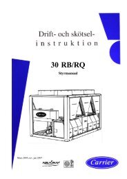
Standard execution for perimetral<br />
installation inside the data Center.<br />
The height of the raised floor must<br />
be of at least 600 mm.<br />
In data centers where the limited<br />
height of the raised floor does not<br />
permit this type of installation,<br />
it is still possible to use this<br />
Series of machines by installing<br />
the under-base with the fans<br />
above the floor.<br />
In this case the under-base is<br />
supplied in a standard height (600<br />
mm) and with lateral closure panels.<br />
It is therefor possible to exploit the<br />
advantages of this Series provided<br />
that the height of the ceiling allows<br />
for good suction of <strong>air</strong>.<br />
For installation outside of the data<br />
center.<br />
20
UGA: direct expansion <strong>air</strong> <strong>conditioners</strong> with <strong>air</strong> cooled or water condensers<br />
and down-flow <strong>air</strong> supply<br />
Models 461 612 932 1232 1342 1732<br />
Performance<br />
Tot. cooling cap. kW: 45,9 60,6 53,5 107,5 132,7 166,3<br />
Sens cooling cap. kW: 40,3 46,8 53,2 89,0 119,5 134,1<br />
Airflow m 3 /h: 12.000 12.000 24.000 24.000 36.000 36.000<br />
EER 3,47 3,10 3,61 2,73 3,34 3,32<br />
SPL:dB(A) 58 58 68 68 69 69<br />
Dimensions & weight<br />
Lenght mm. 1.470 1.470 2.370 2.370 3.270 3.270<br />
Depth mm. 921 921 921 921 921 921<br />
Height mm. 1.990 1.990 1.990 1.990 1.990 1.990<br />
Net weight kg. 630 680 870 940 1.160 1.250<br />
UGU: with chilled water coil and down-flow <strong>air</strong> supply<br />
Models 70 150 230 300<br />
Performance<br />
Tot. cooling cap. kW: 59,2 128,0 193,8 256,1<br />
Sens cooling cap. kW: 50,5 105,3 159,0 210,7<br />
Airflow m 3 /h: 12.000 24.000 36.000 44.000<br />
EER 29,33 30,98 31,21 30,35<br />
SPL:dB(A) 58 61 64 66<br />
Dimensions & weight<br />
Lenght mm. 1.320 2.220 3.120 4.020<br />
Depth mm. 921 921 921 921<br />
Height mm. 1.990 1.990 1.990 1.990<br />
Net weight kg. 610 750 930 1.250<br />
Notes:<br />
The performance is referred to: refrigerant R410; condensing temperature: 45°C; inlet <strong>air</strong>: 24°C - 45% RH; for chilled water: 7/12°C. The SPL is referred to 2<br />
m distance, 1,5 m height, free field and sound damped discharge mouth. Available static pressure: 30 Pa. EER = Electro Efficiency Ratio = Total cooling<br />
capacity / compressors power input + fans power input. The above performances don’t consider the heat generated by the fans which must be added to<br />
the thermal load of the system.<br />
21
7. Series:<br />
AIR CONDITIONERS FOR LARGE DATA CENTERS:<br />
IN-ROW INSTALLATION<br />
APPLICATIONS<br />
The design of <strong>air</strong> conditioning plant for large data centres increasingly requires the adoption of the concepts<br />
listed below. Indeed, they have now become consolidated international standard practice:<br />
■<br />
■<br />
■<br />
■<br />
■<br />
■<br />
The racks containing the servers are more often positioned according to the “hot corridor” and “cold<br />
corridor” layout.<br />
The working <strong>air</strong> temperatures are now allowed to go up to 30-35°C in the hot corridor and 20-25°C in the<br />
cold one. Consequently, also the water temperature rises up to 20-28°C. In this way the free cooling<br />
function is exploited at its best.<br />
Server capacities keep going up while their dimensions keep going down. This means that more servers<br />
can be installed in a rack so that some of these racks, remaining empty, can be removed. At the same time<br />
the heat dissipated rises and more capacity is required from the <strong>air</strong> <strong>conditioners</strong>.<br />
The servers work day and night albeit with a night time reduction of their capacity. It is therefore essential<br />
for the <strong>air</strong> conditioning installation to have an efficient modulating cooling capacity <strong>control</strong> and to be<br />
designed for the maximum energy saving and minimum environmental impact.<br />
In order to satisfy these requirements, a family of <strong>air</strong> <strong>conditioners</strong> has been designed and constructed to<br />
have the same dimensions as the racks, with rear suction from the hot corridor and frontal discharge into<br />
the cold one; with the following advantages:<br />
1. Use of the space freed up in the racks and therefore cold <strong>air</strong> is distributed as <strong>close</strong> as possible to the<br />
server i.e. where the heat is generated.<br />
2. Horizontal <strong>air</strong> suction and also horizontal <strong>air</strong> discharge: the <strong>air</strong> flow therefore does not change direction<br />
inside the machine, so avoiding the relative pressure drops and with an important consequent reduction<br />
of the power draw.<br />
Cooling, hydraulic and electrical connections from above or from below.<br />
Main characteristics<br />
■<br />
■<br />
Direct expansion from 20 to 40 kW<br />
HRA: horizontal <strong>air</strong> discharge<br />
Chilled water from 15 to 40 kW<br />
HRU: horizontal <strong>air</strong> discharge<br />
22
24<br />
7. Series:<br />
AIR CONDITIONERS FOR LARGE DATA CENTERS:<br />
IN-ROW INSTALLATION
HRA: direct expansion <strong>air</strong> <strong>conditioners</strong> for in-row installation<br />
Models 231 361<br />
Performance<br />
Tot. cooling cap. kW: 22,8 35,5<br />
Sens cooling cap. kW: 22,8 31,3<br />
Airflow m 3 /h: 7500 7500<br />
EER 3,41 3,41<br />
SPL:dB(A) 61 62<br />
Dimensions & weight<br />
Lenght mm. 600 600<br />
Depth mm. 1180 1180<br />
Height mm. 2000 2000<br />
Net weight kg. 215 215<br />
HRU: <strong>air</strong> <strong>conditioners</strong> with chilled water coil for in-row installation<br />
Models 40<br />
Performance<br />
Tot. cooling cap. kW: 42,5<br />
Sens cooling cap. kW: 39,4<br />
Airflow m 3 /h: 10000<br />
EER 21,30<br />
SPL:dB(A) 67<br />
Dimensions & weight<br />
Lenght mm. 600<br />
Depth mm. 1180<br />
Height mm. 2000<br />
Net weight kg. 190<br />
Notes:<br />
The performances are referred to: refrigerant R410; condensing temperature: 45°C; inlet <strong>air</strong>: 24°C - 45% RH; for chilled water: 7/12°C.<br />
The SPL is referred to 2 m distance, 1,5 m height, free field and sound damped discharge mouth.<br />
Available static pressure: 30 Pa. EER = Electro Efficiency Ratio = Total cooling capacity / compressors power input + fans power input.<br />
The above performances don’t consider the heat generated by the fans which must be added to the thermal load of the system.<br />
25
8. Series:<br />
AXIAL FAN AIR<br />
COOLED CONDENSERS<br />
Main characteristics<br />
■<br />
■<br />
■<br />
ACC/H: horizontal installation and vertical <strong>air</strong> discharge<br />
ACC/V: vertical installation and horizontal <strong>air</strong> discharge<br />
ACC/LT: for very low temperature; vertical installation and horizontal <strong>air</strong> discharge<br />
26
Air cooled condensers to be matched with Tecn<strong>air</strong> LV <strong>air</strong> <strong>conditioners</strong><br />
Models ACC 8 11 16 19 21 25 29<br />
Performance<br />
Nominal capacity (1) kW 8,3 10,8 16,5 19,9 21,5 24,8 29,8<br />
Air quantity m3/h 2.600 2.200 5.200 4.800 4.400 7.800 7.200<br />
Fans number n. 1 1 2 2 2 3 3<br />
Fans diameter mm 350 350 350 350 350 350 350<br />
Motor power input W 180 180 360 360 360 540 540<br />
Absorbed current Amps 0,85 0,85 1,7 1,7 1,7 1,7 2,5<br />
Sound pressure level (2) dB(A) 40 40 43 43 43 45 45<br />
Internal circuit volume dm3 2,0 3,0 3,0 4,0 5,0 4,0 6,0<br />
Dimensions & weight<br />
Lenght (H - V installation) mm 743 743 1.298 1.298 1.298 1.853 1.853<br />
Depth (H installation) mm 610 610 610 610 610 610 610<br />
Depth (V installation) mm 510 510 510 510 510 510 510<br />
Height (H installation ) mm 906 906 906 906 906 906 906<br />
Height (V installation ) mm 578 578 578 578 578 578 578<br />
Weight kg 20 29 29 33 37 42 48<br />
Models ACC 32 42 50 55 61 74 83<br />
Performance<br />
Nominal capacity (1) kW 32,3 43,1 50,3 56,1 62,0 75,4 84,0<br />
Air quantity m3/h 6.600 8.800 13.600 12.700 14.900 20.400 19.000<br />
Fans number n. 3 4 2 2 2 3 3<br />
Fans diameter mm 350 350 500 500 500 500 500<br />
Motor power input W 540 720 1.250 1.250 1.160 1.880 1.880<br />
Absorbed current Amps 2,5 3,4 5,5 5,5 5,5 8,3 8,3<br />
Sound pressure level (2) dB(A) 45 46 50 50 51 51 51<br />
Internal circuit volume dm3 6,0 10,0 9,0 12,0 14,0 13,0 17,0<br />
Dimensions & weight<br />
Lenght (H - V installation) mm 1.853 2.408 1.895 1.895 2.393 2.705 2.705<br />
Depth (H installation) mm 610 610 905 905 1.110 905 905<br />
Depth (V installation) mm 510 510 470 470 705 470 470<br />
Height (H installation ) mm 906 906 1.070 1.070 1.230 1.070 1.070<br />
Height (V installation ) mm 578 578 830 830 1.040 830 830<br />
Weight kg 54 71 94 102 177 132 144<br />
Notes:<br />
(1) Nominal capacity at 35°C ambient and 50°C condensing temperature; R410A<br />
(2) Sound pressure level in free field at 10 meters from the unit.<br />
Available accessories:<br />
ALUPAINT: for better protection of the aluminium fins (suggested in salt atmospheres);<br />
EC FANS: for energy saving.<br />
27
Our solution for<br />
Data Center<br />
P Series:<br />
Air <strong>conditioners</strong> <strong>close</strong> <strong>control</strong>:<br />
perimetric installation<br />
G Series:<br />
Air <strong>conditioners</strong> for large data centres:<br />
perimetric installation<br />
R Series:<br />
Air <strong>conditioners</strong> for large data centers:<br />
in-row installation<br />
28
TECNAIR LV<br />
CLOSE CONTROL AIR CONDITIONERS<br />
CLOSE CONTROL<br />
<strong>air</strong> <strong>conditioners</strong>
TECNAIR LV<br />
CLOSE CONTROL AIR CONDITIONERS<br />
TECNAIR LV S.p.A.<br />
21040 Uboldo - Varese - Italy<br />
Via Caduti della Liberazione, 53<br />
Phone + 39 02.96.99.11.1<br />
Fax. + 39 02.96.78.15.70<br />
E-mail: sales@tecn<strong>air</strong>lv.it<br />
www.tecn<strong>air</strong>lv.it<br />
76030207.1210