VL1000 ERS Luminaire User's Manual - Vari-Lite
VL1000 ERS Luminaire User's Manual - Vari-Lite
VL1000 ERS Luminaire User's Manual - Vari-Lite

You also want an ePaper? Increase the reach of your titles
YUMPU automatically turns print PDFs into web optimized ePapers that Google loves.
VARI❋LITE ® is a trademark owned by Genlyte Thomas Group LLC and is registered in the United States and other countries.<br />
<strong>VL1000</strong>, VL2000, VL2201, VL2202, VL2400 (and the individual product designations), VL3000, Series 1000 , Series 2000 ,<br />
Series 3000 , DICHRO❋TUNE , VARI❋IMAGE , and the <strong>Vari</strong>-<strong>Lite</strong> Asterisk are also trademarks owned by Genlyte Thomas Group LLC.<br />
VARI❋LITE® products are protected by one or more of the following patents, and other pending patent applications worldwide:<br />
U. S. Patents No. 6,123,436; 6,113,252; 6,046,861; 6,031,749; 6,011,640; 5,969,868; 5,959,768; 5,934,794; 5,882,107; 5,829,868; 5,825,548; 5,798,619;<br />
5,774,273; 5,769,527; 5,758,956; 5,728,994; 5,640,061; 5,590,954; 5,454,477; 5,432,691; 5,367,444; 5,329,431; 5,307,295; 5,282,121; 5,278,742; 5,209,560;<br />
5,186,536; 5,073,847; 5,010,459; 4,980,806; 4,972,306; 4,800,474; 4,779,176; 4,701,833; 4,602,321;<br />
U. S. Design Patents No. 439,356; 420,332; 417,300; 415,301; 413,995; 377,338; 366,712; 359,574; 350,408; 347,113;<br />
Australia Patents No. 693,691; 683,695; 667,109; 649,264; 646,588; 586,095; 576,400; 546,433;<br />
Australia Design Patents No. 128,796; 128,795;<br />
Canada Patents No. 2,070,670; 2,050,375; 1,270,675; 1,259,058; 1,181,795;<br />
Canada Design Patents No. 81,234; 81,233; 76,046;<br />
European (UK) Patents No. 0 652 400; 0 586 049; 0 565 218; 0 547 732; 0 534 710; 0 495 305; 0 474 202; 0 379 970; 0 253 082; 0 253 081; 0 248 974; 0 192<br />
882; 0 140 994; 0 060 068;<br />
Germany Patents No. 694 25 943.8; 693 14 122.0; 692 08 615.3; 692 07 692.1; 691 31 478.0; 691 21 029.2; 690 33 385.4; 37 89 166.9; 37 68 727.1; 37 51<br />
804.6; 37 50 201.8; 35 87 270.5; 32 79 888.1; 32 74 291.6;<br />
Germany Design Patents No. M 98 01 745.4; M 96 04 515.9; M 96 04 514.0; M 94 07 689.8; M 94 02 951.2; M 499 03 583.6; M 498 11 203.9; G 93 12 884.3;<br />
Spain Patents No. 2 090 191; 2 084 289; 2 020 960; 0 548 328;<br />
Spain Utility Model Patent No. 2.031.748;<br />
Spain Design Patents No. 0.137.502; 0.137.501; 0.133.573;<br />
Greece Patent No. 910.400.544;<br />
Hong Kong Patents No. 965/1990; 285/1987;<br />
Japan Patents No. 2,843,696; 2,059,669; 2,055,324; 2,002,168; 1,966,525; 1,889,481; 1,792,721; 1,770,241; 1,723,825; 1,683,007; 1,533,011;<br />
Japan Design Patents No. 985,985-1; 985,985; 947,552; 945,436-1; 945,436; 1,106,089; 1,077,598; 1,072,598; 1,060,414; 1,002,123;<br />
Korea Patents No. 76,310; 42,639; 283,770; 181,180;<br />
Korea Design Patents No. 209,896; 209,895;<br />
Mexico Patent No. 180,148;<br />
Singapore Patents No. 663/90; 134/87;<br />
Taiwan Patents No. 78,726; 66,975; 65,380; 28,275;<br />
United Kingdom Design Registrations No. 2082526; 2072562; 2056387; 2056386; 2042174; 2038212; 2033108; 2029499.<br />
Neutrik®, PowerCon®, and EtherCon® are registered trademarks of Neutrik, Inc.<br />
All other brand or product names which may be mentioned in this manual are trademarks or registered trademarks of their respective companies or<br />
organizations.<br />
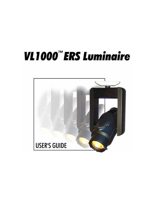
<strong>VL1000</strong> <strong>ERS</strong> <strong>Luminaire</strong> User’s <strong>Manual</strong><br />
The information furnished in this manual is for informational use only and is subject to change without notice. Please check www.vari-lite.com for latest<br />
version. <strong>Vari</strong>-<strong>Lite</strong> assumes no responsibility or liability for any errors or inaccuracies that may appear in this manual. All information and graphics are<br />
property of Genlyte Thomas Group LLC, 10911 Petal St. Dallas, TX 75238.<br />
Version as of: 04-Apr-03<br />
Part number: 02.9663.0001 D<br />
<strong>VL1000</strong> <strong>ERS</strong> <strong>Luminaire</strong> User’s <strong>Manual</strong><br />
©2002-2003 Genlyte Thomas Group LLC. All Rights Reserved.
FOREWORD<br />
How To Obtain Warranty Service<br />
A copy of the <strong>Vari</strong>-<strong>Lite</strong> Limited Warranty was included in the shipping package for this<br />
VARI❋LITE® product.<br />
To obtain warranty service, please contact customer service at 1-877-VARI-LITE (1-877-827-4548) or<br />
customerservice@vari-lite.com and request a Return Material Authorization (RMA) for warranty<br />
service. You will need to provide the model and serial number of the item being returned, a<br />
description of the problem or failure and the name of the registered user or organization. If available,<br />
you should have your sales invoice to establish the date of sale as the beginning of the warranty period.<br />
Once you obtain the RMA, pack the unit in a secure shipping container or in its original packing box.<br />
Fill out the RMA form included at the end of this manual and place in shipping container along with a<br />
copy of your invoice (if available). Write the RMA number legibly on or near the shipping address<br />
label and return the unit, freight prepaid to:<br />
<strong>Vari</strong>-<strong>Lite</strong><br />
10911 Petal St.<br />
Dallas, TX 75238<br />
Attention: Warranty Service<br />
As stated in the warranty, it is required that the shipment be insured and FOB our service center.<br />
02.9663.0001 D 04-Apr-03 i
VARI❋LITE® - <strong>VL1000</strong> <strong>ERS</strong> LUMINAIRE USER’S MANUAL<br />
Compliance Notice<br />
FCC<br />
This equipment has been tested and found to comply with the limits for a Class A digital device<br />
pursuant to Part 15 of FCC Rules. These limits are designed to provide reasonable protection against<br />
harmful interference when this equipment is operated in a commercial environment. This equipment<br />
generates, uses, and can radiate radio frequency energy and, if not installed and used in accordance<br />
with <strong>Vari</strong>-<strong>Lite</strong> system, service, and safety guidelines, may cause harmful interference to radio<br />
communications. Operation of this equipment in a residential area is likely to cause harmful<br />
interference, in which case the user will be required to correct the interference at his/her own expense.<br />
Declaration of Conformity<br />
We declare, under our sole responsibility, that this product complies with the relevant clauses of the<br />
following standards and harmonized documents:<br />
Safety<br />
EN 60598-1:1997 <strong>Luminaire</strong> Safety Standard, General Requirements<br />
EN 60598-2 17:1989 Specification for <strong>Luminaire</strong>s for Stage and Studio Lighting<br />
EMC<br />
EN 55022A:1994 Radiated and Conducted Emissions<br />
EN 50082-1:1997 Generic Immunity Standard<br />
We certify that the product conforms to the protection requirements of council directives: 73/23/EEC<br />
(LVD) and 89/336/EEC (EMC)<br />
ii 04-Apr-03 02.9663.0001 D
FOREWORD<br />
Safety Notice<br />
It is extremely important to read ALL safety information and instructions provided in this manual and<br />
any accompanying documentation before installing and operating the products described herein. Heed<br />
all cautions and warnings during installation and use of this product.<br />
Safety symbols used throughout this manual are as follows:<br />
CAUTION advising of potential damage to product.<br />
WARNING advising of potential injury or death to persons.<br />
GENERAL INFORMATION PERTAINING TO PROTECTION AGAINST ELECTRICAL SHOCK,<br />
FIRE, EXPOSURE TO EXCESSIVE UV RADIATION, AND INJURY TO P<strong>ERS</strong>ONS CAN BE<br />
FOUND BELOW.<br />
WARNING:<br />
INSTRUCTIONS FOR CONTINUED PROTECTION AGAINST FIRE<br />
1. VARI❋LITE® luminaires have been designed for use with specific lamp types. The <strong>VL1000</strong><br />
<strong>ERS</strong> luminaire requires a specific type of Oshio or Philips lamp. Installing another type of lamp<br />
may be hazardous.<br />
2. <strong>Luminaire</strong>s may be mounted on any type of surface as long as mounting instructions are followed.<br />
See instructions detailed in this manual.<br />
3. Note distance requirement from combustible materials or illuminated objects for VARI❋LITE®<br />
luminaires.<br />
WARNING:<br />
INSTRUCTIONS FOR CONTINUED PROTECTION AGAINST ELECTRICAL SHOCK<br />
1. VARI❋LITE® luminaires are designed for dry locations only. Exposure to rain or moisture may<br />
damage luminaire.<br />
2. Disconnect power before servicing any VARI❋LITE® equipment.<br />
3. Servicing to be performed by qualified personnel only.<br />
02.9663.0001 D 04-Apr-03 iii
VARI❋LITE® - <strong>VL1000</strong> <strong>ERS</strong> LUMINAIRE USER’S MANUAL<br />
WARNING:<br />
INSTRUCTIONS FOR CONTINUED PROTECTION AGAINST EXCESSIVE EXPOSURE<br />
TO UV RADIATION<br />
1. Many VARI❋LITE® luminaires use a lamp that produces UV radiation. DO NOT look directly at<br />
lamp.<br />
2. It is hazardous to operate luminaires without lens or shield. Shields, lenses, or ultraviolet screens<br />
shall be changed if they have become visibly damaged to such an extent that their effectiveness is<br />
impaired. For example, by cracks or deep scratches.<br />
WARNING:<br />
INSTRUCTIONS FOR PROTECTION AGAINST INJURY TO P<strong>ERS</strong>ONS<br />
1. Exterior surfaces of the luminaire will be hot during operation. Use appropriate safety equipment<br />
(gloves, eye protection, etc.) when handling and adjusting hot equipment and components.<br />
2. <strong>Luminaire</strong>s will have a hot lamp when operating. Disconnect power and allow lamp to cool before<br />
replacing.<br />
3. Arc lamps emit ultraviolet radiation which can cause serious skin burn and eye inflammation.<br />
Additionally, arc lamps operate under high pressure at very high temperatures. Should the lamp<br />
break, there can exist a danger of personal injury and/or fire from broken lamp particles being<br />
discharged.<br />
4. Wear eye protection when relamping.<br />
5. Appropriate safety equipment (gloves, eye protection) should be used when handling damaged<br />
lamps.<br />
6. If lamp is touched with bare hands, clean lamp with denatured alcohol and wipe with lint-free<br />
cloth before installing or powering up the luminaire.<br />
7. The lamp shall be changed if it has become damaged or thermally deformed.<br />
WARNING:<br />
RF INTERFERENCE<br />
1. This is a Class A product. In a domestic environment this product may cause radio interference, in<br />
which case, the user may be required to take adequate measures.<br />
ARC LAMP CHARACTERISTIC CONSIDERATIONS<br />
1. Arc lamps require a period of time to relight after a power interruption or a severe voltage dip. In<br />
some cases, lamp will automatically relight after it has cooled depending on Lamp Power-Up State<br />
configuration setting.<br />
2. Burning position is Universal.<br />
iv 04-Apr-03 02.9663.0001 D
FOREWORD<br />
Sicherheitshinweise<br />
Es ist äußerst wichtig, ALLE Sicherheitsinformationen und -hinweise in diesem Handbuch und dem<br />
beiliegenden Informationsmaterial zu lesen, bevor Sie die hierin beschriebenen Produkte installieren<br />
bzw. bedienen. Halten Sie bei der Installation und dem Einsatz dieses Produkts alle Warnhinweise und<br />
Vorsichtsmaßnahmen ein.<br />
Folgende Sicherheitssymbole werden in diesem Handbuch verwendet:<br />
VORSICHT - weist auf möglichen Produktschaden hin.<br />
WARNUNG - weist auf mögliche Körperverletzung und Lebensbedrohung hin.<br />
NACHSTEHEND FINDEN SIE ALLGEMEINE HINWEISE ÜBER<br />
SICHERHEITSVORKEHRUNGEN GEGEN ELEKTROSCHOCK, FEUER, ÜBERHÖHTE UV-<br />
STRAHLUNG UND KÖRPERVERLETZUNGEN.<br />
WARNUNG:<br />
HINWEISE ZUM FEU<strong>ERS</strong>CHUTZ<br />
1. VARI❋LITE®-Scheinwerfer sind ausschließlich für den Einsatz mit bestimmten Lampentyps.<br />
Achten Sie auf den Lampentyp (specific type of Oshio or Philips lamp), bevor Sie die jeweiligen<br />
Lampen ersetzen. Die Installation eines anderen Lampentyps kann gefährlich sein.<br />
2. Scheinwerfer können auf jeder beliebigen Oberfläche montiert werden, solange Sie die<br />
Montageanweisungen befolgen. Detaillierte Hinweise finden Sie in diesem Handbuch.<br />
3. Beachten Sie die Einhaltung des erforderlichen Sicherheitsabstandes der VARI❋LITE®-<br />
Scheinwerfer von brennbarem Material oder beleuchteten Objekten.<br />
WARNUNG:<br />
HINWEISE ZUM SCHUTZ GEGEN ELEKTROSCHOCK<br />
1. VARI❋LITE®-Scheinwerfer eignen sich ausschließlich für trockene Standorte. Regen oder<br />
Feuchtigkeit können die Scheinwerfer beschädigen.<br />
2. Unterbrechen Sie die Stromzufuhr, bevor Sie mit der Arbeit an VARI❋LITE®-Geräten beginnen.<br />
3. Die Geräte sollten nur von qualifiziertem Personal gewartet werden.<br />
02.9663.0001 D 04-Apr-03 v
VARI❋LITE® - <strong>VL1000</strong> <strong>ERS</strong> LUMINAIRE USER’S MANUAL<br />
WARNUNG:<br />
HINWEISE ZUM SCHUTZ GEGEN ÜBERHÖHTE UV-STRAHLUNG<br />
1. Viele VARI❋LITE®-Scheinwerfer verwenden die Lampentyp, der UV-Strahlen abgibt.<br />
SCHAUEN SIE NICHT direkt in die Lampe.<br />
2. Es ist gefährlich, Leuchten ohne Linsen oder Blenden zu bedienen. Blenden, Linsen oder<br />
Ultraviolettschirme müssen ausgetauscht werden, sofern deren Schutzwirkung durch sichtbare<br />
Beschädigung (z. B. Sprünge oder Schrammen) eingeschränkt ist.<br />
WARNUNG:<br />
HINWEISE ZUM SCHUTZ GEGEN KÖRPERVERLETZUNGEN<br />
1. Bei Betrieb sind die Außenflächen der Scheinwerfer heiß. Verwenden Sie bei der Bedienung von<br />
aufgeheizter Apparatur die jeweils geeignete Sicherheitsausrüstung (Handschuhe, Augenschutz<br />
etc.).<br />
2. Bei Betrieb der Scheinwerfer ist die Lampe heiß. Unterbrechen Sie die Stromzufuhr und lassen Sie<br />
die Lampe abkühlen, wenn Sie diese austauschen.<br />
3. Bogenlampen senden ultraviolette Strahlen aus, die Hautverbrennungen und Augenentzündungen<br />
verursachen können. Der Betrieb von Bogenlampen erfolgt unter Hochdruck und bei hohen<br />
Temperaturen. Sollte die Lampe zerbrechen, besteht die Gefahr von Körperverletzung bzw. von<br />
Feuer, das von Lampenteilen ausgelöst werden kann.<br />
4. Tragen Sie beim Austausch der Lampen einen Augenschutz.<br />
5. Die geeignete Sicherheitsausrüstung (Handschuhe, Augenschutz) sollte beim Umgang mit<br />
beschädigten Lampen verwendet werden.<br />
6. Wenn die Lampe mit bloßen Händen berührt wird, reinigen Sie sie mit denaturiertem Alkohol und<br />
einem flusenfreien Tuch, bevor Sie die Scheinwerfer installieren oder in Betrieb nehmen.<br />
7. Wenn die Lampe beschädigt oder durch Hitzeeinwirkung deformiert ist, muß diese ausgetauscht<br />
werden.<br />
WARNUNG:<br />
HF-INTERFERENZ<br />
1. Es handelt sich um ein Produkt der Klasse A. In einer Wohnumgebung kann das Produkt Hochfrequenzstörungen<br />
verursachen. In diesem Fall müssen eventuell geeignete Maßnahmen getroffen<br />
werden.<br />
BESONDERHEITEN VON BOGENLAMPEN<br />
1. Bogenlampen benötigen eine gewisse Zeitdauer, um nach einem Stromausfall oder einem<br />
Spannungsgefälle wieder aufzuleuchten. In einigen Fällen wird die Lampe nach Abkühlung<br />
automatisch wieder aufleuchten, je nach der Systemkonfigurationseinstellung des Lampeneinschaltungsstatus.<br />
2. Die Brennposition ist Universal.<br />
vi 04-Apr-03 02.9663.0001 D
FOREWORD<br />
Notes de sécurité<br />
Avant de procéder à l’installation des produits décrits dans ce guide et de les mettre en marche, il est<br />
extrêmement important de lire TOUS les renseignements et TOUTES les directives de sécurité<br />
contenues dans ce guide ainsi que toute documentation jointe. Tenir compte de tous les avertissements<br />
et suivre toutes les précautions pendant l’installation et l’utilisation de cet appareil.<br />
Les symboles de sécurité utilisés dans ce guide sont les suivants :<br />
ATTENTION Ce symbole annonce que l’appareil risque d’être endommagé.<br />
AVERTISSEMENT Ce symbole annonce qu’il y a risque d’accident grave ou même fatal.<br />
CETTE SECTION CONTIENT DES INFORMATIONS GÉNÉRALES POUR SE PROTÉGER<br />
CONTRE LES DÉCHARGES ÉLECTRIQUES , LES INCENDIES, L’EXPOSITION EXCESSIVE<br />
AUX RAYONS UV ET TOUT AUTRE ACCIDENT POUVANT ENTRAÎNER DES BLESSURES.<br />
AVERTISSEMENT:<br />
DIRECTIVES POUR SE PROTÉGER CONTRE LES INCENDIES<br />
1. Les luminaires VARI❋LITE® ont été conçus pour être utilisés uniquement avec certaines type de<br />
lampes. Vérifier le type de lampe (specific type of Oshio or Philips lamp) avant de remplacer les<br />
lampes. L’installation d’un autre type de lampe peut poser un danger.<br />
2. Les luminaires peuvent être fixés sur tout type de surface tant que les directives de montage sont<br />
respectées. Voir les explications détaillées dans ce guide.<br />
3. Vérifier la distance à respecter entre les matériaux combustibles ou les objets illuminés et les<br />
luminaires VARI❋LITE®.<br />
AVERTISSEMENT:<br />
DIRECTIVES POUR SE PROTÉGER CONTRE LES DÉCHARGES ÉLECTRIQUES<br />
1. Les luminaires VARI❋LITE® sont conçus pour une utilisation au sec uniquement. Une<br />
exposition à la pluie et à l’humidité risque d’endommager le luminaire.<br />
2. Débrancher l’appareil avant de procéder à la révision de tout matériel VARI❋LITE®.<br />
3. Les révisions doivent être effectuées uniquement par des personnes qualifiées.<br />
02.9663.0001 D 04-Apr-03 vii
VARI❋LITE® - <strong>VL1000</strong> <strong>ERS</strong> LUMINAIRE USER’S MANUAL<br />
AVERTISSEMENT:<br />
DIRECTIVES POUR SE PROTÉGER CONTRE UNE EXPOSITION EXCESSIVE AUX<br />
RAYONS UV<br />
1. Plusieurs luminaires VARI❋LITE® utilisent une lampe qui produit des rayons UV. NE PAS fixer<br />
son regard sur la lampe.<br />
2. L’utilisation des luminaires sans lentille ou blindage pose des risques. Tous blindages, lentilles ou<br />
écrans ultraviolet visiblement endommagés au point que leur efficacité en est affectée doivent être<br />
remplacés, par exemple s’il y a des fissures ou de profondes rayures.<br />
AVERTISSEMENT:<br />
DIRECTIVES POUR SE PROTÉGER CONTRE LES ACCIDENTS POUVANT ENTRAÎNER<br />
DES BLESSURES<br />
1. Les surfaces externes du luminaire deviennent brûlantes quand l’appareil est en marche. Pour<br />
manœuvrer ou ajuster des appareils brûlants et leurs composants, se protéger suffisamment (gants,<br />
protection pour les yeux, etc.).<br />
2. La lampe du luminaire est brûlante lorqu’il est en marche. Débrancher le courant et attendre que la<br />
lampe ait refroidi avant de la remplacer.<br />
3. Les lampes à arc émettent des rayons ultraviolets pouvant causer de graves brûlures sur la peau et<br />
une inflammation des yeux. De plus, les lampes à arc fonctionnent sous haute tension à de très<br />
hautes températures. Si la lampe se casse, les particules de la lampe cassée peuvent causer<br />
blessures et/ou incendie en s’éparpillant.<br />
4. Se protéger les yeux pour remplacer la lampe.<br />
5. Utiliser des appareils de protection appropriés (gants, protection des yeux) pour manier des lampes<br />
endommagées.<br />
6. Si la lampe a été touchée avec des mains nues, la nettoyer avec de l’alcool dénaturé et l’essuyer<br />
avec un chiffon non-pelucheux avant d’installer ou de brancher le luminaire.<br />
7. Si la lampe a été endommagée ou a reçu une déformation thermique, elle doit être remplacée.<br />
AVERTISSEMENT:<br />
INTERFÉRENCE RF<br />
1. Cet appareil est de Classe A. Dans un environnement domestique, cet appareil peut causer des<br />
interférences radio, et si c’est le cas, l’utilisateur peut avoir à prendre des mesures adéquates.<br />
CONSIDÉRATIONS DES CARACTÉRISTIQUES DE LAMPES À ARC<br />
1. Après une interruption de courant ou une baisse importante de voltage, les lampes à arc mettent du<br />
temps avant de se rallumer. Dans certains cas, la lampe se rallumera automatiquemet après s’être<br />
refroidie. Cela dépend de la manière dont le système est réglé pour le statut de mise en marche de<br />
la lampe.<br />
2. La position Brûler est Universelle.<br />
viii 04-Apr-03 02.9663.0001 D
FOREWORD<br />
Aviso sobre Seguridad<br />
Es muy importante leer TODA la información e instrucciones sobre seguridad que se indica en este<br />
manual así como en los documentos adjuntos antes de instalar y operar los productos descritos. Se<br />
debe prestar atención a todos los avisos y advertencias durante la instalación y uso de este producto.<br />
Los símbolos de seguridad usados en este manual son los siguientes:<br />
CUIDADO, indica posibles daños al producto.<br />
ADVERTENCIA, indica posibles lesiones o muerte a las personas.<br />
LA INFORMACIÓN GENERAL RELACIONADA A LA PROTECCIÓN CONTRAGOLPES DE<br />
CORRIENTE ELÉCTRICA, INCENDIO, EXPOSICIÓN EXCESIVA A RADIACIÓN ULTRA<br />
VIOLETA Y LESIONES A LAS P<strong>ERS</strong>ONAS SE PUEDE ENCONTRAR SEGUIDAMENTE:<br />
ADVERTENCIA:<br />
INSTRUCCIONES PARA PROTECCIÓN CONTINUA CONTRA INCENDIO<br />
1. Las luminarias VARI❋LITE® han sido diseñadas para ser usadas solamente con algunas<br />
lámparas. Tome nota del tipo de lámpara (specific type of Oshio or Philips lamp) antes de<br />
reemplazarla. Instalación de otro tipo de lámpara puede ser peligroso.<br />
2. Las luminarias se pueden instalar en cualquier tipo de superficie siempre que se sigan las<br />
instrucciones de instalación. Vea las instrucciones detalladas en este manual.<br />
3. Tome nota de los requerimientos de distancia de materiales combustibles u objetos iluminados<br />
para las luminarias VARI❋LITE®.<br />
ADVERTENCIA:<br />
INSTRUCCIONES PARA PROTECCIÓN CONTINUA CONTRA CHOQUE ELÉCTRICO<br />
1. Las luminarias VARI❋LITE® están diseñadas solamente para lugares secos. La exposición a la<br />
lluvia o humedad pueden dañar la luminaria.<br />
2. Desconecte la energía antes de dar servicio a cualquier equipo de VARI❋LITE®.<br />
3. El servicio debe ser realizado solamente por personal calificado.<br />
02.9663.0001 D 04-Apr-03 ix
VARI❋LITE® - <strong>VL1000</strong> <strong>ERS</strong> LUMINAIRE USER’S MANUAL<br />
ADVERTENCIA:<br />
INSTRUCCIONES PARA PROTECCIÓN CONTINUA CONTRA LA EXPOSICIÓN<br />
EXCESIVA DE RADIACIÓN ULTRA VIOLETA<br />
1. Muchas luminarias VARI❋LITE® usan un tipo de lámpara que produce radiación UV. NO mire<br />
directamente a la lámpara.<br />
2. Es peligroso operar luminarias sin lentes o protectores. Debe cambiar los protectores, lentes o<br />
pantallas ultravioletas si se aprecia que han sido dañadas, y que su efectividad pudiera estar<br />
deteriorada. Por ejemplo, si tuvieran rajaduras o raspaduras profundas.<br />
ADVERTENCIA:<br />
INSTRUCCIONES PARA PROTECCIÓN CONTRA LESIONES DE P<strong>ERS</strong>ONAS<br />
1. Las superficies exteriores de las luminarias están calientes durante su operación. Use un equipo de<br />
seguridad apropiado (guantes, protección para los ojos, etc.) cuando haga ajustes en el equipo y<br />
componentes que están calientes.<br />
2. Cuando las luminarias están en operación la lámpara estará muy caliente. Desconecte la energía y<br />
deje que la lámpara se enfríe antes de reemplazarla.<br />
3. Las lámparas de arco emiten radiaciones ultravioletas que pueden ocasionar serias quemaduras a la<br />
piel e inflamación a los ojos. Además, las lámparas de arco operan a alta presión y muy alta<br />
temperatura. Si la lámpara se rompe, puede existir el peligro de lesiones al personal o un incendio<br />
ocasionado por las partículas de la lámpara rota que se caen.<br />
4. Use protección para los ojos cuando vuelve a colocar una lámpara nueva.<br />
5. Use un equipo de seguridad apropiado (guantes, protección para los ojos, etc.) cuando trabaje con<br />
lámparas dañadas.<br />
6. Si toca la lámpara con las manos, limpie la lámpara con alcohol desnaturalizado y con tela sin<br />
pelusas antes de instalar o volver a conectar la luminaria.<br />
7. Cambie la lámpara si está dañada o deformada termicamente.<br />
ADVERTENCIA:<br />
INTERFERENCIA RF<br />
1. Este es un producto de Clase A. En el ambiente de la casa este producto puede ocasionar<br />
radiointerferencia, en cuyo caso, el usuario debe tomar las medidas adecuadas.<br />
CONSIDERACIONES SOBRE LAS CARACTERÍSTICAS DE LA LÁMPARA DE ARCO<br />
1. Las lámparas de arco requieren un período de tiempo para volver a iluminarse después de una<br />
interrupción de energía o de una severa caída de voltaje. En algunos casos, la lámpara se volverá a<br />
iluminar en forma automática después que se ha enfriado dependiendo de la configuración del<br />
sistema de energía de la lámpara.<br />
2. La posición de encendido es universal.<br />
x 04-Apr-03 02.9663.0001 D
FOREWORD<br />
_KHæPÔHçPÄ<br />
ÎÎæ%¿Ðá¿~ ÒÁ 'ê”ùÕÄQ>X^Åîƒ<br />
ûéQ>X^é_KHæPÔ±Žã‘ÿÔôáÅ’úÊÛп•ù<br />
Ú”sÙæÄ~ ƒÌÚöªÔÙæê”ÔôáéHçPÄÅ<br />
îTæÐçÒáÞ:ÒáÊÛп•<br />
ÄQ>X^âê” é_KQo"öªÒá¿ùÔ•<br />
õ”+4”UV |¿æ»ÔŠ2é:´”ÅîqŠP ËÚüé<br />
ûx›å±Žæß¿áê” é‘ÿÅ’úÊÛп•<br />
T :<br />
+4é’¢ ËÚüéEf;<br />
1. VARI❋LITE® –ÿzUê”\fJöªÔÁæ<br />
3Ðá¿ùÔ•\fJdµÔÙê”\fJé³<br />
( åäÕÕzÔÁæÒáÊÛп• é³é\fJ<br />
<br />
<br />
ƒÌã¾âÔ•<br />
–ÿzUê”ÄQ>X^é0æåÞá2ÞÔÆÉ”äéÁå2<br />
Jé+YæâýƒÌÎãÇâÈùÔ•f¦æß¿áê”ÄQ>X^<br />
ó–ÒáÊÛп•<br />
EXo-dµÔ 'ê”+ÓEXo-Ô+Ó³”+Ó"\,Õöª<br />
ÒáÊÛп•<br />
4. VARI❋LITE® –ÿzUê”»H°ùÚê é6.ÆÐåÛÌ<br />
Òá)ÎÒáÊÛп•<br />
T :<br />
õ ËÚüéEf;<br />
1. VARI❋LITE® –ÿzUê”GÎÒÚcºâöªÔÁæ3Ðá¿ù<br />
Ô•âè ²ÿ(Çé¿ ²æƒÌã”–ÿzUÇÍûÎã<br />
ǽùÔ•<br />
2. VARI❋LITE® –ÿzUCPÔ 'ê”Õ5æ.¾ÞáÊÛÐ<br />
¿•<br />
<br />
Hç ~ æÊÍþHǽùÔ•<br />
T qŠPæßåǾHǽùÔ•<br />
–ÿzUéCPê”—p,ßÛçéúÇÁÁæÒáÊÛп•<br />
02.9663.0001 D 04-Apr-03 xi
VARI❋LITE® - <strong>VL1000</strong> <strong>ERS</strong> LUMINAIRE USER’S MANUAL<br />
T :<br />
Š2é UV |¿æÐÐå¿ÚüéEf;<br />
1. VARI❋LITE®–ÿzUéÊê”UV|¿¢Õ HID2Jé\fJöª<br />
Òá¿ùÔ•\fJåÞÔÎãê±ÌáÊÛп•<br />
_f-ùÚê*o^
TABLE OF CONTENTS<br />
Table of Contents<br />
Introduction<br />
About This <strong>Manual</strong> ...................................................................................................... 1<br />
Additional Documentation........................................................................................... 1<br />
Text Conventions ......................................................................................................... 2<br />
Customer Service ......................................................................................................... 2<br />
Chapter 1. Description<br />
Features<br />
Standard Features......................................................................................................... 4<br />
Model Specific Features............................................................................................... 4<br />
Components<br />
Included Items.............................................................................................................. 5<br />
<strong>Luminaire</strong> Overview .................................................................................................... 6<br />
Arc Ballast Unit ........................................................................................................... 7<br />
Accessories<br />
<strong>VL1000</strong> <strong>ERS</strong> Replacement Items/Accessories............................................................ 8<br />
Chapter 2. Installation<br />
Power and Data Cabling Requirements<br />
AC Power................................................................................................................... 10<br />
Current vs. Voltage.............................................................................................. 10<br />
Lamp Power ............................................................................................................... 11<br />
Data Cables ................................................................................................................ 12<br />
Recommended Cable Types/Manufacturers........................................................ 13<br />
Male Termination Connector .............................................................................. 14<br />
Loopback Connector ........................................................................................... 14<br />
Installation Procedures<br />
Installing Lamp (Incandescent Models)..................................................................... 15<br />
Installing Lamp (Arc Models).................................................................................... 17<br />
Accessory Frame Holder............................................................................................ 19<br />
Hanging the <strong>Luminaire</strong> .............................................................................................. 20<br />
Hanging the Ballast (Arc Models Only) .................................................................... 22<br />
Connecting Data and Power....................................................................................... 24<br />
Powering Up<br />
Power-Up and Configuration Overview .................................................................... 25<br />
Standard Power Up Procedure ................................................................................... 26<br />
Power Up and Configuration Procedure .................................................................... 27<br />
Align Lamp For Maximum Beam Irradiance ............................................................ 28<br />
Addressing<br />
Program Starting Address .......................................................................................... 29<br />
Program Starting Address Without Calibrating ......................................................... 29<br />
02.9663.0001 D 04-Apr-03 xiii
VARI❋LITE® - <strong>VL1000</strong> <strong>ERS</strong> LUMINAIRE USER’S MANUAL<br />
Chapter 3. Operation<br />
DMX Operation<br />
Channel Mapping....................................................................................................... 32<br />
Control Channel Functions ........................................................................................ 34<br />
DMX Data Display .................................................................................................... 35<br />
DMX Mapping<br />
Color Mixing.............................................................................................................. 36<br />
Rotating Gobo Wheel................................................................................................. 37<br />
Index/Rotation............................................................................................................ 37<br />
<strong>Luminaire</strong> Timing<br />
Timing Channel Information...................................................................................... 38<br />
Updating Software<br />
Reprogramming <strong>Luminaire</strong>s ...................................................................................... 46<br />
Components Overview ........................................................................................ 46<br />
Reprogramming Procedure.................................................................................. 47<br />
Transferring Software From <strong>Luminaire</strong> to <strong>Luminaire</strong> ............................................... 49<br />
Chapter 4. Menu System<br />
Menu Operation<br />
What Is the Menu System ........................................................................................ 52<br />
Menu Controls Operation........................................................................................... 52<br />
Menu Default State.............................................................................................. 53<br />
Menu Shortcuts.................................................................................................... 53<br />
Menu Functions<br />
Menu System Overview............................................................................................. 54<br />
Menu System Function Chart .................................................................................... 55<br />
Menu Function Definitions ........................................................................................ 58<br />
Self Tests<br />
Running Parameter Tests ........................................................................................... 60<br />
Appendix A. Troubleshooting and Maintenance<br />
Troubleshooting<br />
Error Messages........................................................................................................... 64<br />
Troubleshooting Guide............................................................................................... 65<br />
Routine Maintenance<br />
Cleaning Optical Lenses and Gobos .......................................................................... 66<br />
Rotating Gobo Replacement ...................................................................................... 66<br />
Lamp Replacement .................................................................................................... 68<br />
xiv 04-Apr-03 02.9663.0001 D
TABLE OF CONTENTS<br />
Appendix B. Technical Specifications<br />
Mechanical ................................................................................................................. 69<br />
Optical........................................................................................................................ 69<br />
Operational................................................................................................................. 70<br />
Photometric ................................................................................................................ 71<br />
Arc Ballast Unit (Arc Models Only).......................................................................... 72<br />
Input..................................................................................................................... 72<br />
Output.................................................................................................................. 72<br />
Weight and Dimensions ...................................................................................... 72<br />
02.9663.0001 D 04-Apr-03 xv
VARI❋LITE® - <strong>VL1000</strong> <strong>ERS</strong> LUMINAIRE USER’S MANUAL<br />
Notes<br />
xvi 04-Apr-03 02.9663.0001 D
INTRODUCTION : ABOUT THIS MANUAL<br />
Introduction<br />
About This <strong>Manual</strong><br />
This manual provides necessary information regarding safety, installation, operation and routine<br />
maintenance for the VARI❋LITE® <strong>VL1000</strong> Ellipsoidal Reflector Spotlight (<strong>ERS</strong>) luminaire.<br />
Familiarizing yourself with this information will help you to get the most out of your product.<br />
WARNING: It is important to read ALL accompanying safety and installation instructions to avoid<br />
damage to the product and potential injury to yourself or others.<br />
This manual covers the following models:<br />
Model Part Number Source Shutter Iris<br />
<strong>VL1000</strong> T 20.9663.0001.01 Incandescent<br />
<strong>VL1000</strong> TS 20.9663.0001.02 Incandescent X<br />
<strong>VL1000</strong> TI 20.9663.0001.03 Incandescent X<br />
<strong>VL1000</strong> A 20.9663.0001.11 Arc<br />
<strong>VL1000</strong> AS 20.9663.0001.12 Arc X<br />
<strong>VL1000</strong> AI 20.9663.0001.13 Arc X<br />
Additional Documentation<br />
A service manual for extended maintenance of the <strong>VL1000</strong> <strong>ERS</strong> luminaire is available in both printed<br />
and electronic (PDF) formats:<br />
• <strong>VL1000</strong> <strong>ERS</strong> <strong>Luminaire</strong> Service <strong>Manual</strong> (02.9663.0010)<br />
- Testing, Troubleshooting, Component Replacement and Illustrated Parts Breakdown.<br />
Note: Performing maintenance procedures may void the product warranty. Refer to the <strong>Vari</strong>-<strong>Lite</strong><br />
Limited Warranty card included in the product shipping package for more information.<br />
For more information regarding DMX512 systems, refer to the following document available from<br />
United States Institute for Theatre Technology, Inc. (USITT):<br />
• Digital Data Transmission Standard for Dimmers & Controllers plus AMX 192 Analog Multiplex<br />
Data Transmission Standard for Dimmers & Controllers. (A copy of Recommended Practice for<br />
DMX512 is included.)<br />
USITT Inc.<br />
10 West 19th St. / Suite 5A<br />
New York, NY 10011-4206 USA<br />
Tel: (212) 924 - 9088 Fax: (212) 924 - 9343 / www.usitt.org<br />
02.9663.0001 D 04-Apr-03 1
VARI❋LITE® - <strong>VL1000</strong> <strong>ERS</strong> LUMINAIRE USER’S MANUAL<br />
Text Conventions<br />
The following styles and meanings are used throughout this manual:<br />
Style<br />
[Button]<br />
[Up] / [Down] arrows<br />
MENU<br />
Meaning<br />
Front panel button. Example: Press [Menu].<br />
Press either [Up] or [Down] arrow button at Menu<br />
Display.<br />
LCD Menu Display read-out. Example: Press [Up] / [Down]<br />
arrows until LAMP appears.<br />
Customer Service<br />
Our Goal<br />
At <strong>Vari</strong>-<strong>Lite</strong>, we are committed to providing you the highest quality in customer service. Our<br />
comprehensive resources are available to help your business succeed and ensure you get the full<br />
benefit of being a <strong>Vari</strong>-<strong>Lite</strong> customer. Whether your needs are telephone troubleshooting assistance,<br />
product training or technical service, our full-time staff of experienced professionals are on-hand to<br />
provide support.<br />
How to Reach Us<br />
For assistance in your area, call the dealer from which your product was purchased.<br />
or<br />
Contact an Authorized Service Center.<br />
or<br />
Contact the <strong>Vari</strong>-<strong>Lite</strong> Customer Service Department, 9am -6pm CST Monday through Friday, at the<br />
following:<br />
phone: 1-877-VARI-LITE (1-877-827-4548)<br />
email: customerservice@vari-lite.com<br />
Additional Resources<br />
For additional resources and documentation, please visit our website at www.vari-lite.com and follow<br />
the Support link.<br />
2 04-Apr-03 02.9663.0001 D
CHAPTER 1.<br />
Description<br />
This chapter contains descriptions of luminaire features and components, along with a list of<br />
accessories which are available.<br />
• Features<br />
• Components<br />
• Accessories<br />
02.9663.0001 D 04-Apr-03 3
VARI❋LITE® - <strong>VL1000</strong> <strong>ERS</strong> LUMINAIRE USER’S MANUAL<br />
Features<br />
Standard Features<br />
<strong>VL1000</strong> Ellipsoidal Reflector Spotlight (<strong>ERS</strong>) luminaires have the<br />
following standard features:<br />
• Automated zoom optics system.<br />
• Crossfading CYM color system.<br />
• Diffusion system.<br />
• Six-position rotating gobo wheel (five rotatable, indexable gobo<br />
positions and one open gobo position).<br />
• Repositional pan/tilt system.<br />
• Control by DMX512 protocol.<br />
Model Specific Features<br />
Each individual configuration has the following specific features:<br />
<strong>VL1000</strong> T <strong>Luminaire</strong> (20.9663.0001.01)<br />
• 1000W Tungsten Halogen lamp source.<br />
<strong>VL1000</strong> TS (20.9663.0001.02)<br />
• 1000W Tungsten Halogen lamp source.<br />
• Four-blade shutter framing system.<br />
<strong>VL1000</strong> TI <strong>Luminaire</strong> (20.9663.0001.03)<br />
• 1000W Tungsten Halogen lamp source.<br />
• Beam-size iris mechanism.<br />
<strong>VL1000</strong> A (20.9663.0001.11)<br />
• 575W arc lamp source with external ballast unit.<br />
<strong>VL1000</strong> AS (20.9663.0001.12)<br />
• 575W arc lamp source with external ballast unit.<br />
• Four-blade shutter framing system.<br />
<strong>VL1000</strong> AI (20.9663.0001.13)<br />
• 575W arc lamp source with external ballast unit.<br />
• Beam-size iris mechanism.<br />
4 04-Apr-03 02.9663.0001 D
DESCRIPTION : COMPONENTS<br />
1<br />
Components<br />
Included Items<br />
The following illustration shows the included components for each <strong>VL1000</strong> model.<br />
<strong>VL1000</strong>T / <strong>VL1000</strong>TS / <strong>VL1000</strong>TI Incandescent Models<br />
Unconnectorized<br />
Lamp Cable<br />
Neutrik PowerCon ®<br />
AC Input Connector<br />
<strong>VL1000</strong> <strong>Luminaire</strong><br />
<strong>VL1000</strong>A / <strong>VL1000</strong>AS / <strong>VL1000</strong>AI Arc Models<br />
Neutrik PowerCon ®<br />
AC Input Connector<br />
Connectorized<br />
Lamp Cable<br />
<strong>VL1000</strong> <strong>Luminaire</strong><br />
Arc Ballast Unit<br />
02.9663.0001 D 04-Apr-03 5
VARI❋LITE® - <strong>VL1000</strong> <strong>ERS</strong> LUMINAIRE USER’S MANUAL<br />
<strong>Luminaire</strong> Overview<br />
The following illustration shows the external luminaire components and controls.<br />
Input Panel<br />
Provides DMX In and<br />
Thru, and AC Power<br />
connections.<br />
Base<br />
Provides hook mounting<br />
holes and safety cable<br />
connection.<br />
Lamp Power<br />
Input Cable<br />
Latch<br />
Gel, Silk<br />
or Frost<br />
Yoke Assembly<br />
Houses Control PCB<br />
and power supply.<br />
Accepts frames<br />
or top hats<br />
Accessory Frame<br />
Accessory Frame Holder<br />
Backcap Assembly<br />
Provides access to lamp<br />
for replacement and<br />
provides controls for<br />
beam adjustment<br />
Beam Adjustment Controls<br />
Accessory Frame Holder<br />
Provides frame for<br />
optional silks, frosts, color.<br />
correction or top hats.<br />
See detail...<br />
Head Assembly<br />
Houses color, gobo, dimmer, strobe,<br />
and optional shutter or iris mechanisms.<br />
Menu Display<br />
Used to input manual<br />
commands, program, test,<br />
set defaults and access<br />
internal status information.<br />
Beam<br />
Adjust<br />
Screws *<br />
Menu Display Controls<br />
LCD Display<br />
* Do not remove or use to access lamp.<br />
Input Panel Connections<br />
Address<br />
MENU ENTER<br />
Press to<br />
show menu,<br />
or if at first<br />
level, the<br />
current<br />
address.<br />
Down / Decrease<br />
Up / Increase<br />
Press to select current menu<br />
option or current data value.<br />
Lamp Power<br />
Input Cable<br />
Data In<br />
Data Thru<br />
3-Pole Neutrik<br />
Locking Connector<br />
for AC Input<br />
6 04-Apr-03 02.9663.0001 D
DESCRIPTION : COMPONENTS<br />
1<br />
Arc Ballast Unit<br />
An external ballast unit is included with <strong>VL1000</strong> arc models. In this case, the lamp power input cable<br />
is already connectorized for use with this unit.<br />
The following illustration shows the external arc ballast components.<br />
Lamp Connector<br />
CPC-type connector for connecting<br />
Lamp Power Input cable from luminaire.<br />
Lamp Power Input Cable<br />
Supplied cable and connector used<br />
to connect luminaire to ballast unit.<br />
40 inches (1m)<br />
To be provided<br />
To be provided<br />
Ballast Unit<br />
Provides power for<br />
arc lamp source.<br />
Note: The Lamp Power Input Cable has conductors for lamp power and ballast control. It is not<br />
compatible with VARI❋LITE Series 300 lamp runs.<br />
02.9663.0001 D 04-Apr-03 7
VARI❋LITE® - <strong>VL1000</strong> <strong>ERS</strong> LUMINAIRE USER’S MANUAL<br />
Accessories<br />
<strong>VL1000</strong> <strong>ERS</strong> Replacement Items/Accessories<br />
The following optional and/or replacement items can be ordered directly from <strong>Vari</strong>-<strong>Lite</strong>. (Please order<br />
by <strong>Vari</strong>-<strong>Lite</strong> part number.)<br />
VARI-LITE P/N<br />
ACCESSORY<br />
21.9663.1400 Beam-Size Iris Assembly (Non-Shutter Units)<br />
22.9620.0194 Safety Cable Assembly<br />
23.9623.0177 DMX Termination Connector Assembly<br />
25.9661.0056 DMX Loopback Connector Assembly<br />
52.6541.0001 Neutrik PowerCon NAC 3 FCA AC Inlet Connector<br />
55.6840.0001 Truss Hook, Mega-Clamp, Round and Square<br />
55.6841.0001 Truss Hook, Mega-Claw for 2” Round Tube<br />
71.2528.0575 575W Arc Lamp, MSR575HR - Philips<br />
71.2552.0100 1000W Incandescent Lamp, 100V - Philips<br />
71.2552.0115 1000W Incandescent Lamp, 115V - Philips<br />
71.2552.0230 1000W Incandescent Lamp, 230V - Philips<br />
71.2554.0100 1000W Incandescent Lamp, 100V - Ushio<br />
71.2554.0115 1000W Incandescent Lamp, 115V - Ushio<br />
71.2554.0230 1000W Incandescent Lamp, 230V - Ushio<br />
71.2554.0240 1000W Incandescent Lamp, 240V - Ushio<br />
71.2556.0575 575W Long-Life Arc Lamp, MSD575HR - Phillips<br />
41.6010.xxxx<br />
<strong>VL1000</strong> Gobo<br />
(specify pattern from <strong>Vari</strong>-<strong>Lite</strong> catalog to complete P/N)<br />
8 04-Apr-03 02.9663.0001 D
CHAPTER 2.<br />
Installation<br />
This chapter contains instructions for installation of the luminaire. It includes connecting power<br />
and data, along with instructions for powering up the luminaire for the first time and addressing<br />
it within your system.<br />
• Power and Data Cabling Requirements<br />
• Installation Procedures<br />
• Powering Up<br />
• Addressing<br />
02.9663.0001 D 04-Apr-03 9
VARI❋LITE® - <strong>VL1000</strong> <strong>ERS</strong> LUMINAIRE USER’S MANUAL<br />
Power and Data Cabling Requirements<br />
AC Power<br />
The luminaire requires standard AC power distribution from 90-264 VAC, 50/60 Hz in order to power<br />
all internal electronics and motors. It is equipped with a 3-pole Neutrik® PowerCon® locking<br />
connector (with contacts for line, neutral, and premating safety grounds) for the purpose of AC input.<br />
The mating Neutrik PowerCon® connector is supplied, however, you will need to purchase or<br />
construct a cable appropriate for your application.<br />
Neutrik PowerCon<br />
Connector (supplied)<br />
Figure 2-1: Power Connector<br />
3-Pole Neutrik<br />
Locking Connector<br />
for AC input<br />
Current vs. Voltage<br />
The following tables provide the luminaire’s current draw at specific voltages. (Currents given are<br />
worst case with all motors sequencing.)<br />
Table 2-1: <strong>VL1000</strong>T/<strong>VL1000</strong>TS/<strong>VL1000</strong>TI Current vs. Voltage *<br />
Voltage @ 60Hz Current<br />
115 1.3 A<br />
208 0.75 A<br />
230 0.65 A<br />
* Does not include lamp power.<br />
Table 2-2: <strong>VL1000</strong>A/<strong>VL1000</strong>AS/<strong>VL1000</strong>AI Current vs. Voltage **<br />
Voltage @ 60Hz Current<br />
115 7.8 A<br />
208 4.4 A<br />
230 3.8 A<br />
** Includes ballast power.<br />
10 04-Apr-03 02.9663.0001 D
INSTALLATION : POWER AND DATA CABLING REQUIREMENTS<br />
2<br />
Lamp Power<br />
To power the <strong>VL1000</strong> lamp, an external ballast or dimmer unit is required depending on the model.<br />
Lamp Power Input Cable<br />
Figure 2-2: Lamp Power Input<br />
Incandescent Models<br />
The incandescent versions of the <strong>VL1000</strong> <strong>ERS</strong> luminaire will require an external dimmer unit for lamp<br />
power. A lamp power input cable is provided for connecting to these units. Install a connector<br />
meeting your requirements using the following wire color code:<br />
Wire*<br />
Green/Yellow<br />
Blue<br />
Brown<br />
Connection<br />
AC Ground<br />
AC Neutral<br />
AC Line<br />
* International (Harmonized) Standard<br />
Arc Models<br />
An external ballast unit is included with the arc version of the <strong>VL1000</strong> <strong>ERS</strong> luminaire. The lamp<br />
power input cable is already connectorized for use with this unit.<br />
Note: There is no provision for lengthening the cable. The ballast must be placed within 40 inches<br />
(1m) of the luminaire. The Lamp Power Input Cable has conductors for lamp power and ballast<br />
control. It is not compatible with VARI❋LITE Series 300 lamp runs.<br />
Ballast Unit<br />
<strong>VL1000</strong> A/AS<br />
Model <strong>Luminaire</strong><br />
Lamp Cable<br />
40" (1m)<br />
Figure 2-3: Ballast Connection<br />
02.9663.0001 D 04-Apr-03 11
VARI❋LITE® - <strong>VL1000</strong> <strong>ERS</strong> LUMINAIRE USER’S MANUAL<br />
Data Cables<br />
The luminaire is equipped with two, 5-pin XLR connectors for DATA IN and DATA THRU (out)<br />
applications. DATA IN requires a 5-pin, female XLR connector and DATA THRU requires a 5-pin,<br />
male XLR connector. When purchasing or constructing data cables, it is important that not only the<br />
correct cable type be used, but also quality cable to ensure a reliable DMX512 system. Your cabling<br />
should meet the following USITT DMX specification requirements:<br />
• Suitable for use with EIA485 (RS485) operation at 250k baud.<br />
• Characteristic impedance 85-150 ohms, nominally 120 ohms.<br />
• Low capacitance.<br />
• Two twisted pairs.<br />
• Foil and braid shielded.<br />
• 24 AWG min. gauge for runs up to 1000 feet (300m).<br />
• 22 AWG min. gauge for runs up to 1640 feet (500m).<br />
Note: Microphone type cables and other general purpose, two-core audio or signal cables are not<br />
suitable for use with DMX512.<br />
Refer to the USITT Recommended Practice for DMX512 guide for additional information regarding<br />
DMX512 systems. How to obtain a copy is detailed in “Additional Documentation” on page 1.<br />
The XLR 5-pin connectors should be wired as follows:<br />
Data Thru<br />
Cable Pinout<br />
1<br />
2 4<br />
3<br />
Male Conn<br />
Pin 1<br />
Foil &<br />
Braided<br />
Shield<br />
Pin/Wire Code to XLR Connectors<br />
Pin 2<br />
1st<br />
conductor<br />
of 1st<br />
twisted<br />
pair<br />
Data (-)<br />
Pin 3<br />
2nd<br />
conductor<br />
of 1st<br />
twisted<br />
pair<br />
Data (+)<br />
Pin 4<br />
1st<br />
conductor<br />
of 2nd<br />
twisted<br />
pair<br />
Data (-)<br />
Pin 5<br />
2nd<br />
conductor<br />
of 2nd<br />
twisted<br />
pair<br />
Data (+)<br />
Data In<br />
Cable Pinout<br />
5 5<br />
1<br />
4 2<br />
3<br />
Female Conn<br />
12 04-Apr-03 02.9663.0001 D
INSTALLATION : POWER AND DATA CABLING REQUIREMENTS<br />
2<br />
Recommended Cable Types/Manufacturers<br />
These are only a few of the suitable cable types. Any quality EIA485, twisted pair, 120 ohm, shielded<br />
cable will also work.<br />
Type Pairs ZΩ ∗ Jacket AWG Use Temp (F)<br />
Belden Cables<br />
1215A 2 150 PVC 26 IBM Type 6 75<br />
Office cable<br />
1269A 2 100 PTFE 22 (Solid) High Temp, Plenum<br />
200<br />
cable<br />
8102 2 100 PVC 24 UL2919 80<br />
8132 2 120 PVC 28 UL2919 80<br />
8162 2 100 PVC 24 UL2493 60<br />
82729 2 100 PTFE 24 High Temp, Plenum<br />
200<br />
cable<br />
88102 2 100 PTFE 24 High Temp, Plenum<br />
200<br />
cable<br />
89696 2 100 PTFE 22 High Temp, Plenum<br />
200<br />
cable<br />
89729 2 100 PTFE 24 High Temp, Plenum<br />
200<br />
cable<br />
89855 2 100 PTFE 22 High Temp, Plenum<br />
200<br />
cable<br />
9729 2 100 PVC 24 UL2493 60<br />
9804 2 100 PVC 28 UL2960 60<br />
9829 2 100 PVC 24 UL2919 80<br />
9842 2 120 PVC 24 UL2919 80<br />
PC224P 2 110 Polyurethane<br />
* Characteristic Impedance<br />
Proplex Cables<br />
22 Heavy Duty and<br />
Portable<br />
PC224T 2 110 PVC 22 UL2464 105<br />
PC226T 3 110 PVC 22 UL2464<br />
105<br />
02.9663.0001 D 04-Apr-03 13
VARI❋LITE® - <strong>VL1000</strong> <strong>ERS</strong> LUMINAIRE USER’S MANUAL<br />
Male Termination Connector<br />
A male XLR termination connector is required at the last luminaire (or<br />
"far end of the line") to prevent signal reflections. Signal reflections may<br />
cancel out the signal at certain line lengths, resulting in errors. The<br />
terminator is also necessary for software downloads and running tests on<br />
multiple luminaires. To construct your own connector, you will need the<br />
following components:<br />
• 5-pin, male XLR connector.<br />
• Two 1/4W 5% 120 ohm resistors.<br />
1<br />
2 4<br />
3<br />
Solder resistors across<br />
pins 2 & 3, and 4 & 5<br />
5<br />
Note: A male termination connector is available as an accessory from <strong>Vari</strong>-<strong>Lite</strong>. See “Accessories” on<br />
page 8.<br />
Loopback Connector<br />
When transferring software versions from luminaire to luminaire, a<br />
loopback connector is required at the first luminaire in the data link.<br />
To construct your own connector, you will need the following<br />
components:<br />
• 5-pin, female XLR connector.<br />
• Two small segments of 22AWG wire.<br />
5<br />
4<br />
3<br />
Solder wires across<br />
pins 2 & 4, and 3 & 5<br />
2<br />
1<br />
Note: A loopback connector is available as an accessory from <strong>Vari</strong>-<strong>Lite</strong>. See “Accessories” on page 8.<br />
14 04-Apr-03 02.9663.0001 D
INSTALLATION : INSTALLATION PROCEDURES<br />
2<br />
Installation Procedures<br />
Installing Lamp (Incandescent Models)<br />
In the event the lamp was packed separately during shipment, it will be necessary to install before use.<br />
WARNING: Ensure that power is removed from luminaire when installing lamp.<br />
CAUTION: Wear cotton gloves or other covering while installing lamp. Touching lamp glass with<br />
bare fingers will leave oil and may cause the lamp to explode or reduce lamp life. If touched, use<br />
alcohol and cotton cloth to thoroughly clean glass portion of lamp.<br />
To install incandescent lamp:<br />
Step 1. Ensure power is removed from luminaire.<br />
Step 2. At backcap, gradually loosen two 10-32x2-3/8" PPSS black screws (Figure 2-4) a few turns<br />
at a time until backcap is free. (Screws must be alternately loosened to prevent one side from<br />
locking up.)<br />
Backcap<br />
Interior View<br />
Rear Head<br />
Assembly<br />
CAUTION:<br />
Do not touch lamp<br />
with bare fingers.<br />
Backcap<br />
Align when<br />
re-installing<br />
Alignment Stud (2)<br />
CAUTION:<br />
Alignment Hole (2)<br />
Holes and studs MUST be<br />
aligned when re-installing.<br />
10-32x2-3/8 PPSS<br />
Black Screws (captive)<br />
- loosen each gradually<br />
Figure 2-4: Removing Incandescent Backcap<br />
02.9663.0001 D 04-Apr-03 15
VARI❋LITE® - <strong>VL1000</strong> <strong>ERS</strong> LUMINAIRE USER’S MANUAL<br />
Step 3. At backcap, flip two bail clamps outward (Figure 2-5).<br />
Step<br />
Step<br />
Step<br />
4. Flip two base clamps outward away from socket.<br />
5. Grip lamp by base and firmly install in socket.<br />
6. Close base and bail clamps, locking into place.<br />
CAUTION:<br />
Do not touch lamp<br />
with bare fingers.<br />
1<br />
Flip bail clamps outward.<br />
2<br />
Flip base clamps outward.<br />
Bail Clamps<br />
Install lamp, firmly pressing into place.<br />
Socket<br />
Lamp<br />
3<br />
Close base clamps.<br />
Base Clamps<br />
4<br />
Close bail clamps.<br />
Figure 2-5: Installing Incandescent Lamp in Socket<br />
Step 7. Re-install backcap, ensuring that alignment studs and holes are aligned (Figure 2-4).<br />
Step 8. Align lamp. (Refer to “Align Lamp For Maximum Beam Irradiance” on page 28.)<br />
16 04-Apr-03 02.9663.0001 D
INSTALLATION : INSTALLATION PROCEDURES<br />
2<br />
Installing Lamp (Arc Models)<br />
In the event the lamp was packed separately during shipment, it will be necessary to install before use.<br />
WARNING: Ensure that power is removed from luminaire when installing lamp.<br />
CAUTION: Wear cotton gloves or other covering while installing lamp. Touching lamp glass with<br />
bare fingers will leave oil and may cause the lamp to explode or reduce lamp life. If touched, use<br />
alcohol and cotton cloth to thoroughly clean glass portion of lamp.<br />
To install arc lamp:<br />
Step 1. Ensure power is removed from luminaire.<br />
Step 2. At backcap, gradually loosen two 10-32x2-3/8" PPSS black screws (Figure 2-6) a few turns<br />
at a time until backcap is free. (Screws must be alternately loosened to prevent one side from<br />
locking up.)<br />
Backcap<br />
Interior View<br />
Rear Head<br />
Assembly<br />
CAUTION:<br />
Do not touch lamp<br />
with bare fingers.<br />
Backcap<br />
Align when<br />
re-installing<br />
Alignment Stud (2)<br />
CAUTION:<br />
Alignment Hole (2)<br />
Holes and studs MUST be<br />
aligned when re-installing.<br />
10-32x2-3/8 PPSS<br />
Black Screws (captive)<br />
- loosen each gradually<br />
Figure 2-6: Removing Arc Backcap<br />
02.9663.0001 D 04-Apr-03 17
VARI❋LITE® - <strong>VL1000</strong> <strong>ERS</strong> LUMINAIRE USER’S MANUAL<br />
Step<br />
3. Grip lamp by base and firmly install in socket.<br />
CAUTION:<br />
Do not touch lamp<br />
with bare fingers.<br />
Socket<br />
Lamp<br />
Install lamp, firmly pressing into place.<br />
Figure 2-7: Installing Arc Lamp in Socket<br />
Step 4. Re-install backcap, ensuring that alignment studs and holes are aligned (Figure 2-6).<br />
Step 5. Align lamp. (Refer to “Align Lamp For Maximum Beam Irradiance” on page 28.)<br />
18 04-Apr-03 02.9663.0001 D
INSTALLATION : INSTALLATION PROCEDURES<br />
2<br />
Accessory Frame Holder<br />
An accessory frame holder is provided for the addition of a top hat or gel frame with silks, frosts or<br />
color correction if required. The frame holder is designed to fit a standard 8-inch gel frame or top hat.<br />
To remove and replace frame or top hat:<br />
Step 1. Disconnect luminaire AC input cable from power source.<br />
Step 2. At front lens, press upward on accessory frame latch and turn to open.<br />
Step 3. Remove frame/top hat, if any (Figure 2-8).<br />
Step 4. Install frame/top hat and close latch.<br />
Press Up<br />
and Turn<br />
Latch<br />
Gel, Silk, or<br />
Frost<br />
Head Assembly<br />
Accessory Frame<br />
NOTE:<br />
The accessory frame is not a <strong>Vari</strong>-<strong>Lite</strong> accessory.<br />
Figure 2-8: Installing a Frame or Top Hat<br />
02.9663.0001 D 04-Apr-03 19
VARI❋LITE® - <strong>VL1000</strong> <strong>ERS</strong> LUMINAIRE USER’S MANUAL<br />
Hanging the <strong>Luminaire</strong><br />
The luminaire can be hung horizontally or vertically from any structure designed to work with the type<br />
of load created by this moving luminaire. The pan tube base provides two mounting holes for attaching<br />
truss hooks or other mounting hardware as required. Many compatible truss hooks are available from<br />
different manufacturers for your particular needs. The Mega Claw Truss Hook, shown in the example<br />
illustration below, can be ordered separately from <strong>Vari</strong>-<strong>Lite</strong> (refer to “<strong>VL1000</strong> <strong>ERS</strong> Replacement<br />
Items/Accessories” on page 8).<br />
To install truss hooks (if required):<br />
Step 1. At pan tube base, attach two truss hooks as shown below (Figure 2-9).<br />
Step 2. Tighten hardware securely.<br />
WARNING:<br />
Attach truss<br />
hooks securely.<br />
Mega Claw Truss Hook<br />
(not provided)<br />
Hook Hardware<br />
(not provided)<br />
Figure 2-9: Example <strong>Luminaire</strong> Truss Hook Installation<br />
20 04-Apr-03 02.9663.0001 D
INSTALLATION : INSTALLATION PROCEDURES<br />
2<br />
To hang luminaire in truss:<br />
Step 1. Lift luminaire into mounting position.<br />
Step 2. Secure in place with truss hooks. Ensure truss hook hardware that locks hook in place (e.g.<br />
wing bolt) is properly tightened and that luminaire is fully supported.<br />
Step 3. Attach safety cable (as required) as follows:<br />
a. Connect end of cable to mounting pin at one side of pan tube base.<br />
b. Loop at least once around pipe and attach other end at second mounting pin.<br />
Step 4. Connect power and data cables according to procedure given in “Connecting Data and<br />
Power” on page 24.<br />
Safety Cable:<br />
Recommended for all<br />
hanging installations.<br />
May be required by<br />
local codes.<br />
26.5"<br />
(67.3cm)<br />
17.5"<br />
(44.5cm)<br />
34.5"<br />
(87.6cm)<br />
26"<br />
(66cm)<br />
Figure 2-10: Example <strong>Luminaire</strong> Truss Hanging Installation<br />
02.9663.0001 D 04-Apr-03 21
VARI❋LITE® - <strong>VL1000</strong> <strong>ERS</strong> LUMINAIRE USER’S MANUAL<br />
Hanging the Ballast (Arc Models Only)<br />
The external ballast unit included with arc models will need to be installed near the luminaire. In order<br />
for the lamp cable to be connected, the ballast must be placed within 40 inches (1m). The top panel<br />
provides one mounting hole for attaching a truss hook or other mounting hardware as required.<br />
(Compatible truss hooks are available from different manufacturers for your particular needs.).<br />
To install truss hooks (if required):<br />
Step 1. Attach truss hook as shown below (Figure 2-11).<br />
Step 2. Tighten hardware securely.<br />
WARNING:<br />
Attach truss<br />
hooks securely.<br />
Hook Hardware<br />
(not provided)<br />
Truss Hook<br />
(not provided)<br />
Figure 2-11: Example Ballast Truss Hook Installation<br />
22 04-Apr-03 02.9663.0001 D
INSTALLATION : INSTALLATION PROCEDURES<br />
2<br />
To hang arc ballast in truss:<br />
Step 1. Lift ballast into mounting position.<br />
Step 2. Secure in place with truss hook. Ensure truss hook hardware that locks hook in place (e.g.<br />
wing bolt) is properly tightened and that ballast is fully supported.<br />
Step 3. Attach safety cable (as required) as follows:<br />
a. Connect end of cable to attachment point at one side of ballast.<br />
b. Loop at least once around pipe and attach other end at second point.<br />
Safety Cable:<br />
Recommended for all<br />
hanging installations.<br />
May be required by<br />
local codes.<br />
4.54"<br />
(11.5 cm)<br />
13.43"<br />
(34.1 cm)<br />
11.56"<br />
(29.4 cm)<br />
Figure 2-12: Ballast Installation<br />
02.9663.0001 D 04-Apr-03 23
VARI❋LITE® - <strong>VL1000</strong> <strong>ERS</strong> LUMINAIRE USER’S MANUAL<br />
Connecting Data and Power<br />
A maximum of 32 luminaires may be connected in any one DMX data link.<br />
Note: This maximum limit applies to the luminaire "daisy chain" only. Your system or console may<br />
require fewer luminaires on a single data link path. Consult your console documentation for more<br />
information.<br />
To connect power and data:<br />
Step 1. Connect data cable from console to first luminaire in chain at DATA IN connector.<br />
Step 2. If required, connect additional data cables from DATA THRU connectors to DATA IN<br />
connectors of remaining luminaires in link.<br />
Step 3. At last luminaire in link, install male termination connector at DATA THRU connector.<br />
(<strong>Luminaire</strong>s and other devices on the same DMX chain may not function properly without<br />
termination.)<br />
Data Thru<br />
Data Thru<br />
Data In<br />
from console<br />
Termination<br />
Step<br />
Step<br />
Step<br />
Figure 2-13: Data Connection<br />
4. Connect AC Input Cable connector to power input source.<br />
5. Connect Lamp Power Input Cable to external ballast (arc models) or dimmer (incandescent<br />
models).<br />
6. Dress cables and secure them so that they will not interfere with luminaire head and yoke<br />
movement.<br />
24 04-Apr-03 02.9663.0001 D
INSTALLATION : POWERING UP<br />
2<br />
Powering Up<br />
Power-Up and Configuration Overview<br />
First Power-Up<br />
When powering up a <strong>VL1000</strong> luminaire for the first time, the lamp type and shutter settings must be<br />
configured. This procedure will usually happen prior to delivery. However, in the event that it has not<br />
been done or if the Main Controller Board has been replaced, it will be necessary. Follow one of these<br />
two power-up procedures depending on whether the luminaire requires configuration:<br />
• Already configured - “Standard Power Up Procedure” on page 26.<br />
• Not configured - “Power Up and Configuration Procedure” on page 27.<br />
Calibration Sequence<br />
After the configuration is complete and AC power is applied, the luminaire will start powering up (this<br />
will take 10-15 seconds) and then begin a calibration sequence that steps it through full pan and tilt<br />
movements. The internal mechanisms will also move through a full range of motion. After calibration,<br />
the luminaire head will either stop at its "home" position (which positions the pan axis at mid-rotation<br />
and the head parallel to the yoke with the lens pointing away from the luminaire upper enclosure) or<br />
move to its current defined position if communication data is present. All internal mechanisms also<br />
move to their "home" or defined positions.<br />
For Arc lamp models, depending on the luminaire’s setting for Lamp Power-Up State (refer to “Menu<br />
System Function Chart” on page 55), when power is applied the lamp will either a) “strike” or ignite -<br />
Lamp On (default), b) await calibration and then strike - Cal On, or c) await manual command to strike<br />
- Lamp Off.<br />
Importance of Correct Configuration<br />
The configuration settings MUST be correct or the luminaire will not operate properly. The<br />
configuration settings specify whether or not the luminaire contains a shutter system or beam-size iris,<br />
which will then affect the DMX mapping of the luminaire. For example, choosing the shutter option<br />
will configure the luminaire for 27 DMX channels, while not choosing the shutter option will<br />
configure it for 19 DMX channels. When the luminaire is configured as having no shutter, the option<br />
for the beam-size iris becomes available. Refer to “Channel Mapping” on page 32 for more detailed<br />
information on this subject.<br />
02.9663.0001 D 04-Apr-03 25
VARI❋LITE® - <strong>VL1000</strong> <strong>ERS</strong> LUMINAIRE USER’S MANUAL<br />
Standard Power Up Procedure<br />
Use this procedure when powering up a luminaire that has already been configured. (Refer to “Power-<br />
Up and Configuration Overview” on page 25.)<br />
Note: Refer to Chapter 4: Menu System for detailed instructions on menu functions.<br />
CAUTION: Before applying power, be sure the luminaire is hung or positioned so that the head and<br />
yoke can move freely without restriction.<br />
To power up luminaire:<br />
Step 1. At each luminaire, apply power by switching on power source. <strong>Luminaire</strong> will display<br />
Starting for 10-15 seconds, and then automatically step through the following procedure:<br />
a. For Arc lamps:<br />
1) If Lamp Power-Up State is set to Lamp On, lamp will strike (ignite).<br />
2) <strong>Luminaire</strong> will cycle through calibration and stop at "home" position.<br />
3) If Lamp Power-Up State is set to Cal On, lamp will strike (ignite) at end of<br />
calibration sequence.<br />
b. For Incandescent lamps:<br />
1) <strong>Luminaire</strong> will cycle through calibration and stop at "home" position.<br />
26 04-Apr-03 02.9663.0001 D
INSTALLATION : POWERING UP<br />
2<br />
Power Up and Configuration Procedure<br />
Use this procedure when powering up a luminaire that has not been previously configured. (Refer to<br />
“Power-Up and Configuration Overview” on page 25.)<br />
Note: Refer to Chapter 4: Menu System for detailed instructions on menu functions.<br />
CAUTION: Before applying power, be sure the luminaire is hung or positioned so that the head and<br />
yoke can move freely without restriction.<br />
To configure luminaire at power up:<br />
Step 1. At each luminaire, apply power by switching on power source.<br />
Step 2. For unconfigured luminaires, menu will display LampType. Press [Enter] to move to next<br />
level.<br />
Step 3. Press [Up]/[Down] to toggle options. Choose either Arc or Incand by pressing [Enter].<br />
Note: If Arc is selected, the menu system will update to include the Dimmer, DMX, and <strong>Manual</strong><br />
commands. (Dimmer will be added even if no dimmer is present.)<br />
Step<br />
Step<br />
4. Press [Up]/[Down] to select Shutter. Press [Enter] to move to next level.<br />
5. Press [Up]/[Down] to toggle options. Choose either Yes or No by pressing [Enter].<br />
Note: If the luminaire is configured NOT to have the shutter system, the menu will automatically<br />
update to include the beam-size iris assembly (even if one is not present), DMX, and <strong>Manual</strong><br />
commands.<br />
Step<br />
6. <strong>Luminaire</strong> will display Starting for 10-15 seconds, and then automatically step through<br />
following procedure:<br />
a. For Arc lamps:<br />
1) If Lamp Power-Up State is set to Lamp On, lamp will strike (ignite).<br />
2) <strong>Luminaire</strong> will cycle through calibration and stop at "home" position.<br />
3) If Lamp Power-Up State is set to Cal On, lamp will strike (ignite) at end of<br />
calibration sequence.<br />
b. For Incandescent lamps:<br />
1) <strong>Luminaire</strong> will cycle through calibration and stop at "home" position.<br />
02.9663.0001 D 04-Apr-03 27
VARI❋LITE® - <strong>VL1000</strong> <strong>ERS</strong> LUMINAIRE USER’S MANUAL<br />
Align Lamp For Maximum Beam Irradiance<br />
After a new lamp is installed in either the incandescent or arc version of the luminaire, it will be<br />
necessary to align the lamp to optimize the beam.<br />
WARNING: Backcap and adjustment screws will be HOT during lamp operation. Wear gloves and/<br />
or use tools to prevent burns.<br />
To align lamp:<br />
Step 1. Set intensity to 100%.<br />
Step 2. Position beam on a white wall at a distance of 10 to 20 feet.<br />
Step 3. Using console or internal luminaire menu controls, set zoom to zero and focus to a hard<br />
edge. If installed, be sure that beam-size iris and shutters are open.<br />
Step 4. Using three adjustment screws, adjust hot spot to center of beam (Figure 2-14).<br />
Step 5. Check color uniformity as follows:<br />
a. Position one of the color stages at 30% of maximum. (Cyan or Magenta work best.)<br />
b. Verify that beam color is uniform (if lamp is misaligned, color will be concentrated to<br />
one side of beam). If color is not uniform, readjust lamp until color is uniform across<br />
entire beam field.<br />
Beam Adjustment Screws *<br />
* Do not remove or use to access lamp.<br />
Figure 2-14: Lamp Alignment Screws<br />
28 04-Apr-03 02.9663.0001 D
INSTALLATION : ADDRESSING<br />
2<br />
Addressing<br />
Program Starting Address<br />
The DMX starting address is entered using the Menu Display. This address will be retained even if the<br />
power is removed.<br />
Note: Refer to Chapter 4: Menu System for detailed instructions on menu functions.<br />
Note: Refer to your console operating instructions for specific information regarding its addressing<br />
requirements.<br />
To program a DMX starting address:<br />
Step 1. Press [Menu].<br />
Step 2. Press [Up] / [Down] arrows until Address appears. Press [Enter].<br />
Step 3. DMX will appear. Press [Enter].<br />
Step 4. Press [Up] / [Down] arrows to enter starting address.<br />
Step 5. Press [Enter] to set.<br />
Program Starting Address Without Calibrating<br />
It is possible to bypass the calibration sequence and go directly to the Menu Display programming in<br />
order to pre-program an address setting.<br />
To program starting address without calibrating luminaire:<br />
• While powering up luminaire, press and hold [Menu]. Program address as in Program Starting<br />
Address above.<br />
Note: The luminaire will require a reset to restore control.<br />
02.9663.0001 D 04-Apr-03 29
VARI❋LITE® - <strong>VL1000</strong> <strong>ERS</strong> LUMINAIRE USER’S MANUAL<br />
Notes<br />
30 04-Apr-03 02.9663.0001 D
CHAPTER 3.<br />
Operation<br />
This chapter contains instructions for operating the luminaire using DMX control and for<br />
updating the internal software.<br />
• DMX Operation<br />
• DMX Mapping<br />
• <strong>Luminaire</strong> Timing<br />
• Updating Software<br />
02.9663.0001 D 04-Apr-03 31
VARI❋LITE® - <strong>VL1000</strong> <strong>ERS</strong> LUMINAIRE USER’S MANUAL<br />
DMX Operation<br />
Channel Mapping<br />
These tables assume a DMX start address of 1. When a different starting address is used, this address<br />
becomes channel 1 function and other functions follow in sequence. (There is only one DMX mode<br />
for this luminaire, which is Enhanced 16-bit Mode.)<br />
Table 3-1: Enhanced 16-Bit Mode - Models <strong>VL1000</strong> T/A/TI/AI<br />
DMX Channel Parameter Range<br />
1 Dimmer * 0-255<br />
2 Hi Byte Pan 0-65535<br />
3 Lo Byte Pan 0-65535<br />
4 Hi Byte Tilt 0-65535<br />
5 Lo Byte Tilt 0-65535<br />
6 Edge 0-255<br />
7 Zoom 0 (small) - 255 (big)<br />
8 Diffusion 0 (open) - 255 (diffused)<br />
9 Blue 0 (open) - 255 (full saturation)<br />
10 Amber 0 (open) - 255 (full saturation)<br />
11 Magenta 0 (open) - 255 (full saturation)<br />
12 Rotating Gobo 0-127 index<br />
128-255 rotate<br />
13-14 Gobo Index Index:<br />
0-65535<br />
Rotate:<br />
0 (cw max) - 32599 (cw min)<br />
32600-33047 (stop)<br />
33048 (ccw min) - 65535 (ccw max)<br />
15 Beam ** 0 (small) - 255 (open)<br />
16 Focus Time 0-255<br />
17 Color Time 0-255<br />
18 Beam Time 0-255<br />
19 Control 0-255<br />
* Dimmer refers to either an external dimmer for <strong>VL1000</strong> T/TI models or an internal dimmer for<br />
<strong>VL1000</strong> A/AI models. Regardless, this channel must be included for both profiles.<br />
** For <strong>VL1000</strong>T and <strong>VL1000</strong>A models, the BEAM channel will be unused if the Beam-Size Iris<br />
assembly is not installed.<br />
32 04-Apr-03 02.9663.0001 D
OPERATION : DMX OPERATION<br />
3<br />
Table 3-2: Enhanced 16-Bit Mode - Models <strong>VL1000</strong> TS/AS<br />
DMX Channel Parameter Range<br />
1 Dimmer * 0-255<br />
2 Hi Byte Pan 0-65535<br />
3 Lo Byte Pan 0-65535<br />
4 Hi Byte Tilt 0-65535<br />
5 Lo Byte Tilt 0-65535<br />
6 Edge 0-255<br />
7 Zoom 0 (small) - 255 (big)<br />
8 Diffusion 0 (open) - 255 (diffused)<br />
9 Blue 0 (open) - 255 (full saturation)<br />
10 Amber 0 (open) - 255 (full saturation)<br />
11 Magenta 0 (open) - 255 (full saturation)<br />
12 Rotating Gobo 0-127 index<br />
128-255 rotate<br />
13-14 Gobo Index<br />
(13 = Hi Byte)<br />
(14 = Lo Byte)<br />
Index:<br />
0-65535<br />
Rotate:<br />
0 (cw max) - 32599 (cw min)<br />
32600-33047 (stop)<br />
33048 (ccw min) - 65535 (ccw max)<br />
15 Frame 1A 0 (open) - 255 (closed)<br />
16 Frame 1B 0 (open) - 255 (closed)<br />
17 Frame 2A 0 (open) - 255 (closed)<br />
18 Frame 2B 0 (open) - 255 (closed)<br />
19 Frame 3A 0 (open) - 255 (closed)<br />
20 Frame 3B 0 (open) - 255 (closed)<br />
21 Frame 4A 0 (open) - 255 (closed)<br />
22 Frame 4B 0 (open) - 255 (closed)<br />
23 Rotate Frame 0-255<br />
128 center<br />
24 Focus Time 0-255<br />
25 Color Time 0-255<br />
26 Beam Time 0-255<br />
27 Control 0-255<br />
* Dimmer refers to either an external dimmer for <strong>VL1000</strong>TS models or an internal dimmer for<br />
<strong>VL1000</strong>AS models. Regardless, this channel must be included for both profiles.<br />
02.9663.0001 D 04-Apr-03 33
VARI❋LITE® - <strong>VL1000</strong> <strong>ERS</strong> LUMINAIRE USER’S MANUAL<br />
Control Channel Functions<br />
Control channel functions allow special actions such as reset, lamp on/off and partial recalibration.<br />
These must be executed with zero time transition or with timing disabled. Discrete values must be<br />
used; not manual controls such as faders or encoders (see chart below for values).<br />
Reset - resets all luminaire mechanisms.<br />
Lamp On or Lamp Off - switches lamp on or off.<br />
Partial Recalibration - resets only the target mechanism (color, gobo, zoom, etc.) without affecting<br />
others.<br />
Table 3-3: Control Channel Functions<br />
Control<br />
Channel<br />
Function<br />
% Value<br />
Control Channel Value<br />
For 3 Secs<br />
or Greater<br />
DMX Value<br />
After<br />
3 Secs<br />
<strong>Luminaire</strong> Reset 32-33 81-87 0<br />
Lamp Off 65-67 165-171 0<br />
Lamp On 98-100 249-255 0<br />
Partial Recalibration of:<br />
- Blue/Amber/Magenta/Diffuser * 40 100-104 0<br />
- Rotating Gobo/Index * 45 113-117 0<br />
- Edge/Zoom * 50 126-130 0<br />
- Beam Size Iris/Shutter * 55 138-142 0<br />
* For arc models, the dimmer will close during each recalibration action.<br />
To use control channel functions:<br />
Step 1. Select an action to be sent.<br />
Step 2. Set control channel value for desired action (for example, 84 for reset). Hold value for 3<br />
seconds.<br />
Note: A numerical keypad is required for sending values. An encoder or fader does not allow for a<br />
quick value change, which is required to effect the control functions.<br />
Step<br />
3. Set control channel value to zero. (This must occur without any scaling values. Action will<br />
be voided if other values are detected between action value and zero.)<br />
34 04-Apr-03 02.9663.0001 D
OPERATION : DMX OPERATION<br />
3<br />
DMX Data Display<br />
The DMX data display shows the data received for the given luminaire and does not show the entire<br />
stream of 512 bytes. It shows only the number of channels used for the given luminaire model in 16-<br />
bit enhanced mode.<br />
For example, a <strong>VL1000</strong>TS luminaire with an address of 40 will show DMX Channels 1-27 which<br />
would correlate to DMX Channels 40-66.<br />
02.9663.0001 D 04-Apr-03 35
VARI❋LITE® - <strong>VL1000</strong> <strong>ERS</strong> LUMINAIRE USER’S MANUAL<br />
DMX Mapping<br />
Color Mixing<br />
The color mixing mechanism is a CYM subtractive color mixing system made up of a graduated color<br />
system for cyan, yellow, and magenta.<br />
Table 3-4: DMX Map For Cyan<br />
% Value DMX Value Action<br />
0 0 Open<br />
100 255 Closed or Full Saturation<br />
Table 3-5: DMX Map For Yellow<br />
% Value DMX Value Action<br />
0 0 Open<br />
100 255 Closed or Full Saturation<br />
Table 3-6: DMX Map for Magenta<br />
% Value DMX Value Action<br />
0 0 Open<br />
100 255 Closed or Full Saturation<br />
36 04-Apr-03 02.9663.0001 D
OPERATION : DMX MAPPING<br />
3<br />
Rotating Gobo Wheel<br />
The function operates in two modes: INDEX Mode and ROTATE Mode. The DMX values<br />
corresponding to these modes are as follows:<br />
• DMX values 0-127 will select each gobo in Indexing mode.<br />
• DMX values 128-255 will select each gobo in Rotating mode.<br />
Table 3-7: DMX Map For Gobo Index/Rotate<br />
Position Indexing Rotating Function<br />
1 0 128 Open<br />
2 18 146 Gobo 1<br />
3 41 169 Gobo 2<br />
4 63 191 Gobo 3<br />
5 86 214 Gobo 4<br />
6 108 236 Gobo 5<br />
Index/Rotation<br />
The Gobo Index function utilizes 16-bit control which offers enhanced resolution whether in INDEX<br />
or ROTATE mode.<br />
Table 3-8: Index/Rotation Range<br />
Function<br />
Range<br />
Index 0-65535<br />
Rotate<br />
0 (cw max) - 32599 (cw min)<br />
32600-33047 (stop)<br />
02.9663.0001 D 04-Apr-03 37
VARI❋LITE® - <strong>VL1000</strong> <strong>ERS</strong> LUMINAIRE USER’S MANUAL<br />
<strong>Luminaire</strong> Timing<br />
Timing Channel Information<br />
Timing channel control improves the timed moves of certain groups of parameters. We provide three<br />
timing channels, one for Focus (Pan and Tilt), one for color parameters and one for beam parameters.<br />
Timing channels support time values of up to six minutes.<br />
Table 3-9: Channel Function / Timing Channel Relationship<br />
Timing Channel<br />
Channel Function<br />
Focus Time Color Time Beam Time<br />
Pan (Hi Byte/Lo Byte) !<br />
Tilt (Hi Byte/Lo Byte) !<br />
Blue !<br />
Amber !<br />
Magenta !<br />
Color Wheel !<br />
Diffusion !<br />
Beam !<br />
Edge !<br />
Zoom !<br />
Rotating Gobo !<br />
Gobo Index (HiByte/LoByte) !<br />
Shutter (all 9 motors) !<br />
A timing value of zero is full speed. A time value of 100% (or 255 in DMX) causes the associated<br />
parameter(s) to follow cue fade time (console time) rather than the timing channel.<br />
Note: The particular storing syntax for your console, as well as instructions on how to write part cues,<br />
can be found in the operation manual for that console.<br />
To use these channels, you must:<br />
Step 1. Create the cue, including color, gobo, edge and diffusion as required.<br />
Step 2. Decide which fixtures and which parameter groups will use timing channels.<br />
Step 3. Assign a value to the particular timing channel(s) you wish to use (for timing information<br />
see chart on next page).<br />
Step 4. Set console timing (or cue fade time) for parameters and timing channels to zero seconds.<br />
Step 5. Store cue.<br />
38 04-Apr-03 02.9663.0001 D
OPERATION : LUMINAIRE TIMING<br />
3<br />
Note: Avoid changing timing channel values in a fading cue. This can cause unexpected behavior in<br />
the luminaire as the timing channel value is updated over time. Timing channel values and the final<br />
destination of the parameters affected by the timing channel should always be sent in a zero count.<br />
Timing channels can be set in either % or 0-255 (DMX) modes, with the following values assigned:<br />
Table 3-10: <strong>VL1000</strong> Timing Channels Map<br />
% Value DMX = Seconds<br />
0 Full Speed<br />
1 0.2<br />
2 0.4<br />
1 3 0.6<br />
4 0.8<br />
2 5 1<br />
6 1.2<br />
7 1.4<br />
3 8 1.6<br />
9 1.8<br />
4 10 2<br />
11 2.2<br />
12 2.4<br />
5 13 2.6<br />
14 2.8<br />
6 15 3<br />
16 3.2<br />
17 3.4<br />
7 18 3.6<br />
19 3.8<br />
8 20 4<br />
21 4.2<br />
22 4.4<br />
9 23 4.6<br />
24 4.8<br />
10 25 5<br />
26 5.2<br />
27 5.4<br />
11 28 5.6<br />
29 5.8<br />
30 6<br />
12 31 6.2<br />
32 6.4<br />
13 33 6.6<br />
02.9663.0001 D 04-Apr-03 39
VARI❋LITE® - <strong>VL1000</strong> <strong>ERS</strong> LUMINAIRE USER’S MANUAL<br />
Table 3-10: <strong>VL1000</strong> Timing Channels Map<br />
% Value DMX = Seconds<br />
34 6.8<br />
35 7.0<br />
14 36 7.2<br />
37 7.4<br />
15 38 7.6<br />
39 7.8<br />
40 8<br />
16 41 8.2<br />
42 8.4<br />
17 43 8.6<br />
44 8.8<br />
45 9<br />
18 46 9.2<br />
47 9.4<br />
19 48 9.6<br />
49 9.8<br />
50 10<br />
20 51 10.2<br />
52 10.4<br />
53 10.6<br />
21 54 11<br />
55 11<br />
22 56 12<br />
57 12<br />
58 13<br />
23 59 13<br />
60 14<br />
24 61 14<br />
62 14<br />
63 15<br />
25 64 15<br />
65 16<br />
26 66 16<br />
67 16<br />
68 17<br />
27 69 17<br />
70 18<br />
28 71 18<br />
72 18<br />
73 19<br />
29 74 19<br />
75 20<br />
40 04-Apr-03 02.9663.0001 D
OPERATION : LUMINAIRE TIMING<br />
3<br />
Table 3-10: <strong>VL1000</strong> Timing Channels Map<br />
% Value DMX = Seconds<br />
30 76 20<br />
77 20<br />
78 21<br />
31 79 21<br />
80 21<br />
81 22<br />
32 82 22<br />
83 23<br />
33 84 23<br />
85 23<br />
86 24<br />
34 87 24<br />
88 25<br />
35 89 25<br />
90 25<br />
91 26<br />
36 92 26<br />
93 27<br />
37 94 27<br />
95 27<br />
96 28<br />
38 97 28<br />
98 29<br />
39 99 29<br />
100 29<br />
101 30<br />
40 102 30<br />
103 30<br />
104 31<br />
41 105 31<br />
106 32<br />
42 107 32<br />
108 32<br />
109 33<br />
43 110 33<br />
111 34<br />
44 112 34<br />
113 34<br />
114 35<br />
45 115 35<br />
116 36<br />
46 117 36<br />
02.9663.0001 D 04-Apr-03 41
VARI❋LITE® - <strong>VL1000</strong> <strong>ERS</strong> LUMINAIRE USER’S MANUAL<br />
Table 3-10: <strong>VL1000</strong> Timing Channels Map<br />
% Value DMX = Seconds<br />
118 36<br />
119 37<br />
47 120 37<br />
121 38<br />
48 122 38<br />
123 38<br />
124 39<br />
49 125 39<br />
126 39<br />
127 40<br />
50 128 40<br />
129 41<br />
51 130 41<br />
131 41<br />
132 42<br />
52 133 42<br />
134 43<br />
53 135 43<br />
136 43<br />
137 44<br />
54 138 44<br />
139 45<br />
55 140 45<br />
141 45<br />
142 46<br />
56 143 46<br />
144 47<br />
57 145 47<br />
146 47<br />
147 48<br />
58 148 48<br />
149 49<br />
59 150 49<br />
151 49<br />
152 50<br />
60 153 50<br />
154 50<br />
155 51<br />
61 156 51<br />
157 52<br />
62 158 52<br />
159 52<br />
42 04-Apr-03 02.9663.0001 D
OPERATION : LUMINAIRE TIMING<br />
3<br />
Table 3-10: <strong>VL1000</strong> Timing Channels Map<br />
% Value DMX = Seconds<br />
160 53<br />
63 161 53<br />
162 54<br />
64 163 54<br />
164 54<br />
165 55<br />
65 166 55<br />
167 56<br />
66 168 56<br />
169 56<br />
170 57<br />
67 171 57<br />
172 58<br />
68 173 58<br />
174 58<br />
175 59<br />
69 176 59<br />
177 59<br />
178 60<br />
70 179 60<br />
180 65<br />
71 181 65<br />
182 65<br />
183 70<br />
72 184 70<br />
185 75<br />
73 186 75<br />
187 75<br />
188 80<br />
74 189 80<br />
190 85<br />
75 191 85<br />
192 85<br />
193 90<br />
76 194 90<br />
195 95<br />
77 196 95<br />
197 95<br />
198 100<br />
78 199 100<br />
200 110<br />
79 201 110<br />
02.9663.0001 D 04-Apr-03 43
VARI❋LITE® - <strong>VL1000</strong> <strong>ERS</strong> LUMINAIRE USER’S MANUAL<br />
Table 3-10: <strong>VL1000</strong> Timing Channels Map<br />
% Value DMX = Seconds<br />
202 110<br />
203 120<br />
80 204 120<br />
205 120<br />
81 206 130<br />
207 130<br />
208 140<br />
82 209 140<br />
210 140<br />
211 150<br />
83 212 150<br />
213 160<br />
84 214 160<br />
215 160<br />
216 170<br />
85 217 170<br />
218 180<br />
86 219 180<br />
220 180<br />
221 190<br />
87 222 190<br />
223 200<br />
88 224 200<br />
225 200<br />
226 210<br />
89 227 210<br />
228 210<br />
229 220<br />
90 230 220<br />
231 230<br />
91 232 230<br />
233 230<br />
234 240<br />
92 235 240<br />
236 250<br />
93 237 250<br />
238 250<br />
239 260<br />
94 240 260<br />
241 270<br />
95 242 270<br />
243 270<br />
44 04-Apr-03 02.9663.0001 D
OPERATION : LUMINAIRE TIMING<br />
3<br />
Table 3-10: <strong>VL1000</strong> Timing Channels Map<br />
% Value DMX = Seconds<br />
244 280<br />
96 245 280<br />
246 290<br />
97 247 290<br />
248 290<br />
249 300<br />
98 250 300<br />
251 310<br />
99 252 310<br />
253 310<br />
254 310<br />
100 255 Follows Cue Data<br />
02.9663.0001 D 04-Apr-03 45
VARI❋LITE® - <strong>VL1000</strong> <strong>ERS</strong> LUMINAIRE USER’S MANUAL<br />
Updating Software<br />
Reprogramming <strong>Luminaire</strong>s<br />
In some cases, it may be desirable to upgrade the luminaire’s operating software. This process requires<br />
a PC, VLDownload.exe, .bin files and the <strong>Luminaire</strong> Programming Kit (28.9661.0054).<br />
Components Overview<br />
Computer Requirements<br />
• PC running Windows 95/98, Windows NT (4.0 or higher), or Windows 2000. (Program is not<br />
compatible with Macintosh computers.)<br />
• Serial communication port. (RS-232 only, USB not supported.)<br />
VL Download Program<br />
The VL Download.exe program allows you to transfer new versions of the operating software (.bin<br />
files) to the luminaires via the PC. The VL Download.exe and current .bin files are available from the<br />
Product Downloads page at www.vari-lite.com. Instructions for installing the program on your PC are<br />
also available on the Product Downloads page.<br />
<strong>Luminaire</strong> Programming Kit<br />
The luminaire programming kit allows you to connect your PC to the luminaire chain in order to<br />
update software.<br />
<strong>Luminaire</strong> Programming Kit (28.9661.0054) components:<br />
• 6-Ft. Serial Straight Thru DB9M-F Cable (46.6033.0006)<br />
• RS-232 to RS-485 Interface Converter (46.6036.0001)<br />
• 6-Ft. RJ45 to 5-Pin Female XLR Cable (25.9661.0055)<br />
46 04-Apr-03 02.9663.0001 D
OPERATION : UPDATING SOFTWARE<br />
3<br />
Reprogramming Procedure<br />
Note: Up to 32 luminaires can be programmed at the same time if they are data linked together. Refer<br />
to “Connecting Data and Power” on page 14. (Programming more than 32 luminaires will require<br />
programming in batches of 32 or less.)<br />
To update luminaire software:<br />
Step 1. From Product Downloads page at www.vari-lite.com, download and install the<br />
VLDownload.exe program and required .bin files onto your PC (following instructions at the<br />
website).<br />
Step 2. Assemble <strong>Luminaire</strong> Programming Kit components by connecting Serial Straight Thru<br />
Cable and RJ45-to-XLR cable to Interface Converter.<br />
PC<br />
Serial Straight<br />
Thru Cable RJ45-to-XLR Cable <strong>Luminaire</strong><br />
(DMX In)<br />
Interface<br />
Converter<br />
Step<br />
Step<br />
Step<br />
Step<br />
Figure 3-1: Hardware Setup<br />
3. Connect Serial Straight Thru cable to serial Comm Port of PC and connect RJ45-to-XLR<br />
cable to DMX In connector of luminaire.<br />
4. Apply power to PC and luminaire(s).<br />
5. Run VLDownload.exe program by selecting from Start menu Programs list or by selecting<br />
from C:\ProgramFiles\<strong>Vari</strong>-<strong>Lite</strong>\VLDownload Program directory. (<strong>Luminaire</strong> Software<br />
Download window will open.)<br />
6. At Select Comm Port section of window (refer to Figure 3-2 on next page), select serial<br />
Comm Port (Comm Port 1, Comm Port 2, Comm Port 3, or Comm Port 4) where Serial<br />
Straight Thru Cable is connected.<br />
Note: DMX Data must be disconnected before downloading software to luminaires. (Do not merge<br />
with DMX signal.)<br />
Step<br />
Step<br />
7. At Select Software to Download section of window, select required luminaire<br />
software version to download by clicking its button or select Download All. (Software<br />
version is identified by the date and time: MM/DD/YY and HH:MM.) The buttons function<br />
as follows:<br />
<strong>VL1000</strong> button downloads the software to all <strong>VL1000</strong> luminaires.<br />
Download All button is the equivalent of executing all of the specific software version<br />
buttons shown in the window (if applicable). They will be executed one at a time in the order<br />
they appear in the window. This button can be used when any combination of VARI❋LITE<br />
luminaires are connected to the PC.<br />
8. Download will proceed. Once download is complete, luminaire will automatically<br />
recalibrate. Once recalibration is complete, luminaire is ready for operation with its new<br />
software version.<br />
02.9663.0001 D 04-Apr-03 47
VARI❋LITE® - <strong>VL1000</strong> <strong>ERS</strong> LUMINAIRE USER’S MANUAL<br />
Step<br />
9. Click Close to exit.<br />
Note: The History section of the window shows what specific types of luminaire software have been<br />
downloaded since the beginning of the session (window will reset once the program is closed and reopened).<br />
Note: Version dates shown in this graphic are for illustration purposes only and may not correspond to<br />
the version you are downloading.<br />
Click to download all<br />
specific software versions<br />
to connected luminaires.<br />
Click to download specific software<br />
version to luminaire(s).<br />
Lists the specific versions<br />
of software that have been<br />
downloaded<br />
Select PC serial<br />
port where cable<br />
is connected.<br />
Shows current<br />
progress of download<br />
Figure 3-2: Download Interface Window<br />
Step 10. Download will proceed. Once download is complete, luminaire will automatically<br />
recalibrate. Once recalibration is complete, luminaire is ready for operation with its new<br />
software version.<br />
Step 11. Click Close to exit.<br />
Note: The History section of the window shows what specific types of luminaire software have been<br />
downloaded since the beginning of the session (window will reset once the program is closed and reopened).<br />
48 04-Apr-03 02.9663.0001 D
OPERATION : UPDATING SOFTWARE<br />
3<br />
Verify software version at luminaire:<br />
Step<br />
Step<br />
Step<br />
1. At Menu Display, press [Menu].<br />
2. Press [Up] / [Down] arrows until Fixture appears. Press [Enter].<br />
3. Press [Up] / [Down] arrows until Version appears. Press [Enter].<br />
The first half of the version date will be displayed as MM/DD/YY (month/day/year): For<br />
example, 07/21/02 = July 21, 2002<br />
Press [Up] / [Down] arrows to display second half of version date.<br />
The second half of the version date will be displayed as XXX (time in 6 minute intervals):<br />
For example, 36.0 = 36 minutes<br />
Transferring Software From <strong>Luminaire</strong> to <strong>Luminaire</strong><br />
It is possible to transfer specific software versions between luminaires. As in the case of installing new<br />
software versions, multiple luminaires can be programmed at the same time if they are data linked<br />
together (refer to “Connecting Data and Power” on page 24), however a maximum of 32 luminaires<br />
can be updated at once.<br />
The transfer process can be used to download an earlier or later version of the <strong>VL1000</strong> <strong>Luminaire</strong><br />
Software to other connected <strong>VL1000</strong> luminaires. (The software is the same for all <strong>VL1000</strong> models.)<br />
Hardware Requirements<br />
Data cables used in this process must have two twisted pairs and a shield. It is also recommended that<br />
cables meet all other USITT DMX specification requirements. Refer to “Data Cables” on page 12.<br />
Loopback and termination connectors are used in this process. Refer to page 14 for more information<br />
regarding the construction of these connectors.<br />
Transfer Procedure<br />
This procedure is used to transfer software versions between <strong>VL1000</strong> luminaires.<br />
Step 1. At master luminaire (first in link), install loopback connector into DATA IN XLR<br />
connector.<br />
Step 2. At last luminaire, install male termination connector into DATA THRU XLR connector.<br />
First luminaire containing<br />
software version to download<br />
<strong>Luminaire</strong> 1<br />
requiring update<br />
<strong>Luminaire</strong> 2<br />
requiring update<br />
Data Thru<br />
Data Thru<br />
Loopback Connector<br />
Termination Connector<br />
Figure 3-3: Software Transfer Setup<br />
02.9663.0001 D 04-Apr-03 49
VARI❋LITE® - <strong>VL1000</strong> <strong>ERS</strong> LUMINAIRE USER’S MANUAL<br />
Step 3. At master luminaire Menu Display, press [Menu].<br />
Step 4. Press [Up] / [Down] arrows until Fixture appears.<br />
Step 5. Press [Up] / [Down] arrows until Download appears. Press [Enter].<br />
Step 6. OK will be displayed. Press [Enter] to accept.<br />
Step 7. Download will proceed. (Download will take 4-5 seconds.) The number of blocks displayed<br />
will be less in a luminaire-to-luminaire download than in a PC-to-luminaire download for<br />
the same software version.<br />
Step 8. Once download is complete, luminaire will automatically recalibrate. Once recalibration is<br />
complete, luminaire is ready for operation with its new software version.<br />
Verify software version at luminaire:<br />
Step 1. At Menu Display, press [Menu].<br />
Step 2. Press [Up] / [Down] arrows until Fixture appears. Press [Enter].<br />
Step 3. Press [Up] / [Down] arrows until Version appears. Press [Enter].<br />
The first half of the version date will be displayed as MM/DD/YY (month/day/year): For<br />
example, 07/21/02 = July 21, 2002<br />
Press [Up] / [Down] arrows to display second half of version date.<br />
The second half of the version date will be displayed as XXX (time in 6 minute intervals):<br />
For example, 36.0 = 36 minutes<br />
50 04-Apr-03 02.9663.0001 D
CHAPTER 4.<br />
Menu System<br />
This chapter contains instructions for operating the luminaire using the Menu Display feature.<br />
• Menu Operation<br />
• Menu Functions<br />
• Self Tests<br />
02.9663.0001 D 04-Apr-03 51
VARI❋LITE® - <strong>VL1000</strong> <strong>ERS</strong> LUMINAIRE USER’S MANUAL<br />
Menu Operation<br />
What Is the Menu System<br />
The menu system is a programmable set of commands used to configure,<br />
address, operate, and test the luminaire. The menu system is controlled at<br />
the Menu Display available at the yoke leg.<br />
The menu system has seven main functions which are referred to as “1st<br />
level.” Within these main functions, there can be up to four additional subfunctions<br />
(levels 2 thru 5), making five total levels.<br />
Menu Controls Operation<br />
The menu system is controlled by four buttons. These buttons function as<br />
follows:<br />
[Menu] button Displays the menu, or if at first level, the<br />
current address. Can also enable menu to exit a menu<br />
level.<br />
[Enter] button Selects the current menu option or stores<br />
current data value.<br />
[Up] arrow Scrolls menu options upward or increases<br />
current data value.<br />
[Down] arrow Scrolls menu options downward or<br />
decreases current data value.<br />
To enter the menu system, first press [Menu]. The<br />
functions displayed will be 1st level functions. Scroll<br />
through the 1st level functions by pressing [Up] / [Down]<br />
arrows. Once the desired function appears in the display,<br />
Press to<br />
show menu,<br />
or if at first<br />
level, the<br />
current<br />
address.<br />
Address<br />
MENU ENTER<br />
Up / Increase<br />
Menu<br />
Display<br />
LCD Display<br />
Down / Decrease<br />
Press to select current menu<br />
option or current data value.<br />
press [Enter]. You are now at the 2nd level. Once again, press the [Up] / [Down] arrows to scroll<br />
through 2nd level functions. Press [Enter] to access 3rd level functions and so forth. When the highest<br />
level for the function is reached, [Up] / [Down] arrows can be pressed to select a value or select a<br />
toggle activation such as ON/OFF. Press [Enter] to store the value or select an action.<br />
For example, the Address function has one sub-level: DMX. This 2nd level menu allow access to a<br />
3rd level, which is a value. The Address function is a 3-level menu.<br />
1st Level 2nd Level 3rd Level<br />
Address DMX XXX<br />
52 04-Apr-03 02.9663.0001 D
MENU SYSTEM : MENU OPERATION<br />
4<br />
Menu Default State<br />
The menu display’s default state during normal operation is to display the address. After 10 seconds of<br />
inactivity at the display, it will change to this default state.<br />
After 5 minutes of inactivity, the menu display will switch to its off state.<br />
Menu Shortcuts<br />
A few button combinations are provided as shortcuts for frequently used menu functions. These are as<br />
follows:<br />
• Lamp On - Press and hold [Up], then press [Enter]. (Arc models only.)<br />
• Lamp Off - Press and hold [Down], then press [Enter]. (Arc models only.)<br />
• Recalibrate - Press and hold [Up], then press [Menu].<br />
• Interrupt Calibration - Press [Menu] at Power up. (See “Program Starting Address Without<br />
Calibrating” on page 29 for more information.)<br />
02.9663.0001 D 04-Apr-03 53
VARI❋LITE® - <strong>VL1000</strong> <strong>ERS</strong> LUMINAIRE USER’S MANUAL<br />
Menu Functions<br />
Menu System Overview<br />
The following is a graphic representation of the entire menu system.<br />
Address DMX value<br />
Setup<br />
Config Lamp* Power ON<br />
OFF<br />
LampHour # of hours<br />
ResetHrs OK<br />
DMX<br />
Fixture<br />
LampType<br />
Shutter<br />
P UP<br />
Pan/Tilt Movement Enable<br />
Display 30Sec<br />
5 Min<br />
10 Min<br />
ON<br />
Disable<br />
ResetDef OK<br />
Clear<br />
Data Chan XXX data<br />
Pan/Tilt Swap<br />
Inv Pan<br />
ON<br />
OFF<br />
ON<br />
OFF<br />
Inv Tilt ON<br />
OFF<br />
Status<br />
Re-Cal<br />
Model<br />
Lum Id<br />
Version<br />
Fixt Hrs<br />
Arc<br />
Incand<br />
Yes<br />
No<br />
Lamp OFF<br />
Cal ON<br />
Lamp ON<br />
OK<br />
scrolls errors or displays OK<br />
OK<br />
VL1XXX<br />
XXXXXXXX<br />
(MM/DD/YY) time<br />
# of hours on<br />
<strong>Manual</strong><br />
Test<br />
Pan<br />
Tilt<br />
Dimmer*<br />
Blue<br />
Amber<br />
Magenta<br />
Diffusn<br />
Rot Gobo<br />
Index<br />
Edge<br />
Zoom<br />
Beam<br />
Rot Shut<br />
Frame 1A<br />
Frame 1B<br />
Frame 2A<br />
Frame 2B<br />
Frame 3A<br />
Frame 3B<br />
Frame 4A<br />
Frame 4B<br />
ALL<br />
Pan/Tilt<br />
Dimmer*<br />
Blue<br />
Amber<br />
Magenta<br />
ColorMix<br />
Diffusn<br />
Rot Gobo<br />
Edge<br />
Zoom<br />
Beam<br />
Shutter<br />
Rot Shut<br />
Lamp<br />
Encoder<br />
Sensor<br />
Pan<br />
Tilt<br />
value<br />
value<br />
value<br />
value<br />
value<br />
value<br />
value<br />
value<br />
value<br />
value<br />
value<br />
value<br />
value<br />
value<br />
value<br />
value<br />
value<br />
value<br />
value<br />
value<br />
value<br />
RUN TEST<br />
RUN TEST<br />
RUN TEST<br />
RUN TEST<br />
RUN TEST<br />
RUN TEST<br />
RUN TEST<br />
RUN TEST<br />
RUN TEST<br />
RUN TEST<br />
RUN TEST<br />
RUN TEST<br />
RUN TEST<br />
RUN TEST<br />
RUN TEST<br />
Pan<br />
Tilt<br />
Rot Gobo<br />
GoboIndx<br />
value<br />
value<br />
STST<br />
STST<br />
STST<br />
STST<br />
* (arc only)<br />
54 04-Apr-03 02.9663.0001 D
MENU SYSTEM : MENU FUNCTIONS<br />
4<br />
Menu System Function Chart<br />
1st Level 2nd Level 3rd Level 4th Level 5thLevel<br />
Address DMX DMX Address XXX Address value<br />
Setup LampType Arc<br />
Incand<br />
Config<br />
System<br />
Configuration<br />
DMX<br />
DMX Mode<br />
and Data<br />
Shutter<br />
LAMP Lamp Options<br />
(Arc Only)<br />
Yes<br />
No<br />
Power Lamp Power<br />
ON (default)<br />
OFF<br />
P UP Lamp Power-up State Lamp OFF Lamp<br />
Off<br />
Cal ON Lamp On<br />
After Calibration<br />
Lamp ON Lamp On<br />
(default)<br />
LampHour Lamp Hours Used XXXX Cumulative #<br />
of Operation Hours<br />
(Not editable)<br />
ResetHrs Reset Lamp Hour and OK<br />
Lamp Strike Counters<br />
Pan/Tilt Pan and Tilt Options Movement Position Recovery Enable Enable<br />
Disable Disable<br />
Display Display Illumination<br />
30s OFF in 30 seconds<br />
5M OFF in 5 minutes<br />
(default)<br />
10M OFF in 10 minutes<br />
ON ON indefinitely<br />
ResetDef Reset Default Values OK<br />
Clear Clear Stored Parameters and<br />
Re-Cal<br />
OK<br />
DATA Chan XXX DMX Channel XXXX Data<br />
Pan/Tilt Pan and Tilt Options Swap Swap Pan & Tilt ON<br />
OFF<br />
InvP Invert Pan<br />
ON<br />
OFF<br />
InvT Invert Tilt<br />
ON<br />
OFF<br />
02.9663.0001 D 04-Apr-03 55
VARI❋LITE® - <strong>VL1000</strong> <strong>ERS</strong> LUMINAIRE USER’S MANUAL<br />
1st Level 2nd Level 3rd Level 4th Level 5thLevel<br />
Fixture Status Status/Error Display Scrolls error messages or<br />
displays OK<br />
<strong>Manual</strong><br />
<strong>Manual</strong><br />
Commands<br />
Re-Cal Recalibrate<br />
Model <strong>Luminaire</strong> Model Type<br />
Lum Id <strong>Luminaire</strong> ID<br />
OK<br />
<strong>VL1000</strong>XX Model Type<br />
XXXXXXXX <strong>Luminaire</strong> ID<br />
Number<br />
Version Version XX/XX/XX MM/DD/YY (Page 1) XXX Time (in 6 min<br />
intervals) (Page 2)<br />
Fixt Hrs Fixture Hours<br />
XXXX # Hours On<br />
Pan Pan<br />
Tilt Tilt<br />
Dimmer Dimmer (Arc Only)<br />
Blue Blue<br />
Amber Amber<br />
Magenta Magenta<br />
Diffusn Diffusion<br />
Rot Gobo Rotating Gobo<br />
Index Rotating Gobo Index<br />
Edge Edge<br />
Zoom Zoom<br />
Beam Beam-size Iris (If Beam-Size<br />
Iris Accessory)<br />
Rot Shut Rotating Frame (Shutter)<br />
(If Shutter Accessory)<br />
Frame 1A (If Shutter Accessory)<br />
Frame 1B (If Shutter Accessory)<br />
Frame 2A (If Shutter Accessory)<br />
Frame 2B (If Shutter Accessory)<br />
Frame 3A (If Shutter Accessory)<br />
Frame 3B (If Shutter Accessory)<br />
Frame 4A (If Shutter Accessory)<br />
Frame 4B (If Shutter Accessory)<br />
XXXX Data<br />
XXXX Data<br />
XXX Data<br />
XXX Data<br />
XXX Data<br />
XXX Data<br />
XXX Data<br />
XXX Data<br />
XXXX Data<br />
XXX Data<br />
XXX Data<br />
XXX Data<br />
XXX Data<br />
XXX Data<br />
XXX Data<br />
XXX Data<br />
XXX Data<br />
XXX Data<br />
XXX Data<br />
XXX Data<br />
XXX Data<br />
56 04-Apr-03 02.9663.0001 D
MENU SYSTEM : MENU FUNCTIONS<br />
4<br />
1st Level 2nd Level 3rd Level 4th Level 5thLevel<br />
Test<br />
System Test<br />
ALL Test All Motors RUN TEST Run-Test in Progress Press [Menu] to<br />
Pan/Tilt<br />
RUN TEST Run-Test in Progress<br />
stop tests<br />
Dimmer (Arc Only)<br />
RUN TEST Run-Test in Progress<br />
Blue<br />
RUN TEST Run-Test in Progress<br />
Amber<br />
RUN TEST Run-Test in Progress<br />
Magenta<br />
RUN TEST Run-Test in Progress<br />
ColorMix Blue, Amber, Magenta test RUN TEST Run-Test in Progress<br />
Diffusn Diffusion Test<br />
RUN TEST Run-Test in Progress<br />
Rot Gobo Rotating Gobo Test RUN TEST Run-Test in Progress<br />
Edge<br />
RUN TEST Run-Test in Progress<br />
Zoom<br />
RUN TEST Run-Test in Progress<br />
Beam (If Beam-Size Iris Accessory) RUN TEST Run-Test in Progress<br />
Shutter (If Shutter Accessory) RUN TEST Run-Test in Progress<br />
Rot Shut (If Shutter Accessory) RUN TEST Run-Test in Progress<br />
Lamp Disables Pan/Tilt and<br />
executes Home position.<br />
RUN TEST Run-Test in Progress<br />
Encoder Encoders Pan Pan Encoder XXXX Data<br />
Tilt Tilt Encoder<br />
XXXX Data<br />
Sensor Sensors Pan COT Sensor STST Sensor Test<br />
in Progress<br />
Tilt COT Sensor<br />
Rot Gobo Gobo Select EOT<br />
Sensor<br />
GoboIndx Gobo Index EOT<br />
Sensor<br />
STST Sensor Test<br />
in Progress<br />
STST Sensor Test<br />
in Progress<br />
STST Sensor Test<br />
in Progress<br />
PASS/FAIL<br />
PASS/FAIL<br />
PASS/FAIL<br />
PASS/FAIL<br />
02.9663.0001 D 04-Apr-03 57
VARI❋LITE® - <strong>VL1000</strong> <strong>ERS</strong> LUMINAIRE USER’S MANUAL<br />
Menu Function Definitions<br />
For easy reference, each possible menu item is listed alphabetically in the first column by its display<br />
abbreviation. The second column follows with a definition of the abbreviation and then a third column<br />
provides an explanation of its purpose and function.<br />
Display Definition Purpose<br />
10 Min 10 Minutes Sets Menu Display to automatically shut off after 10 minutes of non-use.<br />
30 Sec 30 Seconds Sets Menu Display to automatically shut off after 30 seconds of non-use.<br />
5 Min 5 Minutes Sets Menu Display to automatically shut off after 5 minutes of non-use.<br />
Address DMX Address Accesses function for setting luminaire DMX starting address.<br />
ALL All Motors Tests all internal motors.<br />
Amber Amber Specifies Amber for manual control (<strong>Manual</strong>) or test Amber functions (Test).<br />
Arc Arc Specifies luminaire as having an arc lamp source.<br />
Blue Blue Specifies Blue for manual control (<strong>Manual</strong>) or tests Blue functions (Test).<br />
Cal ON Calibration On Configures arc luminaire so that lamp will strike after calibration procedure is<br />
complete.<br />
Chan XXX DMX Channel Specifies DMX channel for display of current data value.<br />
Clear Clear Clears stored parameters and re-calibrates luminaire.<br />
ColorMix Color Mixer Tests color mixing mechanism.<br />
Config<br />
System<br />
Configuration<br />
Accesses functions for setting lamp, pan/tilt, and Menu Display options. Also<br />
accesses lamp information such as number of strikes, and hours used, along<br />
with their respective reset function.<br />
Data DMX Data Accesses function for displaying DMX data by channel number.<br />
Diffusn Diffusion Specifies manual control of Diffusion (<strong>Manual</strong>) or tests Diffusion functions (Test).<br />
Dimmer Dimmer Specifies dimmer mechanism for manual control (<strong>Manual</strong>) or tests dimmer/<br />
strobe functions (Test).<br />
Disable Disable Disables a function.<br />
Display Display Illumination<br />
Accesses options for Menu Display on and off times.<br />
DMX DMX Sets starting address for DMX systems.<br />
Edge Edge Function Specifies edge function for manual control (<strong>Manual</strong>) or for testing (Test).<br />
Enable Enable Enables a function.<br />
Encoder Encoders Accesses encoder choices for diagnostic testing.<br />
FAIL Test Fail Indicates that sensor test has failed.<br />
Fixt Hrs Fixture Hours Displays total number of hours luminaire has been powered on.<br />
Fixture Fixture Access luminaire specification information such as model, serial number, software<br />
version, along with status information.<br />
Frame 1A -<br />
Frame 4B<br />
Frame Side<br />
Specifies shutter frames 1A, 1B, 2A, 2B, 3A, 3B, 4A or 4B for manual control<br />
depending on which one is selected at the <strong>Manual</strong> Commands menu.<br />
GoboIndx Gobo Index Specifies gobo index EOT sensor for testing.<br />
Incand Incandescent Specifies luminaire as having an incandescent lamp source.<br />
Index Gobo Index Specifies rotating gobo index for manual control.<br />
Inv Pan Invert Pan Reverses pan action for special focus requirements.<br />
Inv Tilt Invert Tilt Reverses tilt action for special focus requirements.<br />
58 04-Apr-03 02.9663.0001 D
MENU SYSTEM : MENU FUNCTIONS<br />
4<br />
Display Definition Purpose<br />
Lamp Lamp Accesses lamp power up options and information (Config).<br />
Lamp OFF Lamp is Off Configures arc luminaire so that lamp will not strike upon power up.<br />
Lamp ON Lamp is On Configures arc luminaire so that lamp will strike upon power up.<br />
LampHour Lamp Hours Displays total number of lamp operating hours.<br />
LampType Lamp Type Accesses menu item for configuring luminaire for arc or incandescent source.<br />
Lum Id <strong>Luminaire</strong> ID Displays unique luminaire ID number.<br />
Magenta Magenta Specifies manual control of Magenta (<strong>Manual</strong>) or test Magenta functions (Test).<br />
<strong>Manual</strong><br />
<strong>Manual</strong><br />
Commands<br />
Accesses functions for controlling luminaire mechanisms and timing by entry of<br />
an absolute data value.<br />
Model Model Displays model number of luminaire. For example, <strong>VL1000</strong>TS.<br />
Movement Movement Enables and disables pan and tilt movement and auto-correction.<br />
No No Specifies that the luminaire does not contain the shutter accessory.<br />
OFF Off Turns off a function.<br />
OK Okay Calibration has completed and no errors have occurred.<br />
OK Okay Prompt for pressing [Enter] before an action is executed.<br />
ON On Indefinitely Sets Menu Display to stay on until programmed otherwise (Display) or turns on a<br />
function.<br />
Pan Pan Specifies pan function for manual control (<strong>Manual</strong>) or pan encoder for testing<br />
(Test).<br />
Pan/Tilt Pan/Tilt Accesses pan and tilt options for DMX function, system configuration, and testing.<br />
PASS Test Pass Indicates that sensor test has passed.<br />
Power Lamp Power Accesses function to turn lamp on or off.<br />
PROG Programming Currently programming the new version of software.<br />
Re-Cal Recalibrate Currently executing calibration or recalibrates luminaire.<br />
ResetDef Reset Default Resets default system configuration values.<br />
ResetHrs Reset Lamp Info Resets lamp hour and lamp strike counters. For use when new lamp is installed.<br />
Rot Gobo Rotating Gobo Specifies rotating gobo for manual control (<strong>Manual</strong>) or gobo select EOT sensor<br />
for testing (Test).<br />
Rot Shut Rotating Shutter Specifies shutter mechanism rotating function for manual control<br />
(<strong>Manual</strong>) or for testing (Test).<br />
RUN TEST Run-Test Indicates that a system mechanism test is in progress.<br />
Sensor Sensors Accesses sensor choices for diagnostic testing.<br />
Setup Setup Accesses lamp type and shutter operation settings.<br />
Shutter Shutter Specifies shutter mechanism for testing.<br />
Shutter Shutter Accesses menu item for configuring luminaire for shutter operation.<br />
Status Status/Error Display<br />
Allows scrolling through error list or displays OK if no errors.<br />
STST Sensor Test Indicates that a system sensor test is in progress.<br />
Test System Tests Accesses diagnostic tests for internal mechanisms.<br />
Tilt Tilt Specifies tilt function for manual control (<strong>Manual</strong>) or tilt encoder for testing<br />
(Test).<br />
Version Version Displays current software version (Date and Time in two pages).<br />
Yes Yes Specifies that the luminaire contains the shutter accessory.<br />
Zoom Zoom Function Specifies zoom function for manual control (<strong>Manual</strong>) or for testing (Test).<br />
02.9663.0001 D 04-Apr-03 59
VARI❋LITE® - <strong>VL1000</strong> <strong>ERS</strong> LUMINAIRE USER’S MANUAL<br />
Self Tests<br />
Running Parameter Tests<br />
The luminaire is capable of running self tests by using the TEST menu functions.<br />
When running tests on multiple luminaires, a loopback connector is required at the master luminaire<br />
(first in link) and a male termination connector is required at the last luminaire in the link. Refer to<br />
page 14 for more information regarding the construction of these connectors.<br />
Note: After 10 seconds of inactivity, the menu display will change to the default state showing the<br />
address.<br />
To connect luminaires for simultaneous testing:<br />
Step 1. At first luminaire in link, install loopback connector into DATA IN XLR connector.<br />
Step 2. At last luminaire, install male termination connector into DATA THRU XLR connector.<br />
Step 3. At master luminaire Menu Display, press [Menu].<br />
First luminaire containing<br />
software version to download<br />
<strong>Luminaire</strong> 1<br />
requiring update<br />
<strong>Luminaire</strong> 2<br />
requiring update<br />
Data Thru<br />
Data Thru<br />
Loopback Connector<br />
Male Termination Connector<br />
Figure 4-1: Hardware Setup<br />
To run tests:<br />
Step 1. Press [Menu].<br />
Step 2. Press [Up] / [Down] arrows until Test appears. Press [Enter].<br />
Step 3. Use [Up] / [Down] arrows to select a parameter to test. Refer to “Menu System Function<br />
Chart” on page 55 for a complete list of test parameters which can be chosen.<br />
Step 4. Press [Enter] to run test.<br />
Step 5. Press [Menu] to stop test at any time.<br />
60 04-Apr-03 02.9663.0001 D
MENU SYSTEM : SELF TESTS<br />
4<br />
Movement Disable<br />
The Movement option allows pan and tilt to be disabled so that the luminaire can be placed in any<br />
position for testing without movement occurring. In order to regain full control of the luminaire,<br />
Movement will need to be enabled after testing.<br />
Note: When using the Movement option, pan and tilt will be disabled for all the luminaires that are<br />
linked.<br />
To set movement option:<br />
Step<br />
Step<br />
Step<br />
Step<br />
Step<br />
1. Press [Menu].<br />
2. Press [Up] / [Down] arrows until Config appears. Press [Enter].<br />
3. Press [Up] / [Down] arrows until Pan/Tilt appears. Press [Enter].<br />
4. Movement will be displayed. Press [Enter].<br />
5. Use [Up] / [Down] arrows to select Enable or Disable. Press [Enter] to select.<br />
02.9663.0001 D 04-Apr-03 61
VARI❋LITE® - <strong>VL1000</strong> <strong>ERS</strong> LUMINAIRE USER’S MANUAL<br />
Notes<br />
62 04-Apr-03 02.9663.0001 D
APPENDIX A.<br />
Troubleshooting and<br />
Maintenance<br />
This appendix provides instructions for troubleshooting and performing routine maintenance<br />
which may be necessary during the life of the luminaire.<br />
• Troubleshooting<br />
• Routine Maintenance<br />
WARNING: All maintenance procedures are to be performed with power removed from the<br />
luminaire. Never remove covers or backcap while lamp is in operation.<br />
02.9663.0001 D 04-Apr-03 63
VARI❋LITE® - <strong>VL1000</strong> <strong>ERS</strong> LUMINAIRE USER’S MANUAL<br />
Troubleshooting<br />
Error Messages<br />
If a problem occurs during luminaire calibration, at the end of the calibration sequence the Menu<br />
Display will cycle through any applicable error message(s) until the end of the list is reached. To<br />
review the error messages again, it will be necessary to access them using the Status function.<br />
To access error messages:<br />
Step 1. Press [Menu].<br />
Step 2. Press [Up] / [Down] arrows until Fixture appears. Press [Enter].<br />
Step 3. Press [Up]/ [Down] arrows to access Status. Press [Enter]. (Display will now scroll<br />
through any error messages or display OK if no errors.)<br />
Table A-1: Error Messages<br />
Display<br />
OK<br />
Pan/No Sens<br />
Pan/Encoder/Fail<br />
Tilt/No Sens<br />
Tilt/Encoder/Fail<br />
Index/No Sens<br />
Rot Gobo/No Sens<br />
Lamp/Strike/Fail<br />
Message...<br />
No Errors Found<br />
Pan sensor not found.<br />
Pan encoder failure.<br />
Tilt sensor not found.<br />
Tilt encoder failure.<br />
Gobo Index sensor not found.<br />
Rotating Gobo sensor not found.<br />
Lamp strike failure.<br />
64 04-Apr-03 02.9663.0001 D
TROUBLESHOOTING AND MAINTENANCE<br />
A<br />
Troubleshooting Guide<br />
If a problem is suspected, first try recalibrating the luminaire to prompt an error message. The chart<br />
below provides possible causes and remedies for various error messages and/or symptoms.<br />
CAUTION: Some troubleshooting is included for reference only. Performing remedies marked by<br />
gray areas will void product warranty. Refer to the <strong>Vari</strong>-<strong>Lite</strong> Limited Warranty card included with the<br />
product.<br />
Table A-2: Troubleshooting Guide<br />
Error Display Description Possible Cause and Remedy<br />
Pan/No Sens Pan Sensor Not Found EOT flag attached to large pulley is not<br />
engaging the EOT sensor<br />
- Ensure flag is attached to the large pulley<br />
- Ensure that flag passes through the sensor<br />
at a depth sufficient to engage the sensor<br />
beam<br />
Pan belt disconnected, extremely loose or not<br />
installed properly<br />
- Properly install belt between pan motor<br />
and large pulley<br />
Pan/Encoder/Fail Pan Encoder Failure Main board pan/tilt connector (J9)<br />
disconnected<br />
- Connect main board pan/tilt connector (J9)<br />
Pan motor disconnected<br />
- Connect pan motor power<br />
Encoder faulty<br />
- Replace pan end-of-travel/encoder sensor<br />
assembly<br />
TILT<br />
NO<br />
SENS<br />
Tilt Sensor Not Found EOT flag attached to large pulley is not<br />
engaging the EOT sensor<br />
- Ensure flag is attached to the large pulley<br />
- Ensure that flag passes through the sensor<br />
at a depth sufficient to engage the sensor<br />
beam<br />
Tilt belt disconnected, extremely loose or not<br />
installed properly<br />
- Properly install belt between tilt motor and<br />
large pulley<br />
Tilt/Encoder/Fail Tilt Encoder Failure Main board pan/tilt connector (J9)<br />
disconnected<br />
- Connect main board pan/tilt connector (J9)<br />
Tilt motor disconnected<br />
- Connect tilt motor power<br />
Encoder faulty<br />
- Replace pan end-of-travel/encoder sensor<br />
assembly<br />
Lamp/Strike/Fail Lamp Strike Failure Lamp failed to strike after repeated attempts<br />
- Replace lamp<br />
02.9663.0001 D 04-Apr-03 65
VARI❋LITE® - <strong>VL1000</strong> <strong>ERS</strong> LUMINAIRE USER’S MANUAL<br />
Routine Maintenance<br />
Cleaning Optical Lenses and Gobos<br />
WARNING: Remove power from luminaire before performing maintenance.<br />
The front lens and gobos may require cleaning after extended use. A common glass cleaner can be<br />
used along with a soft, lint-free cloth to clean these components.<br />
To access gobos, refer to procedure below.<br />
Rotating Gobo Replacement<br />
WARNING: Remove power from luminaire before performing maintenance. Gobos may be HOT<br />
after operation. Allow to cool before replacing.<br />
To replace a rotating gobo:<br />
Step 1. Remove power from luminaire.<br />
Step 2. At either side of head assembly, press in front cover latch and pull cover straight back until<br />
stopped by tether.<br />
Step 3. Rotate gobo wheel until required gobo position is accessible at finger access cutout.<br />
Step 4. Rotate gobo gear until open end of carrier is upward.<br />
CAUTION: Do not touch gobos with bare fingers. Wear cotton gloves or other covering while<br />
replacing. Clean with glass cleaner and soft cloth if required.<br />
CAUTION: Do not pull metal spring clip carrier back too far or it will not close properly.<br />
Step<br />
Step<br />
5. If applicable, carefully pull current gobo up and out of carrier. Gobo can be easily scratched<br />
on sides of carrier if not careful.<br />
6. Carefully install new gobo, orienting side marked "This Edge In" toward center of gobo<br />
wheel and side marked "Lamp Side" (mirror finish) toward lamp. Gobo can be easily<br />
scratched on sides of carrier if not careful. Ensure gobo is firmly set in carrier grooves.<br />
66 04-Apr-03 02.9663.0001 D
TROUBLESHOOTING AND MAINTENANCE<br />
A<br />
Step<br />
7. Re-install front cover.<br />
CAUTION:<br />
Gobo MUST be oriented with side marked<br />
"This Edge In" toward center of wheel and<br />
side marked "Lamp Side" toward lamp. If<br />
not oriented properly, gobo will break.<br />
Be careful not to scratch gobo on side of<br />
carrier when installing.<br />
Inside Edge<br />
- orient toward center of wheel<br />
ThisEdgeIn<br />
LampSide<br />
Lamp Side (mirrored)<br />
- orient toward luminaire lamp<br />
Closed End<br />
Rotate until open<br />
end of carrier is up<br />
Gear<br />
Open End<br />
Front Cover<br />
Gobo Positions<br />
Sensor<br />
2<br />
1<br />
open<br />
6<br />
3<br />
5<br />
Gobo<br />
(black side)<br />
Latch<br />
Gobo Wheel Front View<br />
4<br />
Lamp End<br />
Rotating<br />
Gobo Wheel<br />
CAUTION:<br />
Be careful not to pull metal spring clip carrier<br />
back too far or it will not close properly.<br />
Center of Wheel<br />
Figure A-1: Rotating Gobo Replacement/Cleaning<br />
02.9663.0001 D 04-Apr-03 67
VARI❋LITE® - <strong>VL1000</strong> <strong>ERS</strong> LUMINAIRE USER’S MANUAL<br />
Lamp Replacement<br />
For lamp replacement procedure, refer to “Installation Procedures” on page 15.<br />
68 04-Apr-03 02.9663.0001 D
APPENDIX B.<br />
Technical Specifications<br />
Mechanical<br />
Zoom Optics<br />
Continuously variable field angle in imaging range from 19° to 36°, super zoom of field to<br />
70° programmable over a timed range of 2 seconds to 20 minutes.<br />
Color Mixing<br />
Fully crossfading CYM color system.<br />
Diffusion<br />
Field or gobo can be continuously and smoothly diffused to wash.<br />
Rotating Gobo Wheel<br />
Six-position rotating gobo wheel with five rotatable, indexable gobo positions and one<br />
open gobo position.<br />
Shutter (if installed)<br />
Four-blade system can frame and crop beam field and gobos. Each blade can translate<br />
across 85% of field and rotate up to +/- 35°. Entire shutter rotates +/- 45°.<br />
Pan and Tilt<br />
Smooth, time-continuous motion using stepper motors with encoder correction. Pan<br />
range is 540° , Tilt range is 270°. 0.1° resolution.<br />
Optical<br />
Source (Incandescent Models)<br />
1000W Tungsten Halogen Lamp. Color Temp: 3200K, Output: 10,000 Lumens.<br />
Source (Arc Models)<br />
575W Arc Lamp. Color Temp: 5600K, CRI: 95, Output: 15,000 Lumens.<br />
Reflector<br />
Precision glass reflector with dichroic cold mirror coating.<br />
02.9663.0001 D 04-Apr-03 69
VARI❋LITE® - <strong>VL1000</strong> <strong>ERS</strong> LUMINAIRE USER’S MANUAL<br />
Operational<br />
Power Requirements<br />
Depending on voltage, 1 to 2 Amps are supplied to Incandescent models through standard<br />
AC distribution while 3 to 9 Amps are supplied to Arc luminaires and ballast.<br />
Operational Temperature<br />
-20° to 122°F (-29° to 50°C)<br />
Cooling<br />
Free convention cooling when hung. Shutter models and floor mounting units activate a low<br />
noise, forced-air cooling system.<br />
Control<br />
Compatible with a wide variety of DMX512 consoles.<br />
Mounting Position<br />
All models can be mounted and operated in any orientation.<br />
Weight<br />
60 lbs (27 kg)<br />
Spacing<br />
Hangs on 26.5 in. (67.3 cm) centers.<br />
26.5"<br />
(67.3cm)<br />
17.5"<br />
(44.5cm)<br />
34.5"<br />
(87.6cm)<br />
26"<br />
(66cm)<br />
70 04-Apr-03 02.9663.0001 D
TROUBLESHOOTING AND MAINTENANCE<br />
B<br />
Photometric<br />
<strong>VL1000</strong> <strong>ERS</strong> luminaire - 1000W Tungsten Halogen<br />
(All data taken with a seasoned light source at 20 hours of life.)<br />
FIELD ANGLE<br />
(degrees)<br />
FIELD DIAMETER<br />
TN*<br />
BEAM ANGLE<br />
(degrees)<br />
BEAM DIAMETER<br />
TN*<br />
CANDELA<br />
(cd)<br />
19.0 .335 13.0 0.228 218,000<br />
26.0 .462 19.5 0.344 105,600<br />
36.0 .650 25.5 0.453 58,000<br />
70.0<br />
(Super Zoom)<br />
1.40 29.0 0.517 28,640<br />
* Multiply throw distance by Tn to determine coverage.<br />
To calculate Illuminance (I) at a specific distance (D):<br />
I =<br />
cd<br />
D 2<br />
<strong>VL1000</strong> <strong>ERS</strong> luminaire - 575W Metal Halide<br />
(All data taken with a seasoned light source at 20 hours of life.)<br />
FIELD ANGLE<br />
(degrees)<br />
FIELD DIAMETER<br />
TN*<br />
BEAM ANGLE<br />
(degrees)<br />
BEAM DIAMETER<br />
TN*<br />
CANDELA<br />
(cd)<br />
19.0 .335 13.0 0.228 383,000<br />
26.0 .462 19.5 0.344 185,500<br />
36.0 .650 25.5 0.453 101,900<br />
70.0<br />
(Super Zoom)<br />
1.40 29.0 0.517 50,300<br />
* Multiply throw distance by Tn to determine coverage.<br />
To calculate Illuminance (I) at a specific distance (D):<br />
I =<br />
cd<br />
D 2<br />
02.9663.0001 D 04-Apr-03 71
VARI❋LITE® - <strong>VL1000</strong> <strong>ERS</strong> LUMINAIRE USER’S MANUAL<br />
Arc Ballast Unit (Arc Models Only)<br />
Input<br />
Voltage Range<br />
90V to 275V, auto-ranging.<br />
Frequency<br />
50 Hz or 60 Hz<br />
Current Range<br />
2.7 A to 9.0 A*<br />
Power Factor<br />
+/- .97<br />
4.54"<br />
(11.5 cm)<br />
Output<br />
Open Circuit Voltage<br />
+/- 450V<br />
Lamp Voltage<br />
100V*<br />
Lamp Current<br />
6.25 A*<br />
Lamp Power<br />
625 W*<br />
Output Current Shape<br />
Square wave<br />
Output Frequency<br />
200 Hz*<br />
High Frequency Ripple Current<br />
+/- 3%<br />
13.43"<br />
(34.1 cm)<br />
11.56"<br />
(29.4 cm)<br />
* Nominal Values<br />
Weight and Dimensions<br />
Mounting Position<br />
Ballast can be mounted in any orientation.<br />
Weight<br />
16.6 lbs (7.52 kg)<br />
72 04-Apr-03 02.9663.0001 D
- - - - - - - - - - - - - - - - - - - - - - - - - - - - - - - - - - - - - - - - - - - - - - - - - - - - - - - - - - - - - - - - - - - - - - - - - - - - - - - - - - - - - - - - - - - - - - - - - - - - - - - - - - - - - - - - - -<br />
Returning Parts for Service<br />
Obtaining RMA Number and Returning Parts<br />
1. Contact Service Center.<br />
2. Request Return Material Authorization (RMA) number.<br />
3. Do not remove glass color discs from luminaire subassemblies.<br />
4. Package all parts being shipped. Please take great care in packing your items.<br />
Wrap all subassemblies and loose parts in bubble wrap or specialty packing<br />
material (if required) before shipping.<br />
5. Fill in the form below and pack in box with parts.<br />
6. Return parts and form to the following address:<br />
<strong>Vari</strong>-<strong>Lite</strong><br />
RMA# _________<br />
10911 Petal St.<br />
Dallas, TX 75238<br />
RMA Number: _________________________________________________________________<br />
Customer Name: _______________________________________________________________<br />
Fixture Serial Number:___________________________________________________________<br />
Equipment Type: _______________________________________________________________<br />
Assembly: ____________________________________________________________________<br />
Project: ______________________________________________________________________<br />
Symptoms:____________________________________________________________________<br />
_______________________________________________________________________<br />
Suspected Fault: _______________________________________________________________<br />
_______________________________________________________________________<br />
_______________________________________________________________________<br />
Comments: ___________________________________________________________________<br />
_______________________________________________________________________<br />
_______________________________________________________________________<br />
Reported<br />
Repaired<br />
Logged<br />
Repairs Completed<br />
For Office Use Only<br />
Technician<br />
Date