Monitoring Relay - Electrocomponents plc
Monitoring Relay - Electrocomponents plc
Monitoring Relay - Electrocomponents plc

Create successful ePaper yourself
Turn your PDF publications into a flip-book with our unique Google optimized e-Paper software.
© Siemens AG 2010<br />
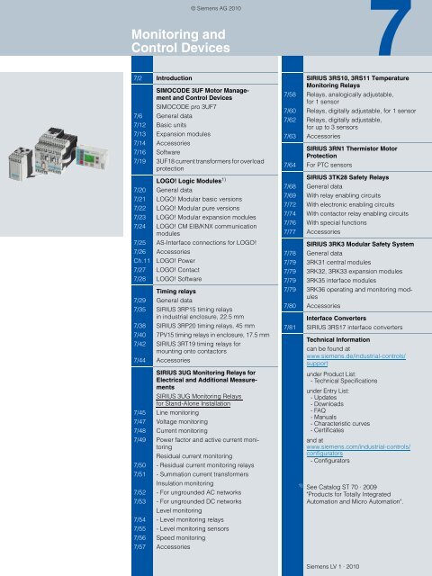
<strong>Monitoring</strong> and<br />
Control Devices<br />
7<br />
7/2 Introduction<br />
SIMOCODE 3UF Motor Management<br />
and Control Devices<br />
SIMOCODE pro 3UF7<br />
7/6 General data<br />
7/12 Basic units<br />
7/13 Expansion modules<br />
7/14 Accessories<br />
7/16 Software<br />
7/19 3UF18 current transformers for overload<br />
protection<br />
LOGO! Logic Modules 1)<br />
7/20 General data<br />
7/21 LOGO! Modular basic versions<br />
7/22 LOGO! Modular pure versions<br />
7/23 LOGO! Modular expansion modules<br />
7/24 LOGO! CM EIB/KNX communication<br />
modules<br />
7/25 AS-Interface connections for LOGO!<br />
7/26 Accessories<br />
Ch.11 LOGO! Power<br />
7/27 LOGO! Contact<br />
7/28 LOGO! Software<br />
Timing relays<br />
7/29 General data<br />
7/35 SIRIUS 3RP15 timing relays<br />
in industrial enclosure, 22.5 mm<br />
7/38 SIRIUS 3RP20 timing relays, 45 mm<br />
7/40 7PV15 timing relays in enclosure, 17.5 mm<br />
7/42 SIRIUS 3RT19 timing relays for<br />
mounting onto contactors<br />
7/44 Accessories<br />
SIRIUS 3UG <strong>Monitoring</strong> <strong>Relay</strong>s for<br />
Electrical and Additional Measurements<br />
SIRIUS 3UG <strong>Monitoring</strong> <strong>Relay</strong>s<br />
for Stand-Alone Installation<br />
7/45 Line monitoring<br />
7/47 Voltage monitoring<br />
7/48 Current monitoring<br />
7/49 Power factor and active current monitoring<br />
Residual current monitoring<br />
7/50 - Residual current monitoring relays<br />
7/51 - Summation current transformers<br />
Insulation monitoring<br />
7/52 - For ungrounded AC networks<br />
7/53 - For ungrounded DC networks<br />
Level monitoring<br />
7/54 - Level monitoring relays<br />
7/55 - Level monitoring sensors<br />
7/56 Speed monitoring<br />
7/57 Accessories<br />
SIRIUS 3RS10, 3RS11 Temperature<br />
<strong>Monitoring</strong> <strong>Relay</strong>s<br />
7/58 <strong>Relay</strong>s, analogically adjustable,<br />
for 1 sensor<br />
7/60 <strong>Relay</strong>s, digitally adjustable, for 1 sensor<br />
7/62 <strong>Relay</strong>s, digitally adjustable,<br />
for up to 3 sensors<br />
7/63 Accessories<br />
SIRIUS 3RN1 Thermistor Motor<br />
Protection<br />
7/64 For PTC sensors<br />
SIRIUS 3TK28 Safety <strong>Relay</strong>s<br />
7/68 General data<br />
7/69 With relay enabling circuits<br />
7/72 With electronic enabling circuits<br />
7/74 With contactor relay enabling circuits<br />
7/76 With special functions<br />
7/77 Accessories<br />
SIRIUS 3RK3 Modular Safety System<br />
7/78 General data<br />
7/79 3RK31 central modules<br />
7/79 3RK32, 3RK33 expansion modules<br />
7/79 3RK35 interface modules<br />
7/79 3RK36 operating and monitoring modules<br />
7/80 Accessories<br />
Interface Converters<br />
7/81 SIRIUS 3RS17 interface converters<br />
Technical Information<br />
can be found at<br />
www.siemens.de/industrial-controls/<br />
support<br />
under Product List:<br />
- Technical Specifications<br />
under Entry List:<br />
- Updates<br />
- Downloads<br />
- FAQ<br />
- Manuals<br />
- Characteristic curves<br />
- Certificates<br />
and at<br />
www.siemens.com/industrial-controls/<br />
configurators<br />
- Configurators<br />
1) See Catalog ST 70 · 2009<br />
"Products for Totally Integrated<br />
Automation and Micro Automation".<br />
Siemens LV 1 · 2010
© Siemens AG 2010<br />
<strong>Monitoring</strong> and Control Devices<br />
Introduction<br />
■ Overview<br />
The advantages at a glance<br />
3UF7<br />
6ED1 052<br />
3RP15<br />
7<br />
Type<br />
Page<br />
SIMOCODE 3UF motor management and control devices<br />
SIMOCODE pro 3UF7<br />
• Compact, modular design<br />
• Unique flexibility in terms of functionality and hardware configuration<br />
• Wide functional range from the distributed I/O system to the<br />
autonomous motor management system<br />
• All control functions from the direct-on-line starter to the<br />
pole-changing switch with reversing contactor<br />
• All motor sizes<br />
• Integration in all PROFIBUS-capable automation systems<br />
• Application in low-voltage controlgear for motor control centers<br />
in the process industry<br />
• Increases plant availability<br />
• Saves costs during construction, commissioning and operation<br />
of the plant<br />
• Extensive data of the motor feeder available everywhere on<br />
the PROFIBUS<br />
• All protection, monitoring and control functions for the motor<br />
feeder in a single system<br />
3UF7 7/6<br />
3UF18 current transformers for overload<br />
protection<br />
LOGO! logic modules<br />
LOGO! logic modules<br />
LOGO! Modular basic versions<br />
LOGO! Modular pure versions<br />
LOGO! Modular expansion modules<br />
LOGO! Modular communication modules<br />
LOGO! Power<br />
LOGO! Contact<br />
• Protection transformer for activating overload relays or for<br />
use with SIMOCODE 3UF<br />
• Ensures proportional current transfer up to a multiple of the<br />
primary rated current<br />
• Compact, user-friendly and low-cost solution for simple<br />
control tasks<br />
• Universal:<br />
- Building installation and wiring (lighting, shutters,<br />
awnings, doors, access control, barriers, ventilation<br />
systems ...)<br />
- Control cabinet installation<br />
- Machine and device construction (pumps, small presses,<br />
compressors, hydraulic lifts, conveyors ...)<br />
- Special controls for conservatories and greenhouses<br />
- Signal preprocessing for other controllers<br />
• Flexible expansion depending on the application<br />
• With display, pushbuttons and an interface for connecting<br />
expansion units<br />
• Without display and pushbuttons but with an interface for<br />
connecting expansion units<br />
• For connection to LOGO! Modular basic versions with<br />
digital inputs and outputs or analog inputs and outputs<br />
• For integrating LOGO! in an instabus KNX EIB system or as<br />
an AS-Interface slave<br />
• Power supply for converting the mains voltage of<br />
100 ... 240 V AC into an operational voltage of 24 V DC or<br />
12 V DC<br />
• Switching module for switching resistive loads and motors<br />
directly<br />
3UF18 7/19<br />
6ED1 052-1 7/21<br />
6ED1 052-2 7/22<br />
6ED1 055-1 7/23<br />
6BK1 700,<br />
3RK1 400<br />
7/24,<br />
7/25<br />
6EP1 3 Ch. 11<br />
6ED1 057-4 7/27<br />
LOGO! Software • For switching program generation on the PC 6ED1 058 7/28<br />
Timing relays<br />
SIRIUS 3RP15 timing relays<br />
in industrial enclosure, 22.5 mm<br />
• Low-cost solution with monofunctions such as response delay,<br />
off-delay, clock-pulse, wye-delta function and multifunc-<br />
3RP15 7/35<br />
tion<br />
• Wide voltage range versions<br />
SIRIUS 3RP20 timing relays, 45 mm • The solution for small mounting depths 3RP20 7/38<br />
• The low mounting height reduces the tier spacing<br />
7PV15 timing relays in enclosure, 17.5 mm • The solution for industry and infrastructure 7PV15 7/40<br />
• Ideal modules for heating, ventilation and air conditioning<br />
systems<br />
• Wide voltage range 12 ... 240 V AC/DC and multifunction for<br />
flexible applications<br />
SIRIUS 3RT19 timing relays<br />
for mounting onto contactors<br />
• Saves space because the relay is mounted onto the<br />
contactor<br />
• Wiring advantages thanks to direct contacting to the<br />
contactor<br />
3RT1916,<br />
3RT19 26<br />
7/42<br />
7/2 Siemens LV 1 · 2010
© Siemens AG 2010<br />
<strong>Monitoring</strong> and Control Devices<br />
Introduction<br />
The advantages at a glance<br />
Type<br />
Page<br />
SIRIUS 3UG monitoring relays for electrical and additional measurements<br />
Line monitoring<br />
Phase sequence • Low-cost solution for monitoring the phase sequence 3UG45 11 7/45<br />
Phase sequence, phase failure, phase unbalance • Wide voltage range from 160 ... 690 V 3UG45 12 7/45<br />
Phase sequence, phase failure, phase unbalance<br />
and undervoltage<br />
Phase sequence, phase failure, phase unbalance<br />
over limit values, overvoltage and undervoltage<br />
Phase sequence, phase and N conductor failure,<br />
phase unbalance over limit values, overvoltage<br />
and undervoltage<br />
Automatic correction of the direction of rotation<br />
in case of wrong phase sequence, phase failure,<br />
phase unbalance, overvoltage and undervoltage<br />
Automatic correction of the direction of rotation<br />
in case of wrong phase sequence, phase and N<br />
conductor failure, phase unbalance, overvoltage<br />
and undervoltage<br />
Voltage monitoring<br />
Voltage monitoring with internal power supply<br />
for overvoltage and undervoltage<br />
Voltage monitoring with auxiliary voltage<br />
for overvoltage and undervoltage<br />
Current monitoring<br />
Current monitoring with auxiliary voltage<br />
for overshoot and undershoot<br />
• Analogically adjustable<br />
• Wide voltage range from 160 ... 690 V<br />
• Digitally adjustable with LCD<br />
for indication of ACTUAL value and device status<br />
• Wide voltage range from 160 ... 690 V<br />
• Digitally adjustable with LCD<br />
for indication of ACTUAL value and device status<br />
• Wide voltage range from 160 ... 690 V<br />
• Digitally adjustable with LCD<br />
for indication of ACTUAL value and device status<br />
• Wide measuring ranges<br />
• Version for wide voltage range<br />
• Digitally adjustable with LCD<br />
for indication of ACTUAL value and device status<br />
• Wide measuring ranges<br />
• Version for wide voltage range<br />
Power factor and active current monitoring (motor load monitoring)<br />
Power factor and active current monitoring with<br />
internal power supply for overshoot, undershoot<br />
or range monitoring<br />
Residual current monitoring<br />
Residual current monitoring relays<br />
• For load monitoring over the entire torque range<br />
• Digitally adjustable with LCD<br />
for indication of ACTUAL value and device status<br />
• Wide voltage range from 90 ... 690 V<br />
• Digitally adjustable with LCD<br />
for indication of ACTUAL value and device status<br />
• Adjustable threshold values for warning and disconnection<br />
• For plant monitoring<br />
• Wide voltage range from 90 ... 690 V<br />
3UG45 13 7/45<br />
3UG46 14 7/45<br />
3UG46 15 7/45<br />
3UG46 16 7/45<br />
3UG46 17 7/45<br />
3UG46 18 7/45<br />
3UG46 33 7/47<br />
3UG46 31,<br />
3UG46 32<br />
3UG46 21,<br />
3UG46 22<br />
7/47<br />
7/48<br />
3UG46 41 7/49<br />
3UG46 24 7/50<br />
Summation current transformers • For detection of fault currents in machines and plants 3UL22 7/51<br />
Insulation monitoring<br />
<strong>Monitoring</strong> of the insulation resistance<br />
for ungrounded AC or DC networks<br />
from 1 to 110 kΩ<br />
Level monitoring<br />
Fill level and resistance<br />
• Test button 3UG30 81,<br />
• With or without memory<br />
3UG30 82<br />
• Switchable measuring range<br />
• As single-step or two-step controls for inlet or outlet monitoring<br />
3UG45 01 7/54<br />
of conducting liquids or as resistance threshold switch<br />
• Adjustable, wide range from 2 ... 200 kΩ<br />
• UNDER/OVER adjustable<br />
Level monitoring sensors • Wire, rod or bow electrodes 3UG32 7/55<br />
Speed monitoring<br />
Speed monitoring for overshoot, undershoot or<br />
range monitoring<br />
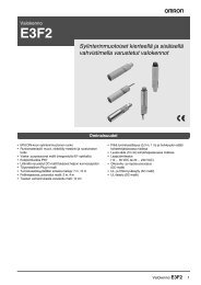
3UG45 11 3UG46 16 3UG46 33<br />
• Digitally adjustable with LCD<br />
for indication of ACTUAL value and device status<br />
• Wide measuring ranges<br />
• Version for wide voltage range<br />
• Together with a sensor for monitoring continuous pulses<br />
• With or without memory<br />
• Adjustable delay times<br />
7/52,<br />
7/53<br />
3UG46 51 7/56<br />
7<br />
Siemens LV 1 · 2010<br />
7/3
© Siemens AG 2010<br />
<strong>Monitoring</strong> and Control Devices<br />
Introduction<br />
The advantages at a glance<br />
3RS10<br />
3RN1<br />
3TK28<br />
7<br />
Type<br />
Page<br />
SIRIUS 3RS10, 3RS11 temperature monitoring relays<br />
For monitoring the temperatures of solids, liquids, and gases<br />
<strong>Relay</strong>s, analog adjustable, for 1 sensor • Separate versions for overshoot and undershoot 3RS10,<br />
7/58<br />
• For simple monitoring tasks<br />
• For PT100 or thermoelements J and K<br />
• Variable hysteresis<br />
3RS11<br />
<strong>Relay</strong>s, digitally adjustable, for 1 sensor • For two-or three-point controls 3RS10,<br />
7/60<br />
,<br />
• For monitoring heat generation plants<br />
• For PT100/1000, KTY83/84, NTC or thermoelements<br />
type J, K, T, E, N, R, S, B<br />
3RS11,<br />
3RS20,<br />
3RS21<br />
<strong>Relay</strong>s, digitally adjustable for up to 3 sensors • For simultaneously monitoring several sensors 3RS10 7/62<br />
• Especially suited for monitoring motor winding temperatures<br />
• For PT100/1000, KTY83/84, NTC<br />
SIRIUS 3RN1 thermistor motor protection<br />
For PTC sensors<br />
• <strong>Relay</strong>s for monitoring motor winding temperatures with type 3RN1 7/64<br />
A PTC sensors<br />
• Integrated with ATEX approval<br />
• Closed-circuit principle<br />
• Depending on the version: with short-circuit and open-circuit<br />
detection, protection against voltage failure, manual/auto/<br />
remote RESET, 1 CO, 1 NO + 1 NC, 2 CO, 1 NO + 1 CO or<br />
2 CO hard gold-plating<br />
SIRIUS 3TK28 safety relays<br />
With relay enabling circuits<br />
With electronic enabling circuits<br />
With contactor relay enabling circuits<br />
With special functions<br />
• Compact design<br />
• Floating safe outputs<br />
• Also suitable for press and punch controls<br />
• Can be used up to an ambient temperature<br />
of max. 70 °C<br />
• Permanent function checking<br />
• No wear because switched electronically<br />
• High switching frequency<br />
• Long electrical endurance<br />
• Evaluation of solid-state sensors<br />
• Sensor lead up to max. 2000 m<br />
• Cascading possible<br />
• Insensitive to vibrations and dirt<br />
• Compact design, low weight<br />
• Approved for the world market<br />
3TK28 2,<br />
3TK28 3<br />
7/69<br />
3TK28 4 7/72<br />
• Enabling circuits, floating<br />
• AC-15/DC-13 switching capacity<br />
• Protective separation<br />
• Long mechanical and electrical endurance<br />
• Certified as a complete unit<br />
• Fault minimization and cost reduction through factory wiring<br />
• Low installation costs<br />
3TK28 5 7/74<br />
• Floating safe outputs<br />
• Signaling outputs for status and diagnostic signals<br />
• Safe standstill monitoring<br />
3TK28 1 7/76<br />
7/4 Siemens LV 1 · 2010
© Siemens AG 2010<br />
<strong>Monitoring</strong> and Control Devices<br />
Introduction<br />
The advantages at a glance<br />
3RK3<br />
3RS17<br />
SIRIUS 3RK3 modular safety system<br />
Freely configurable, modular safety relays<br />
SIRIUS 3RS17 interface converters<br />
Converters for standard signals and<br />
non-standard variables<br />
• More functionality and flexibility through freely configurable<br />
safety logic<br />
• For all safety applications thanks to compliance with the<br />
highest safety requirements (Category 4 according to<br />
EN 954-1, Performance Level e according to ISO 13849-1 or<br />
SIL3 according to IEC 62061)<br />
• Can be used globally<br />
• Modular hardware configuration<br />
• Parameterization by means of software instead of wiring<br />
• Removable terminals for greater plant availability<br />
Type<br />
Page<br />
3RK3 7/78<br />
• All terminals protected against polarity reversing and overvoltage<br />
up to 30 V<br />
• For electrical separation and conversion<br />
of analog signals<br />
• Short-circuit proof outputs<br />
• From 6.2 mm width<br />
• Switchable multi-range converters<br />
• Versions with manual/automatic switch for setpoint selection<br />
• Versions for conversion of analog variables into frequency<br />
3RS17 7/81<br />
■ Options<br />
On the following pages you will find selection tables for monitoring<br />
and control devices.<br />
Screw terminals<br />
Spring-type terminals<br />
The terminals are indicated in the selection and ordering<br />
data by orange backgrounds.<br />
"Increased safety" type of protection EEx e/d according to<br />
ATEX directive 94/9/EC<br />
The communication-capable, modularly designed<br />
SIMOCODE pro motor management system (SIRIUS Motor Management<br />
and Control Devices) protects motors of types of protection<br />
EEx e and EEx d in potentially explosive areas.<br />
ATEX approval for operation in areas subject to explosion<br />
hazard<br />
The SIRIUS 3RN1 thermistor motor protection relay for PTC sensors<br />
is certified according to ATEX Ex II (2) G and GD for gases<br />
and dust.<br />
The SIRIUS SIMOCODE pro 3UF7 motor management system is<br />
certified for the protection of motors in areas subject to explosion<br />
hazard according to<br />
• ATEX Ex I (M2); equipment group I, category M2 (mining)<br />
• ATEX Ex II (2) GD; equipment group II, category 2 in area GD<br />
See Chapter 20 "Appendix" –> "Standards and approvals"–><br />
"Type overview of approved devices for potentially explosive areas<br />
(ATEX explosion protection)".<br />
7<br />
Siemens LV 1 · 2010<br />
7/5
SIMOCODE 3UF Motor Management and Control Devices<br />
SIMOCODE pro 3UF7<br />
General data<br />
© Siemens AG 2010<br />
7<br />
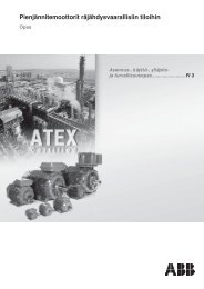
■ Overview<br />
SIMOCODE pro V with current/voltage measuring module,<br />
expansion modules and operator panel with display<br />
SIMOCODE pro is a flexible, modular motor management system<br />
for motors with constant speeds in the low-voltage performance<br />
range. It optimizes the connection between I&C and motor<br />
feeder, increases plant availability and allows significant<br />
savings to be made for startup, operation and maintenance of a<br />
system.<br />
When SIMOCODE pro is installed in the low-voltage switchboard,<br />
it is the intelligent interface between the higher-level automation<br />
system and the motor feeder and includes the following:<br />
• Multifunctional, solid-state full motor protection which is independent<br />
of the automation system<br />
• Integrated control functions instead of hardware for the motor<br />
control<br />
• Detailed operating, service and diagnostics data<br />
• Open communication through PROFIBUS DP, the standard for<br />
fieldbus systems<br />
SIMOCODE ES is the software package for SIMOCODE pro parameterization,<br />
start-up and diagnostics.<br />
Two series<br />
SIMOCODE pro is subdivided into two device series with different<br />
functional scopes:<br />
• SIMOCODE pro C, as a compact system for direct-on-line<br />
starters and reversing starters or actuation of a motor starter<br />
protector or circuit breaker<br />
• SIMOCODE pro V, as a variable system with all control functions<br />
and with the possibility of expanding the inputs, outputs<br />
and functions of the system at will using expansion modules.<br />
Expansion possibilities SIMOCODE pro C,<br />
Basic Unit 1<br />
SIMOCODE pro V,<br />
Basic Unit 2 1)<br />
Operator panels ✓ ✓<br />
Operator panels with display -- ✓<br />
Current measuring modules ✓ ✓<br />
Current/voltage measuring modules<br />
-- ✓<br />
Decoupling modules -- ✓<br />
Expansion modules:<br />
• Digital modules (max. 2)<br />
• Analog module (max. 1)<br />
• Ground-fault module (max. 1)<br />
• Temperature module (max. 1)<br />
✓ Available -- Not available<br />
1) Note: When an operator panel with display and/or a decoupling module is<br />
used, restrictions on the number of expansion modules connectable per<br />
basic unit must be observed, see page 7/9.<br />
--<br />
--<br />
--<br />
--<br />
✓<br />
✓<br />
✓<br />
✓<br />
Per feeder each system always comprises one basic unit and<br />
one separate current measuring module. The two modules are<br />
connected together electrically through the system interface<br />
with a connection cable and can be mounted mechanically connected<br />
as a unit (one behind the other) or separately (side by<br />
side). The motor current to be monitored is decisive only for the<br />
choice of the current measuring module.<br />
An operator panel for mounting in the control cabinet door is optionally<br />
connectable through a second system interface on the<br />
basic unit. Both the current measuring module and the operator<br />
panel are electrically supplied by the basic unit through the connection<br />
cable. More inputs, outputs and functions can be added<br />
to Basic Unit 2 (SIMOCODE pro V) by means of optional expansion<br />
modules, thus supplementing the inputs and outputs already<br />
existing on the basic unit.<br />
All modules are connected by connection cables. The connection<br />
cables are available in various lengths. The maximum distance<br />
between the modules (e. g. between the basic unit and<br />
the current measuring module) must not exceed 2.5 m. The total<br />
length of all the connection cables in a single system must not<br />
be more than 3 m.<br />
■ Benefits<br />
General customer benefits<br />
• Integrating the whole motor feeder into the process control by<br />
means of a bus significantly reduces the wiring outlay between<br />
the motor feeder and PLC<br />
• Decentralization of the automated processes by means of<br />
configurable control and monitoring functions in the feeder<br />
saves resources in the automation system and ensures full<br />
functionality and protection of the feeder even if the I&C or bus<br />
system fails<br />
• The acquisition and monitoring of operational, service and diagnostics<br />
data in the feeder and process control system increases<br />
plant availability as well as maintenance and servicefriendliness<br />
• The high degree of modularity allows users to perfectly implement<br />
their plant-specific requirements for each motor feeder<br />
• The SIMOCODE pro system offers functionally graded and<br />
space-saving solutions for each customer application<br />
• The replacement of the control circuit hardware with integrated<br />
control functions decreases the number of hardware<br />
components and wiring required and in this way limits stock<br />
keeping costs and potential wiring errors<br />
• The use of solid-state full motor protection permits better utilization<br />
of the motors and ensures long-term stability of the tripping<br />
characteristic and reliable tripping even after years of<br />
service<br />
Multifunctional, solid-state full motor protection<br />
for rated motor currents up to 820 A<br />
SIMOCODE pro offers comprehensive protection of the motor<br />
feeder by means of a combination of different, multi-step and delayable<br />
protection and monitoring functions:<br />
• Inverse-time delayed solid-state overload protection<br />
(Class 5 ... 40)<br />
• Thermistor motor protection<br />
• Phase failure/unbalance protection<br />
• Stall protection<br />
• <strong>Monitoring</strong> of adjustable limit values for the motor current<br />
• Voltage and power monitoring<br />
• <strong>Monitoring</strong> of the power factor (motor idling/load shedding)<br />
• Ground-fault monitoring<br />
• Temperature monitoring, e. g. over PT100/PT1000<br />
• <strong>Monitoring</strong> of operating hours, downtime and number of starts<br />
etc.<br />
7/6 Siemens LV 1 · 2010
© Siemens AG 2010<br />
SIMOCODE 3UF Motor Management and Control Devices<br />
SIMOCODE pro 3UF7<br />
General data<br />
Recording of measuring curves<br />
SIMOCODE pro can record measuring curves and therefore is<br />
able, for example, to present the progression of motor current<br />
during motor start-up.<br />
Flexible motor control implemented with integrated control<br />
functions (instead of comprehensive hardware interlocks)<br />
Many predefined motor control functions have already been integrated<br />
into SIMOCODE pro, including all necessary logic operations<br />
and interlocks:<br />
• Overload relays<br />
• Direct-on-line and reversing starters<br />
• Wye/delta starters (also with direction reversal)<br />
• Two speeds, motors with separate windings (pole-changing<br />
switch); also with direction reversal<br />
• Two speeds, motors with separate Dahlander windings (also<br />
with direction reversal)<br />
• Positioner actuation<br />
• Solenoid valve actuation<br />
• Actuation of a circuit breaker<br />
• Soft starter actuation, also with direction reversal.<br />
These control functions are predefined in SIMOCODE pro and<br />
can be freely assigned to the inputs and outputs of the device<br />
(including PROFIBUS DP).<br />
These predefined control functions can also be flexibly adapted<br />
to each customized configuration of a motor feeder by means of<br />
freely configurable logic modules (truth tables, counters, timers,<br />
edge evaluation ...) and with the help of standard functions<br />
(power failure monitoring, emergency start, external faults ...),<br />
without additional auxiliary relays being necessary in the control<br />
circuit.<br />
SIMOCODE pro makes a lot of additional hardware and wiring in<br />
the control circuit unnecessary which results in a high level of<br />
standardization of the motor feeder in terms of its design and circuit<br />
diagrams.<br />
Detailed operational, service and diagnostics data<br />
SIMOCODE pro makes different operational, service and diagnostics<br />
data available and helps to detect potential faults in time<br />
and to prevent them by means of preventative measures. In the<br />
event of a malfunction, a fault can be diagnosed, localized and<br />
rectified very quickly - there are no or very short downtimes.<br />
Operating data<br />
• Motor switching state derived from the current flow in the main<br />
circuit<br />
• All phase currents<br />
• All phase voltages and phase-to-phase voltages<br />
• Active power, apparent power and power factor<br />
• Phase unbalance and phase sequence<br />
• Time to trip<br />
• Motor temperature<br />
• Remaining cooling time etc.<br />
Service data<br />
• Motor operating hours<br />
• Motor stop times<br />
• Number of motor starts<br />
• Number of overload trips<br />
• Consumed power<br />
• Internal comments stored in the device etc.<br />
Diagnostics data<br />
• Numerous detailed early warning and fault messages<br />
• Internal device fault logging with time stamp<br />
• Time stamping of freely selectable status, alarm or fault messages<br />
etc.<br />
Easy operation and diagnostics<br />
Operator panels<br />
The operator panel is used to control the motor feeder and can<br />
replace all conventional pushbuttons and indicator lights to save<br />
space. This means that SIMOCODE pro or the feeder can be operated<br />
directly at the control cabinet. The operator panel also<br />
has all the status LEDs found on the basic unit and connects the<br />
system interface externally for easier parameterization or diagnostics<br />
using a PC or programming device, for example.<br />
Operator panels with display<br />
As an alternative to the 3UF7 20 standard operator panel for<br />
SIMOCODE pro V there is also an operator panel with display:<br />
the 3UF7 21 is thus able in addition to indicate current measured<br />
values, operational and diagnostics data or status information of<br />
the motor feeder at the control cabinet. The pushbuttons of the<br />
operator panel can be used to control the motor while at the<br />
same time the display indicates current measured values, status<br />
information, fault messages or the device-internal fault protocol.<br />
Using the display settings each user can select for himself how<br />
the measured values are presented as standard and how the<br />
displayed unit is converted (e. g. °C -> °F).<br />
Communication<br />
SIMOCODE pro is equipped with an integral PROFIBUS DP interface<br />
(SUB-D or terminal connection) and can therefore replace<br />
all individual wiring (including marshalling racks), which<br />
would usually be required for exchanging data with the higherlevel<br />
automation system, with a single 2-wire cable.<br />
SIMOCODE pro supports among other things:<br />
• Baud rates up to 12 Mbit/s<br />
• Automatic baud rate detection<br />
• Communication with up to 3 masters<br />
• Time synchronization over PROFIBUS (SIMATIC S7)<br />
• Time stamp with high timing precision (SIMATIC S7)<br />
• Cyclic services (DPV0) and acyclic services (DPV1)<br />
• DPV1 communication after the Y-Link etc.<br />
For SIMOCODE pro motor management and control devices<br />
with communication function see page 7/12 onwards.<br />
For accessories, see page 7/14 onwards.<br />
For more information see also Chapter 12 "Planning, Configuration<br />
and Visualizing for SIRIUS".<br />
For accessories for PROFIBUS DP see Catalog IK PI "Industrial<br />
Communication".<br />
Autonomous operation<br />
An essential feature of SIMOCODE pro is independent execution<br />
of all protection and control functions even if communication<br />
with the I&C system breaks down. If the bus or automation system<br />
fails, the full functionality of the feeder is ensured or a predefined<br />
response can be initiated, e. g. the feeder can be shut<br />
down in a controlled manner or certain configured control mechanisms<br />
can be performed (e. g. the direction of rotation can be<br />
reversed).<br />
SIMOCODE pro designed for mixed operation<br />
Depending on functional requirements, the two systems can be<br />
used simultaneously without any problems and without any additional<br />
outlay in a low-voltage system. SIMOCODE pro C is fully<br />
upward-compatible to SIMOCODE pro V. The same components<br />
are used. The parameterization of SIMOCODE pro C can<br />
be transferred without any problems. Both systems have the<br />
same removable terminals and the same terminal designations.<br />
7<br />
Siemens LV 1 · 2010<br />
7/7
SIMOCODE 3UF Motor Management and Control Devices<br />
SIMOCODE pro 3UF7<br />
General data<br />
© Siemens AG 2010<br />
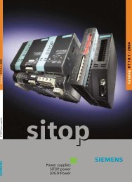
Main circuit<br />
Control circuit<br />
Automation level<br />
L1<br />
L2<br />
L3<br />
-Q1<br />
PROFIBUS DP<br />
-K1 -K2<br />
SIMOCODE pro<br />
Operator panel<br />
Connection cable<br />
NSA0_00398<br />
Current measuring module<br />
Basic unit<br />
-K1 -K2<br />
0<br />
Remote<br />
M<br />
3~<br />
Protect and monitor<br />
(overload, thermistor, earth fault detection ...)<br />
Motor control<br />
(incl. monitoring + interlocking)<br />
Communication<br />
(operational, service, diagnostics data<br />
+ control commands)<br />
SIMOCODE pro combines all the necessary functions for the motor feeder in a compact system.<br />
7<br />
■ Application<br />
SIMOCODE pro is often used for automated processes where<br />
plant downtimes are very expensive (e. g. steel or cement industry)<br />
and where it is important to prevent plant downtimes through<br />
detailed operational, service and diagnostics data or to localize<br />
the fault very quickly in the event of a fault.<br />
SIMOCODE pro is modular and space-saving and suited especially<br />
for operation in motor control centers in the process industry<br />
and for power plant technology.<br />
Applications<br />
Protection and control of motors<br />
• In hazardous areas for types of protection<br />
EEx e/d according to ATEX directive 94/9/EC<br />
see Chapter 20 "Appendix" --> "Standards and approvals" --><br />
"Type overview of approved devices for explosion-protected<br />
areas (ATEX Explosion Protection)".<br />
• With heavy starting (paper, cement, metal and water industries)<br />
• In high-availability plants (chemical, oil, raw material processing<br />
industry, power plants)<br />
Industries<br />
Today, SIMOCODE pro is mainly used in the chemical (incl. oil<br />
and gas), steel, water, paper, pharmaceutical, cement, and<br />
glass industry. It is also used for applications in power plants<br />
and large diamond, gold and platinum mines. Based on the experience<br />
made with the predecessor system SIMOCODE-DP,<br />
SIMOCODE pro has been tailored even more specifically to the<br />
requirements of these industries.<br />
An essential requirement in these industries is the availability of<br />
the motors and thus the availability of the whole process. Plant<br />
downtimes caused by faults frequently result in high costs. For<br />
this reason, it is very important to detect potential faults early on<br />
and to initiate targeted countermeasures. SIMOCODE pro offers<br />
users an up-to-date motor management system based on years<br />
of experience.<br />
7/8 Siemens LV 1 · 2010
© Siemens AG 2010<br />
SIMOCODE 3UF Motor Management and Control Devices<br />
SIMOCODE pro 3UF7<br />
General data<br />
■ More information<br />
Configuration instructions when using an operator panel<br />
with display and/or a decoupling module<br />
If you want to use an operator panel with display and/or a decoupling<br />
module in the SIMOCODE pro V system, then the following<br />
configuration instructions concerning the type and number of<br />
connectable expansion modules must be observed.<br />
The following tables show the maximum possible configuration<br />
of the expansion modules for the various combinations.<br />
Use of an operator panel with display<br />
Digital<br />
modules<br />
Digital<br />
modules<br />
Analog<br />
modules<br />
Temperature<br />
modules<br />
Use of a decoupling module<br />
(voltage measurement in insulated networks)<br />
Use of a decoupling module<br />
(voltage measurement in insulated networks)<br />
in combination with an operator panel with display<br />
Ground-fault<br />
modules<br />
Only operator panel with display for Basic Unit 2<br />
(24 V DC or 110 ... 240 V AC/DC)<br />
Max. 4 expansion modules can be used<br />
Operator panel with display and current/voltage measurement<br />
with Basic Unit 2 (110 ... 240 V AC/DC)<br />
Max. 3 expansion modules can be used or:<br />
-- -- ✓ ✓ --<br />
Digital<br />
modules<br />
Digital<br />
modules<br />
Analog<br />
modules<br />
Temperature<br />
modules<br />
Ground-fault<br />
modules<br />
Basic Unit 2 (24 V DC)<br />
✓ 1) ✓ 1) ✓ ✓ ✓<br />
Basic Unit 2 (110 ... 240 V AC/DC)<br />
✓ ✓ -- ✓ ✓<br />
✓ 1) ✓ 1) ✓ ✓ --<br />
✓ -- ✓ ✓ --<br />
✓ -- ✓ -- ✓<br />
Digital Digital Analog Temperature Ground-fault<br />
modules modules modules modules modules<br />
Basic Unit 2 (24 V DC)<br />
✓ -- ✓ ✓ ✓<br />
✓ ✓ -- ✓ ✓<br />
Basic Unit 2 (110 ... 240 V AC/DC)<br />
✓ 2) -- ✓ ✓ ✓<br />
✓ ✓ -- -- --<br />
✓ 1) ✓ 1) ✓ 3) -- --<br />
✓ -- -- ✓ ✓<br />
✓ Available<br />
-- Not available<br />
1) No bistable relay outputs and no more than 5 of 7 relay outputs active<br />
simultaneously (> 3 s).<br />
2) No bistable relay outputs and no more than 3 of 5 relay outputs active<br />
simultaneously (> 3 s).<br />
3) Analog module output is not used.<br />
Protective separation<br />
All circuits in SIMOCODE pro are safely separated from each<br />
other according to IEC 60947-1, Annex N. That is, they are designed<br />
with double creepages and clearances. In the event of a<br />
fault, therefore, no parasitic voltages can be formed in neighboring<br />
circuits. The instructions of Test Report No. 2668 must be<br />
complied with.<br />
EEx e and EEx d types of protection<br />
The overload protection and the thermistor motor protection<br />
of the SIMOCODE pro system comply with the requirements for<br />
overload protection of explosion-protected motors to the type of<br />
protection:<br />
• EEx d "flameproof enclosure" e. g. according to EN 50018 or<br />
EN 60079-1<br />
• EEx e "increased safety" e. g. according to EN 50019 or<br />
EN 60079-7.<br />
When using SIMOCODE pro devices with a 24 V DC control voltage,<br />
electrical separation must be ensured using a battery or a<br />
safety transformer according to EN 61558-2-6.<br />
EC type test certificate: BVS 06 ATEX F 001<br />
Test log: BVS PP 05.2029 EG.<br />
Selection data for type-tested assemblies/load feeders<br />
Configuration tables according to type of coordination 1 or 2 can<br />
be found in the manual "SIRIUS Configuration", Order No.:<br />
E86060-T1815-A101-A3 or in the SIMOCODE pro System Manual.<br />
System manual<br />
The SIMOCODE pro system manual describes the motor management<br />
system and its functions in detail. It contains information<br />
about configuration and commissioning as well as for servicing<br />
and maintenance. A typical example of a reversing starter<br />
application is used to teach the user quickly and practically how<br />
to use the system. In addition to help on how to identify and rectify<br />
faults in the event of a malfunction, the manual also contains<br />
special information for servicing and maintenance. For selection<br />
of equipment and for configuration, it is recommended that the<br />
3UF7 970-0AA0.-0 system manual is consulted.<br />
Internet<br />
You can find further information on the Internet at:<br />
www.siemens.com/simocode<br />
7<br />
Siemens LV 1 · 2010<br />
7/9
SIMOCODE 3UF Motor Management and Control Devices<br />
SIMOCODE pro 3UF7<br />
General data<br />
© Siemens AG 2010<br />
7<br />
Technical specifications<br />
General technical specifications<br />
Permissible ambient temperature<br />
• During operation °C -25 ... +60 ; 3UF7 21: 0 ... +60<br />
• Storage and transport °C -40 ... +80 ; 3UF7 21: -20 ... +70<br />
Degree of protection (acc. to IEC 60529)<br />
• Measuring modules with busbar connection<br />
IP00<br />
• Operator panel (front) and door adapter (front) with cover<br />
IP54<br />
• Other components<br />
IP20<br />
Shock resistance (sine pulse) g/ms 15/11<br />
Mounting position<br />
Any<br />
Frequency Hz 50/60 ±5 %<br />
Immunity to electromagnetic interference (acc. to IEC 60947-1) Corresponds to degree of severity 3<br />
• Line-induced interference, burst acc. to IEC 61000-4-4<br />
kV<br />
kV<br />
2 (power ports)<br />
1 (signal ports)<br />
• Line-induced interference, high frequency acc. to<br />
V 10<br />
IEC 61000-4-6<br />
• Line-induced interference, surge acc. to IEC 61000-4-5<br />
kV 2 (line to earth)<br />
kV 1 (line to line)<br />
• Electrostatic discharge, ESD acc. to IEC 61000-4-2<br />
kV<br />
kV<br />
• Field-related interference acc. to IEC 61000-4-3 V/m 10<br />
8 (air discharge)<br />
6 (contact discharge); 3UF7 21: 4 (contact discharge)<br />
Immunity to electromagnetic interference (acc. to IEC 60947-1)<br />
• Line-conducted and radiated interference emission EN 55011/ EN 55022 (CISPR 11/CISPR 22)<br />
(corresponds to degree of severity A)<br />
Protective separation (acc. to IEC 60947-1, Annex N)<br />
All circuits in SIMOCODE pro are safely separated from each other acc. to<br />
IEC 60947-1, they are designed with doubled creepage paths and clearances<br />
In this context, compliance with the instructions in the test report<br />
"Protective separation" No. 2668 is required.<br />
Basic units<br />
Control circuit<br />
Rated control supply voltage U s (acc. to EN 61131-2) 110 ... 240 V AC/DC; 50/60 Hz 24 V DC<br />
Operating range 0.85 ... 1.1 x U s 0.80 ... 1.2 × U s<br />
Power consumption<br />
• Basic Unit 1 (3UF7 000) 7VA/5 W 5W<br />
• Basic Unit 2 (3UF7 010)<br />
10 VA/7 W 7W<br />
incl. two expansion modules connected to Basic Unit 2<br />
Rated insulation voltage U i V 300 (at pollution degree 3)<br />
Rated impulse withstand voltage U imp kV 4<br />
<strong>Relay</strong> outputs<br />
•Number<br />
3 monostable relay outputs<br />
• Specified short-circuit protection for auxiliary contacts<br />
(relay outputs)<br />
• Fuse links, gL/gA operational class 6 A, quick-acting 10 A (IEC 60947-5-1)<br />
• Miniature circuit breaker 1.6 A, C characteristic (IEC 60947-5-1)<br />
• Miniature circuit breaker 6 A, C characteristic (I k
© Siemens AG 2010<br />
SIMOCODE 3UF Motor Management and Control Devices<br />
SIMOCODE pro 3UF7<br />
General data<br />
Current measuring modules or current/voltage measuring modules<br />
(continued)<br />
Notes on voltage measurement<br />
• In insulated, high-resistance or asymmetrically grounded forms of<br />
power supply system and for single-phase systems<br />
• Feeder lines for voltage measurement<br />
Digital modules<br />
Control circuit<br />
Rated insulation voltage U i V 300 (at pollution degree 3)<br />
Rated impulse withstand voltage U imp kV 4<br />
<strong>Relay</strong> outputs<br />
•Number<br />
• Specified short-circuit protection for auxiliary contacts<br />
(relay outputs)<br />
✓ Detection possible<br />
In these networks the current/voltage measuring module can be used only<br />
with an upstream decoupling module on the system interface.<br />
In the feeder lines from the main circuit for voltage measurement of<br />
SIMOCODE pro it may be necessary to provide additional line protection!<br />
2 monostable or bistable relay outputs (depending on the version)<br />
• Fuse links, gL/gG operational class 6 A, quick-acting 10 A (IEC 60947-5-1)<br />
• Miniature circuit breaker 1.6 A, C characteristic (IEC 60947-5-1)<br />
• Miniature circuit breaker 6 A, C characteristic (I k
SIMOCODE 3UF Motor Management and Control Devices<br />
SIMOCODE pro 3UF7<br />
Basic units<br />
■ Selection and ordering data<br />
© Siemens AG 2010<br />
SIMOCODE pro<br />
Version<br />
Current<br />
setting<br />
SIMOCODE pro C, Basic Unit 1<br />
PROFIBUS DP interface, 12 Mbit/s, RS 485<br />
4 I/3 O freely assignable, input for thermistor<br />
connection, monostable relay outputs,<br />
rated control supply voltage U s :<br />
Width DT Screw terminals PU<br />
(UNIT,<br />
SET, M)<br />
Order No.<br />
Price<br />
per PU<br />
PS* PG Weight<br />
per PU<br />
approx.<br />
A mm kg<br />
•24VDC A 3UF7 000-1AB00-0 1 1 unit 131 0.350<br />
• 110 ... 240 V AC/DC A 3UF7 000-1AU00-0 1 1 unit 131 0.350<br />
3UF7 000-1A.00-0<br />
SIMOCODE pro V, Basic Unit 2<br />
PROFIBUS DP interface, 12 Mbit/s, RS 485<br />
4 I/3 O freely assignable, input for thermistor<br />
connection, monostable relay outputs, can be<br />
expanded by expansion modules<br />
rated control supply voltage U s :<br />
•24VDC A 3UF7 010-1AB00-0 1 1 unit 131 0.350<br />
• 110 ... 240 V AC/DC A 3UF7 010-1AU00-0 1 1 unit 131 0.350<br />
7<br />
3UF7 010-1A.00-0<br />
3UF7 100-1AA00-0<br />
3UF7 110-1AA00-0<br />
Current measuring modules<br />
Straight-through transformers<br />
0.3 ... 3 45 A 3UF7 100-1AA00-0 1 1 unit 131 0.100<br />
2.4 ... 25 45 A 3UF7 101-1AA00-0 1 1 unit 131 0.150<br />
10 ... 100 55 A 3UF7 102-1AA00-0 1 1 unit 131 0.350<br />
20 ... 200 120 A 3UF7 103-1AA00-0 1 1 unit 131 0.600<br />
Busbar connections 20 ... 200 120 A 3UF7 103-1BA00-0 1 1 unit 131 1.000<br />
63 ... 630 145 A 3UF7 104-1BA00-0 1 1 unit 131 1.750<br />
Current/voltage measuring modules<br />
For SIMOCODE pro V<br />
Voltage measuring up to 690 V<br />
if required in connection with a decoupling module<br />
Straight-through transformers<br />
0.3 ... 3 45 A 3UF7 110-1AA00-0 1 1 unit 131 0.150<br />
2.4 ... 25 45 A 3UF7 111-1AA00-0 1 1 unit 131 0.200<br />
10 ... 100 55 A 3UF7 112-1AA00-0 1 1 unit 131 0.400<br />
20 ... 200 120 A 3UF7 113-1AA00-0 1 1 unit 131 0.700<br />
Busbar connections 20 ... 200 120 A 3UF7 113-1BA00-0 1 1 unit 131 1.000<br />
63 ... 630 145 A 3UF7 114-1BA00-0 1 1 unit 131 1.750<br />
Decoupling modules<br />
For connecting upstream from a current/voltage A 3UF7 150-1AA00-0 1 1 unit 131 0.150<br />
measuring module on the system interface<br />
when using voltage detection in insulated, highresistance<br />
or asymmetrically grounded systems<br />
and in single-phase systems<br />
3UF7 150-1AA00-0<br />
Operator panels<br />
Installation in control cabinet door or front plate,<br />
for plugging into basic unit, 10 LEDs for status<br />
indication and user-assignable buttons for controlling<br />
the motor<br />
A 3UF7 200-1AA00-0 1 1 unit 131 0.100<br />
3UF7 200-1AA00-0<br />
3UF7 210-1AA00-0<br />
1) Only possible with Basic Unit 2, product version E03 and higher (from<br />
12/2006).<br />
7/12 Siemens LV 1 · 2010<br />
Operator panels with display for SIMOCODE<br />
pro V 1)<br />
Installation in control cabinet door or front plate,<br />
for plugging into Basic Unit 2, 7 LEDs for status<br />
indication and user-assignable buttons for controlling<br />
the motor, multilingual display, e. g. for<br />
indication of measured values, status information<br />
or fault messages<br />
} 3UF7 210-1AA00-0 1 1 unit 131 0.150<br />
* You can order this quantity or a multiple thereof.
© Siemens AG 2010<br />
SIMOCODE 3UF Motor Management and Control Devices<br />
SIMOCODE pro 3UF7<br />
Expansion modules<br />
■ Selection and ordering data<br />
Version DT Screw terminals PU<br />
(UNIT,<br />
SET, M)<br />
Order No.<br />
Price<br />
per PU<br />
PS* PG Weight<br />
per PU<br />
approx.<br />
kg<br />
Expansion modules for SIMOCODE pro V<br />
With SIMOCODE pro V, it is possible to expand the type and number of<br />
inputs and outputs in steps. Each expansion module has two system interfaces<br />
on the front. Through the one system interface the expansion module is<br />
connected to the system interface of the SIMOCODE pro V using a connection<br />
cable; through the second system interface, further expansion modules<br />
or the operator panel can be connected. The power supply for the expansion<br />
modules is provided by the connection cable through Basic Unit 2.<br />
Important: Please order connection cable separately, see page 7/14!<br />
Digital modules<br />
Up to two digital modules can be used to add<br />
additional binary inputs and relay outputs to<br />
basic unit. The input circuits of the digital modules<br />
are supplied from an external power supply.<br />
4 binary inputs and 2 relay outputs,<br />
Up to 2 digital modules can be connected per<br />
Basic Unit 2<br />
<strong>Relay</strong> outputs<br />
Input voltage<br />
3UF7 300-1AU00-0<br />
Monostable 24 V DC A 3UF7 300-1AB00-0 1 1 unit 131 0.150<br />
110 ... 240 V AC/DC A 3UF7 300-1AU00-0 1 1 unit 131 0.150<br />
Bistable 24 V DC A 3UF7 310-1AB00-0 1 1 unit 131 0.150<br />
110 ... 240 V AC/DC A 3UF7 310-1AU00-0 1 1 unit 131 0.150<br />
Analog modules<br />
Basic Unit 2 can be optionally expanded with<br />
analog inputs and outputs (0/4 ... 20 mA) by<br />
means of the analog module.<br />
2 inputs (passive) for input<br />
and 1 output for output of 0/4 ... 20 mA signals,<br />
max. 1 analog module can be connected per<br />
Basic Unit 2<br />
A 3UF7 400-1AA00-0 1 1 unit 131 0.150<br />
3UF7 400-1AA00-0<br />
3UF7 500-1AA00-0<br />
3UF7 700-1AA00-0<br />
Ground-fault modules<br />
Instead of ground-fault monitoring using the current<br />
measuring modules or current/voltage measuring<br />
modules, it may be necessary, especially<br />
in high-impedance grounded networks, to implement<br />
ground-fault monitoring for smaller ground<br />
fault currents using a summation current transformer.<br />
1 input for connecting<br />
a summation current transformer 3UL22,<br />
up to 1 ground-fault module can be connected<br />
per Basic Unit 2<br />
Note:<br />
For the corresponding summation current transformers<br />
for rated fault currents of 0.3 A, 0.5 A or<br />
1 A see page 7/51.<br />
A 3UF7 500-1AA00-0 1 1 unit 131 0.150<br />
Temperature modules<br />
Independently of the thermistor motor protection<br />
of the basic units, up to 3 analog temperature<br />
sensors can be evaluated using a temperature<br />
module.<br />
Sensor types: PT100/PT1000, KTY83/KTY84 or<br />
NTC<br />
3 inputs for connecting<br />
up to 3 analog temperature sensors, up<br />
to 1 temperature module can be connected per<br />
Basic Unit 2<br />
A 3UF7 700-1AA00-0 1 1 unit 131 0.150<br />
7<br />
* You can order this quantity or a multiple thereof.<br />
Siemens LV 1 · 2010<br />
7/13
SIMOCODE 3UF Motor Management and Control Devices<br />
SIMOCODE pro 3UF7<br />
Accessories<br />
© Siemens AG 2010<br />
■ Selection and ordering data<br />
Version DT Order No. Price<br />
per PU<br />
Connection cables (essential accessory)<br />
3UF7 932-0AA00-0<br />
PU<br />
(UNIT,<br />
SET, M)<br />
PS* PG Weight<br />
per PU<br />
approx.<br />
kg<br />
Connection cables<br />
In different lengths for connecting basic unit, current<br />
measuring module, current/voltage measuring<br />
module, operator panel or expansion modules or<br />
decoupling module:<br />
• Length 0.025 m (flat)<br />
Note: Only suitable for connecting Basic Unit 2<br />
to its expansion modules or for connecting expansion<br />
modules to each other; only when the front<br />
plates finish at the same height!<br />
A 3UF7 930-0AA00-0 1 1 unit 131 0.010<br />
• Length 0.1 m (flat) A 3UF7 931-0AA00-0 1 1 unit 131 0.010<br />
• Length 0.3 m (flat) A 3UF7 935-0AA00-0 1 1 unit 131 0.020<br />
• Length 0.5 m (flat) A 3UF7 932-0AA00-0 1 1 unit 131 0.020<br />
• Length 0.5 m (round) A 3UF7 932-0BA00-0 1 1 unit 131 0.050<br />
• Length 1.0 m (round) A 3UF7 937-0BA00-0 1 1 unit 131 0.100<br />
• Length 2.5 m (round) A 3UF7 933-0BA00-0 1 1 unit 131 0.150<br />
PC cables and adapters<br />
3UF7 940-0AA00-0<br />
Memory modules<br />
3UF7 900-0AA00-0<br />
For PC/PG communication with SIMOCODE pro<br />
Through the system interface, for connecting to<br />
the serial interface of the PC/PG<br />
USB/serial adapters<br />
To connect an RS 232 PC cable to the USB port of<br />
a PC, we recommend using 3RK3 modular safety<br />
system, 3RW44 soft starter,<br />
ET 200S/ECOFAST/ET 200pro motor starter,<br />
AS-i safety monitor, AS-i analyzer in conjunction<br />
with SIMOCODE pro 3UF7<br />
The memory module enables the complete parameter<br />
assignment of a system to be saved and transferred<br />
to a new system, e. g. when a device is<br />
replaced, without the need for additional aids or<br />
detailed knowledge of the the system interface<br />
A 3UF7 940-0AA00-0 1 1 unit 131 0.150<br />
B 3UF7 946-0AA00-0 1 1 unit 131 0.150<br />
A 3UF7 900-0AA00-0 1 1 unit 131 0.010<br />
Interface covers<br />
For system interface A 3UF7 950-0AA00-0 1 5 units 131 0.100<br />
3UF7 950-0AA00-0<br />
7<br />
Addressing plugs<br />
For assigning the PROFIBUS addresses without<br />
using a PC or programming device<br />
On SIMOCODE pro through the system interface<br />
A 3UF7 910-0AA00-0 1 1 unit 131 0.030<br />
3UF7 910-0AA00-0<br />
Door adapters<br />
For external connection of the system interface<br />
Outside, for example, a control cabinet<br />
A 3UF7 920-0AA00-0 1 1 unit 131 0.030<br />
3UF7 920-0AA00-0<br />
Adapters for operator panel<br />
The adapter enables the smaller 3UF7 20 operator<br />
panel from SIMOCODE pro to be used in a front<br />
panel cutout in which previously, e. g. after a<br />
change of system, a larger 3UF5 2 operator panel<br />
from SIMOCODE-DP had been used; degree of<br />
protection IP54<br />
A 3UF7 922-0AA00-0 1 1 unit 131 0.150<br />
3UF7 922-0AA00-0<br />
7/14 Siemens LV 1 · 2010<br />
* You can order this quantity or a multiple thereof.
© Siemens AG 2010<br />
SIMOCODE 3UF Motor Management and Control Devices<br />
SIMOCODE pro 3UF7<br />
Accessories<br />
Labeling strips<br />
3UF7 925-0AA02-0<br />
Version DT Order No. Price<br />
per PU<br />
PU<br />
(UNIT,<br />
SET, M)<br />
PS* PG Weight<br />
per PU<br />
approx.<br />
kg<br />
• For pushbuttons of the 3UF7 20 operator panel A 3UF7 925-0AA00-0 100 400 units 131 15.000<br />
• For pushbuttons of the 3UF7 21 operator panel A 3UF7 925-0AA01-0 100 600 units 131 15.000<br />
with display<br />
• For LEDs of the 3UF7 20 operator panel A 3UF7 925-0AA02-0 100 1200 units 131 15.000<br />
Note: Pre-punched labeling strips for user-specific<br />
printing using the free inscription software<br />
"SIRIUS Label Designer" on a laser printer.<br />
Note the software version!<br />
Download from www.siemens.com/simocode<br />
Push-in lugs<br />
3RB19 00-0B<br />
Terminal covers<br />
For screw fixing<br />
e. g. on mounting plate, 2 units required per device<br />
• Can be used with 3UF7 1.0, 3UF7 1.1 and<br />
3UF7 1.2<br />
• Can be used with 3UF7 0, 3UF7 3, 3UF7 4, 3UF7 5<br />
and 3UF7 7<br />
Covers for cable lugs and busbar connections<br />
A 3RB19 00-0B 100 10 units 101 0.100<br />
} 3RP19 03 1 10 units 101 0.002<br />
• Length 100 mm, can be used for<br />
} 3RT19 56-4EA1 1 1 unit 101 0.070<br />
3UF7 1.3-1BA00-0<br />
• Length 120 mm, can be used for<br />
} 3RT19 66-4EA1 1 1 unit 101 0.130<br />
3UF7 1.4-1BA00-0<br />
3RT19 56-4EA1 Covers for box terminals<br />
• Length 25 mm, can be used for 3UF7 1.3-1BA00-0 } 3RT19 56-4EA2 1 1 unit 101 0.030<br />
• Length 30 mm, can be used for 3UF7 1.4-1BA00-0 } 3RT19 66-4EA2 1 1 unit 101 0.040<br />
Covers for screw terminals<br />
Between contactor and current measuring module<br />
or current/voltage measuring module for direct<br />
3RT19 56-4EA2 mounting<br />
• Can be used for 3UF7 1.3-1BA00-0 } 3RT19 56-4EA3 1 1 unit 101 0.020<br />
• Can be used for 3UF7 1.4-1BA00-0 } 3RT19 66-4EA3 1 1 unit 101 0.060<br />
Box terminal blocks<br />
For round and ribbon cables<br />
• Up to 70 mm 2 , can be used for 3UF7 1.3-1BA00-0 } 3RT19 55-4G 1 1 unit 101 0.230<br />
• Up to 120 mm 2 , can be used for 3UF7 1.3-1BA00-0 } 3RT19 56-4G 1 1 unit 101 0.260<br />
• Up to 240 mm 2 , can be used for 3UF7 1.4-1BA00-0 } 3RT19 66-4G 1 1 unit 101 0.676<br />
For conductor cross-sections see note on Technical<br />
Information on page 7/1.<br />
7<br />
3RT19 5.-4G<br />
Bus terminations<br />
System manuals<br />
Bus termination module with separate supply voltage for<br />
terminating the bus following the last unit on the bus line.<br />
Supply voltage:<br />
• 115/230 V AC C 3UF1 900-1KA00 1 1 unit 131 0.286<br />
• 24 V DC C 3UF1 900-1KB00 1 1 unit 131 0.192<br />
SIMOCODE pro<br />
With token fee,<br />
languages:<br />
•German A 3UF7 970-0AA01-0 1 1 unit 131 0.850<br />
• English A 3UF7 970-0AA00-0 1 1 unit 131 0.850<br />
•French A 3UF7 970-0AA02-0 1 1 unit 131 0.850<br />
3UF7 970-0AA01-0<br />
* You can order this quantity or a multiple thereof.<br />
Siemens LV 1 · 2010<br />
7/15
SIMOCODE 3UF Motor Management and Control Devices<br />
SIMOCODE pro 3UF7<br />
Software<br />
© Siemens AG 2010<br />
7<br />
■ Overview<br />
General<br />
In addition to device function and hardware design, a great deal<br />
of emphasis is placed on the case of communication-capable<br />
controls on the user-friendliness of the parameterization software<br />
and the ability of the system to be integrated easily into various<br />
different system configurations and process automation systems.<br />
For this reason, the SIMOCODE pro system provides suitable<br />
software tools for consistent, time-saving parameterization,<br />
configuration and diagnostics:<br />
• SIMOCODE ES<br />
for totally integrated start-up and service<br />
• OM SIMOCODE pro object manager<br />
for total integration into SIMATIC S7<br />
• PCS 7 function block library SIMOCODE pro<br />
for total integration into PCS 7<br />
SIMOCODE ES<br />
With SIMOCODE ES, the SIMOCODE pro motor management<br />
system provides a user-friendly and clear-cut user interface with<br />
which to configure, operate, monitor and test SIMOCODE pro in<br />
the field or from a central location through PROFIBUS. By displaying<br />
all operating, service and diagnostics data,<br />
SIMOCODE ES supplies important information on whether maintenance<br />
work is required or, in the event of a fault, helps to prevent<br />
faults or to localize and rectify them once they have occurred.<br />
Unnecessary plant downtimes can be prevented by changing<br />
parameters online (even during operation). The printing function<br />
integrated into SIMOCODE ES allows comprehensive documentation<br />
of all parameters according to EN ISO 7200.<br />
In addition the graphical editor enables extremely ergonomic<br />
and user-friendly parameterization with Drag & Drop. Inputs and<br />
outputs of function blocks can be graphically linked and parameters<br />
can be set. The configured functions can be described in<br />
greater detail using comments and the device parameterization<br />
can be documented graphically - this speeds up start-up and<br />
simplifies the plant documentation.<br />
The parameterization software for SIMOCODE pro can be run on<br />
a PC or programming device under Windows XP/Vista.<br />
SIMOCODE ES Basic Standard Premium<br />
Access through the local interface<br />
✔ ✔ ✔<br />
on the device<br />
Parameter assignment ✔ ✔ ✔<br />
Operating ✔ ✔ ✔<br />
Diagnostics ✔ ✔ ✔<br />
Test ✔ ✔ ✔<br />
Service data ✔ ✔ ✔<br />
Parameterizing with the integrated<br />
-- ✔ ✔<br />
graphics editor<br />
Creating typicals -- ✔ ✔<br />
Exporting parameters -- ✔ ✔<br />
Comparison functions -- ✔ ✔<br />
Trend display of measured values<br />
-- ✔ ✔<br />
Parameter comparison -- ✔ ✔<br />
Analog value recording 1) -- ✔ ✔<br />
Standards-conform printout -- ✔ ✔<br />
acc. to EN ISO 7200<br />
Group functions -- -- ✔<br />
Access through PROFIBUS -- -- ✔<br />
Teleservice through MPI -- -- ✔<br />
S7 Routing -- -- ✔<br />
STEP7 Object Manager -- -- ✔<br />
1) For SIMOCODE pro V. ✓ Function available -- Function not available<br />
OM SIMOCODE pro object manager<br />
The OM SIMOCODE pro object manager is a component of<br />
SIMOCODE ES. In contrast to a conventional GSD file, it enables<br />
SIMOCODE ES to be integrated into STEP 7 for convenient device<br />
parameterization. By installing SIMOCODE ES and<br />
OM SIMOCODE pro on a PC or programming device, which is<br />
used to configure the hardware of the SIMATIC S7,<br />
SIMOCODE ES can be called directly from the hardware configuration.<br />
This allows easy and consistent S7 configuration.<br />
PCS 7 function block library for SIMOCODE pro<br />
The SIMOCODE pro PCS 7 function block library can be used<br />
for simple and easy integration of SIMOCODE pro into the<br />
SIMATIC PCS 7 process control system. The SIMOCODE pro<br />
PCS 7 function block library contains the diagnostics and driver<br />
blocks corresponding with the diagnostics and driver concept of<br />
SIMATIC PCS 7 as well as the elements (symbols and faceplate)<br />
required for operator control and process monitoring. The application<br />
is integrated by graphic interconnection using the CFC<br />
Editor.<br />
The technological and signal processing functions of the<br />
SIMOCODE pro PCS 7 function block library are based on the<br />
SIMATIC PCS 7 standard libraries (driver blocks, technological<br />
blocks) and are optimally tailored to SIMOCODE pro. Users who<br />
previously configured motor feeder circuits using conventional<br />
technology by means of signal blocks and motor or valve blocks,<br />
can now easily switch to the SIMOCODE pro PCS 7 function<br />
block library.<br />
The SIMOCODE pro PCS 7 function block library supplied on<br />
CD-ROM allows the user to run the required engineering software<br />
on the engineering station (single license) including the<br />
runtime software for executing the AS modules in an automation<br />
system (single license). If the AS modules are to be used in additional<br />
automation systems, the corresponding number of runtime<br />
licenses are required which are supplied without a data carrier.<br />
Note: More information can be found in Chapter 12.<br />
7/16 Siemens LV 1 · 2010
SIMOCODE 3UF Motor Management and Control Devices<br />
SIMOCODE pro 3UF7<br />
■ Selection and ordering data<br />
Parameterization and service software for SIMOCODE pro 3UF7<br />
• Can be run under WIN XP PROF/<br />
Windows Vista Ultimate 32/Business 32<br />
• Without PC cable<br />
Please order PC cable separately, see page 7/14.<br />
SIMOCODE ES 2007 Basic<br />
© Siemens AG 2010<br />
Version DT Order No. Price<br />
per PU<br />
Software: SIMOCODE ES 2007<br />
PU<br />
(UNIT,<br />
SET, M)<br />
PS* PG Weight<br />
per PU<br />
approx.<br />
kg<br />
Floating license for one user<br />
E-SW, software and documentation on CD,<br />
3 languages (German/English/French),<br />
communication through the system interface<br />
• License key on USB stick, Class A } 3ZS1 312-4CC10-0YA5 1 1 unit 131 0.230<br />
3ZS1 312-4CC10-0YA5<br />
SIMOCODE ES 2007 Standard<br />
Floating license for one user<br />
E-SW, software and documentation on CD,<br />
3 languages (German/English/French),<br />
communication through the system interface<br />
• License key on USB stick, Class A } 3ZS1 312-5CC10-0YA5 1 1 unit 131 0.230<br />
Upgrade for SIMOCODE ES 2004 and later<br />
Floating license for one user,<br />
E-SW, software and documentation on CD,<br />
license key on USB stick, Class A,<br />
3 languages (English/French/German),<br />
communication through system interface<br />
} 3ZS1 312-5CC10-0YE5 1 1 unit 131 0.230<br />
Powerpack for SIMOCODE ES 2007 Basic<br />
Floating license for one user,<br />
E-SW, license key on USB stick, Class A,<br />
3 languages (English/French/German),<br />
communication through the system interface<br />
Software Update Service<br />
For 1 year with automatic extension,<br />
assuming the current software version is in use,<br />
E-SW, software and documentation on CD,<br />
communication through the system interface<br />
SIMOCODE ES 2007 Premium<br />
} 3ZS1 312-5CC10-0YD5 1 1 unit 131 0.230<br />
} 3ZS1 312-5CC10-0YL5 1 1 unit 131 0.230<br />
Floating license for one user<br />
E-SW, software and documentation on CD,<br />
3 languages (German/English/French),<br />
communication through PROFIBUS or the system<br />
interface<br />
• License key on USB stick, Class A } 3ZS1 312-6CC10-0YA5 1 1 unit 131 0.230<br />
Upgrade for SIMOCODE ES 2004 and later<br />
Floating license for one user,<br />
E-SW, software and documentation on CD,<br />
license key on USB stick, Class A,<br />
3 languages (English/French/German),<br />
communication through PROFIBUS or the system<br />
interface<br />
} 3ZS1 312-6CC10-0YE5 1 1 unit 131 0.230<br />
Powerpack for SIMOCODE ES 2007 Standard<br />
Floating license for one user,<br />
E-SW, license key on USB stick, Class A,<br />
3 languages (English/French/German),<br />
communication through PROFIBUS or the system<br />
interface<br />
Software Update Service<br />
For 1 year with automatic extension,<br />
assuming the current software version is in use,<br />
E-SW, software and documentation on CD,<br />
communication through PROFIBUS or the system<br />
interface<br />
} 3ZS1 312-6CC10-0YD5 1 1 unit 131 0.230<br />
} 3ZS1 312-6CC10-0YL5 1 1 unit 131 0.230<br />
7<br />
* You can order this quantity or a multiple thereof.<br />
Siemens LV 1 · 2010<br />
7/17
7<br />
© Siemens AG 2010<br />
SIMOCODE 3UF Motor Management and Control Devices<br />
SIMOCODE pro 3UF7<br />
Software: SIMOCODE pro function block library<br />
for SIMATIC PCS 7<br />
■ Selection and ordering data<br />
Version DT Order No. Price<br />
per PU<br />
SIMOCODE pro function block library for SIMATIC PCS 7<br />
3UF7 982-0AA00-0<br />
PU<br />
(UNIT,<br />
SET, M)<br />
PS* PG Weight<br />
per PU<br />
approx.<br />
kg<br />
SIMOCODE pro function block library<br />
for SIMATIC PCS 7<br />
Scope of supply:<br />
AS modules and faceplates for integrating<br />
SIMOCODE pro into the PCS 7 process control<br />
system, engineering software for one engineering<br />
station (single license) including runtime software<br />
for execution of the AS module in an automation<br />
system (single license),<br />
English/French/German,<br />
Type of delivery:<br />
CD incl. electronic documentation<br />
• For PCS 7 Version V6.0 A 3UF7 982-0AA00-0 1 1 unit 131 0.240<br />
• For PCS 7 Version V6.1 A 3UF7 982-0AA02-0 1 1 unit 131 0.240<br />
• For PCS 7 Version V7.0 A 3UF7 982-0AA10-0 1 1 unit 131 0.240<br />
AS modules<br />
for integrating SIMOCODE pro<br />
in the PCS 7 process control system<br />
Runtime software for execution of the AS module in<br />
an automation system (single license),<br />
Type of delivery:<br />
License without software and documentation<br />
• For PCS 7 Version V6.x A 3UF7 982-0AA01-0 1 1 unit 131 0.001<br />
• For PCS 7 Version V7.x A 3UF7 982-0AA11-0 1 1 unit 131 0.001<br />
Upgrade for the PCS 7 function block library<br />
SIMOCODE pro, V6.0 or V6.1<br />
on Version SIMOCODE pro V7.0<br />
for integrating SIMOCODE pro into the PCS 7 process<br />
control system,<br />
for PCS 7 Version V7.0 (single license),<br />
German/English/French,<br />
Type of delivery:<br />
CD incl. electronic documentation<br />
A 3UF7 982-0AA13-0 1 1 unit 131 0.240<br />
7/18 Siemens LV 1 · 2010<br />
* You can order this quantity or a multiple thereof.
© Siemens AG 2010<br />
SIMOCODE 3UF Motor Management and Control Devices<br />
3UF18 current transformers<br />
for overload protection<br />
■ Overview<br />
The 3UF18 current transformers are protection transformers and<br />
are used for actuating overload relays. Protection transformers<br />
are designed to ensure proportional current transfer up to a multiple<br />
of the primary rated current. The 3UF18 current transformers<br />
convert the maximum current of the corresponding operating<br />
range into the standard value of 1 A secondary.<br />
■ Selection and ordering data<br />
Mounting type Operating range DT Screw terminals PU<br />
(UNIT,<br />
SET, M)<br />
A Order No. Price<br />
per PU<br />
For stand-alone installation<br />
PS* PG Weight<br />
per PU<br />
approx.<br />
Screw fixing and snap-on 0.25 … 2.5 1) C 3UF18 43-1BA00 1 1 unit 131 0.488<br />
mounting onto 35 mm standard<br />
1.25 … 12.5 1) C 3UF18 43-2AA00 1 1 unit 131 0.485<br />
mounting rail 2.5 … 25 1) C 3UF18 43-2BA00 1 1 unit 131 0.490<br />
12.5 … 50 C 3UF18 45-2CA00 1 1 unit 131 0.694<br />
16 … 65 C 3UF18 47-2DA00 1 1 unit 131 1.182<br />
25 … 100 C 3UF18 48-2EA00 1 1 unit 131 1.232<br />
kg<br />
3UF18 43<br />
For mounting onto contactors and stand-alone installation<br />
Screw fixing 32 … 130 C 3UF18 50-3AA00 1 1 unit 131 1.745<br />
50 … 200 C 3UF18 52-3BA00 1 1 unit 131 1.890<br />
63 … 250 C 3UF18 54-3CA00 1 1 unit 131 3.618<br />
100 … 400 C 3UF18 56-3DA00 1 1 unit 131 3.851<br />
125 … 500 C 3UF18 57-3EA00 1 1 unit 131 4.138<br />
160 … 630 C 3UF18 68-3FA00 1 1 unit 131 7.782<br />
205 … 820 C 3UF18 68-3GA00 1 1 unit 131 8.920<br />
3UF18 68<br />
1) For the protection of EEx e motors the following setting ranges are<br />
applicable:<br />
3UF18 43-1BA00, 0.25 A ... 1.25 A<br />
3UF18 43-2AA00, 1.25 A ... 6.3 A<br />
3UF18 43-2BA00, 2.5 A ... 12.5 A<br />
■ Accessories<br />
Terminal covers<br />
3TX7 466-0A<br />
For contactor type DT Order No. Price<br />
per PU<br />
PU<br />
(UNIT,<br />
SET, M)<br />
PS* PG Weight<br />
per PU<br />
approx.<br />
kg<br />
For transformer/contactor combinations and<br />
stand-alone installation for transformer<br />
(cover required per connection side)<br />
3UF18 45 D 3TX7 446-0A 1 1 unit 101 0.006<br />
3UF18 48 D 3TX7 466-0A 1 1 unit 101 0.035<br />
3UF18 50, 3UF18 52 D 3TX7 506-0A 1 1 unit 101 0.041<br />
3UF18 54 to 3UF18 57 D 3TX7 536-0A 1 2 units 101 0.112<br />
3UF18 68-3FA00 B 3TX7 686-0A 1 1 unit 101 0.410<br />
3UF18 68-3GA00 B 3TX7 696-0A 1 1 unit 101 0.410<br />
For covering the screw terminal<br />
for direct mounting on contactor<br />
(cover required per contactor/transformer combination)<br />
3UF18 48 D 3TX7 466-0B 1 1 unit 101 0.013<br />
3UF18 50, 3UF18 52 D 3TX7 506-0B 1 1 unit 101 0.019<br />
3UF18 54 to 3UF18 57 D 3TX7 536-0B 1 1 unit 101 0.057<br />
3UF18 68-3FA00 C 3TX7 686-0B 1 1 unit 101 0.085<br />
3UF18 68-3GA00 C 3TX7 696-0B 1 1 unit 101 0.102<br />
7<br />
* You can order this quantity or a multiple thereof.<br />
Siemens LV 1 · 2010<br />
7/19
7<br />
LOGO! Logic Modules<br />
© Siemens AG 2010<br />
General data<br />
■ Overview<br />
■ Application<br />
LOGO! is universally applicable, e. g.:<br />
• Building installation and wiring (lighting, shutters, awnings,<br />
doors, access control, barriers, ventilation systems ...)<br />
• Control cabinet installation<br />
• Machine and device construction (pumps, small presses,<br />
compressors, hydraulic lifts, conveyors ...)<br />
• Special controls for conservatories and greenhouses<br />
• Signal preprocessing for other controllers<br />
The LOGO! Modular logic modules can be expanded easily for<br />
each application.<br />
Marine approvals<br />
American Bureau of Shipping, Bureau Veritas, Det Norske<br />
Veritas, Germanischer Lloyd, Lloyds Register of Shipping;<br />
Polski Rejestr Statków<br />
• The compact, user-friendly, and low-cost solution for simple<br />
control tasks<br />
• Compact, user-friendly, can be used universally without accessories<br />
• All in one: The display and operator panel are integrated<br />
• 4-line LOGO! TD text display can be connected directly to all<br />
LOGO! 6ED1 052-.....-0BA6 basic modules<br />
• 39 different functions can be linked at a press of a button or<br />
with PC software; up to 200 blocks in total<br />
• Functions can be changed simply using buttons;<br />
no complicated rewiring<br />
Catalog ST 70:<br />
Information on LOGO! can also be found in the catalog ST 70:<br />
www.siemens.com/simatic/printmaterial<br />
7/20 Siemens LV 1 · 2010
© Siemens AG 2010<br />
LOGO! Logic Modules<br />
LOGO! Modular basic versions<br />
■ Overview<br />
• The space-saving basic versions<br />
• Interface for connecting expansion modules,<br />
max. 24 digital inputs, 16 digital outputs, 8 analog inputs and<br />
2 analog outputs can be addressed<br />
• Interface for direct connection of the new LOGO! TD text display<br />
■ Selection and ordering data<br />
Version DT Screw terminals PU<br />
(UNIT,<br />
SET, M)<br />
PS* PG Weight<br />
per PU<br />
approx.<br />
Order No.<br />
Price<br />
per PU<br />
kg<br />
LOGO! Modular basic versions<br />
LOGO! logic modules 24 A 6ED1 052-1CC00-0BA6 1 1 unit 200 0.191<br />
Control supply voltage 24 V DC,<br />
8 digital inputs 24 V DC, of which 4 can be used as analog inputs (0 to 10 V),<br />
4 digital outputs 24 V DC, 0.3 A;<br />
200 function blocks can be combined,<br />
modular expandability<br />
LOGO! logic modules 12/24RC A 6ED1 052-1MD00-0BA6 1 1 unit 200 0.228<br />
Control supply voltage 12/24 V DC,<br />
8 digital inputs 12/24 V DC, of which 4 can be used as analog inputs<br />
(0 to 10 V),<br />
4 relay outputs 10 A,<br />
integrated time switch;<br />
200 function blocks can be combined,<br />
modular expandability<br />
LOGO! logic modules 24RC A 6ED1 052-1HB00-0BA6 1 1 unit 200 0.231<br />
Control supply voltage 24 V AC/DC,<br />
8 digital inputs 24 V AC/DC (N or P),<br />
4 relay outputs 10 A,<br />
integrated time switch;<br />
200 function blocks can be combined,<br />
modular expandability<br />
LOGO! logic modules 230RC A 6ED1 052-1FB00-0BA6 1 1 unit 200 0.232<br />
Control supply voltage 115/230 V AC/DC,<br />
8 digital inputs 115/230 V AC/DC,<br />
4 relay outputs 10 A,<br />
integrated time switch;<br />
200 function blocks can be combined,<br />
modular expandability<br />
For accessories, see page 7/26.<br />
7<br />
* You can order this quantity or a multiple thereof.<br />
Siemens LV 1 · 2010<br />
7/21
LOGO! Logic Modules<br />
© Siemens AG 2010<br />
LOGO! Modular pure versions<br />
■ Overview<br />
• The cost-optimized Pure versions<br />
• Interface for connecting expansion modules,<br />
max. 24 digital inputs, 16 digital outputs, 8 analog inputs and<br />
2 analog outputs can be addressed<br />
• Interface for direct connection of the new LOGO! TD text display<br />
■ Selection and ordering data<br />
7<br />
Version DT Screw terminals PU<br />
(UNIT,<br />
SET, M)<br />
PS* PG Weight<br />
per PU<br />
approx.<br />
Order No. Price €<br />
per PU<br />
kg<br />
LOGO! Modular pure versions<br />
LOGO! logic modules 24o A 6ED1 052-2CC00-0BA6 1 1 unit 200 0.175<br />
Control supply voltage 24 V DC,<br />
8 digital inputs 24 V DC, of which 4 can be used as analog inputs (0 to 10 V),<br />
4 digital outputs 24 V DC, 0.3 A;<br />
without display and keyboard;<br />
200 function blocks can be combined,<br />
modular expandability<br />
LOGO! logic modules 12/24RCo logic modules A 6ED1 052-2MD00-0BA6 1 1 unit 200 0.213<br />
Control supply voltage 12/24 V DC,<br />
8 digital inputs 12/24 V DC, of which 4 can be used as analog inputs<br />
(0 to 10 V),<br />
4 relay outputs 10 A,<br />
integrated time switch;<br />
without display and keyboard;<br />
200 function blocks can be combined,<br />
modular expandability<br />
LOGO! logic modules 24RCo logic modules A 6ED1 052-2HB00-0BA6 1 1 unit 200 0.220<br />
Control supply voltage 24 V AC/DC,<br />
8 digital inputs 24 V AC/DC (N or P),<br />
4 relay outputs 10 A,<br />
integrated time switch;<br />
without display and keyboard;<br />
200 function blocks can be combined,<br />
modular expandability<br />
LOGO! logic modules 230RCo logic modules A 6ED1 052-2FB00-0BA6 1 1 unit 200 0.217<br />
Control supply voltage 115/230 V AC/DC,<br />
8 digital inputs 115/230 V AC/DC,<br />
4 relay outputs 10 A,<br />
integrated time switch;<br />
without display and keyboard;<br />
200 function blocks can be combined,<br />
modular expandability<br />
For accessories, see page 7/26.<br />
7/22 Siemens LV 1 · 2010<br />
* You can order this quantity or a multiple thereof.
© Siemens AG 2010<br />
LOGO! Logic Modules<br />
LOGO! Modular expansion modules<br />
■ Overview<br />
• Expansion modules for connection to LOGO! Basic modules<br />
• With digital inputs and outputs, analog inputs or analog outputs<br />
■ Selection and ordering data<br />
Version DT Screw terminals PU<br />
(UNIT,<br />
SET, M)<br />
PS* PG Weight<br />
per PU<br />
approx.<br />
Order No.<br />
Price<br />
per PU<br />
kg<br />
LOGO! Modular expansion modules<br />
LOGO! DM8 24 A 6ED1 055-1CB00-0BA0 1 1 unit 200 0.122<br />
Control supply voltage 24 V DC,<br />
4 digital inputs 24 V DC,<br />
4 digital outputs 24 V DC, 0.3 A<br />
LOGO! DM16 24 A 6ED1 055-1CB10-0BA0 1 1 unit 200 0.122<br />
Control supply voltage 24 V DC,<br />
8 digital inputs 24 V DC,<br />
8 digital outputs 24 V DC, 0.3 A<br />
LOGO! DM8 12/24R A 6ED1 055-1MB00-0BA1 1 1 unit 200 0.157<br />
Control supply voltage 12/24 V DC,<br />
4 digital inputs 12/24 V DC,<br />
4 relay outputs 5 A<br />
LOGO! DM8 24R A 6ED1 055-1HB00-0BA0 1 1 unit 200 0.158<br />
Control supply voltage 24 V AC/DC,<br />
4 digital inputs 24 V AC/DC (N or P),<br />
4 relay outputs 5 A<br />
LOGO! DM16 24R A 6ED1 055-1NB10-0BA0 1 1 unit 200 0.159<br />
Control supply voltage 24 V DC,<br />
8 digital inputs 24 V DC (N or P),<br />
8 relay outputs 5 A<br />
LOGO! DM8 230R A 6ED1 055-1FB00-0BA1 1 1 unit 200 0.159<br />
Control supply voltage 115/230 V AC/DC,<br />
4 digital inputs 115/230 V AC/DC,<br />
4 relay outputs 5 A<br />
LOGO! DM16 230R A 6ED1 055-1FB10-0BA0 1 1 unit 200 0.159<br />
Control supply voltage 115/230 V AC/DC,<br />
8 digital inputs 115/230 V AC/DC,<br />
8 relay outputs 5 A<br />
LOGO! AM2 A 6ED1 055-1MA00-0BA0 1 1 unit 200 0.119<br />
Control supply voltage 12/24 V DC,<br />
2 analog inputs 0 to 10 V or 0/4 to 20 mA,<br />
10 bit resolution<br />
LOGO! AM2 PT100 A 6ED1 055-1MD00-0BA0 1 1 unit 200 0.120<br />
Control supply voltage 12/24 V DC,<br />
2 analog inputs PT100,<br />
two-wire or three-wire connection,<br />
temperature range -50 °C to 200 °C<br />
LOGO! AM2 AQ A 6ED1 055-1MM00-0BA1 1 1 unit 200 0.120<br />
Control supply voltage 24 V DC,<br />
2 analog outputs 0 to 10 V or<br />
0/4 to 20 mA<br />
For accessories, see page 7/26.<br />
7<br />
* You can order this quantity or a multiple thereof.<br />
Siemens LV 1 · 2010<br />
7/23
7<br />
LOGO! Logic Modules<br />
© Siemens AG 2010<br />
LOGO! CM EIB/KNX communication modules<br />
■ Overview<br />
• Expansion module for the LOGO! Basic modules<br />
• For communication between LOGO! master and external EIB<br />
components via EIB<br />
■ Application<br />
The CM EIB/KNX communication module allows communication<br />
between the LOGO! master and external EIB components<br />
via EIB. This module can be used to integrate LOGO! in an<br />
EIB system.<br />
■ Selection and ordering data<br />
Version DT Screw terminals PU<br />
(UNIT,<br />
SET, M)<br />
Order No.<br />
Price<br />
per PU<br />
LOGO! CM EIB/KNX communication modules<br />
PS* PG Weight<br />
per PU<br />
approx.<br />
For connection to EIB, control supply voltage 24 V DC B 6BK1 700-0BA00-0AA1 1 1 unit 475 0.107<br />
kg<br />
For accessories, see page 7/26.<br />
7/24 Siemens LV 1 · 2010<br />
* You can order this quantity or a multiple thereof.
© Siemens AG 2010<br />
LOGO! Logic Modules<br />
AS-Interface connections for LOGO!<br />
■ Overview<br />
Every LOGO! can now be connected to the AS-Interface<br />
system<br />
Using the AS-Interface connection for LOGO!, an intelligent<br />
slave can be integrated in the AS-Interface system. With the<br />
modular interface it becomes possible to integrate the different<br />
basic units in the system according to their functionality. Similarly,<br />
functionalities can be quickly and easily adapted to new requirements<br />
by exchanging the basic unit.<br />
The interface module provides four digital inputs and four digital<br />
outputs on the system. These I/Os do not actually exist in hardware<br />
terms, however, but are only virtually present through the<br />
interface on the bus.<br />
■ Selection and ordering data<br />
Version DT Screw terminals PU<br />
(UNIT,<br />
SET, M)<br />
Order No.<br />
Price<br />
per PU<br />
AS-Interface connections for LOGO!<br />
PS* PG Weight<br />
per PU<br />
approx.<br />
Four virtual digital inputs, four virtual digital outputs A 3RK1 400-0CE10-0AA2 1 1 unit 121 0.107<br />
kg<br />
For accessories, see page 7/26.<br />
7<br />
* You can order this quantity or a multiple thereof.<br />
Siemens LV 1 · 2010<br />
7/25
LOGO! Logic Modules<br />
© Siemens AG 2010<br />
Accessories<br />
■ Selection and ordering data<br />
7<br />
Version DT Order No. Price<br />
per PU<br />
PU<br />
(UNIT,<br />
SET, M)<br />
PS* PG Weight<br />
per PU<br />
approx.<br />
kg<br />
LOGO! TD text displays<br />
LOGO! TD text displays A 6ED1 055-4MH00-0BA0 1 1 unit 200 0.220<br />
4-line TD text display,<br />
for connection to all LOGO! 6ED1 052-....-0BA6 basic modules,<br />
degree of protection IP65, including connection cable<br />
LOGO! manuals<br />
LOGO! manuals<br />
•German A 6ED1 050-1AA00-0AE7 1 1 unit 200 0.750<br />
• English A 6ED1 050-1AA00-0BE7 1 1 unit 200 0.750<br />
•French C 6ED1 050-1AA00-0CE7 1 1 unit 200 0.750<br />
•Spanish C 6ED1 050-1AA00-0DE7 1 1 unit 200 0.750<br />
• Italian C 6ED1 050-1AA00-0EE7 1 1 unit 200 0.750<br />
• Chinese C 6ED1 050-1AA00-0KE7 1 1 unit 200 0.750<br />
LOGO! cards<br />
LOGO! memory cards A 6ED1 056-1DA00-0BA0 1 1 unit 200 0.004<br />
For copying, with know-how protection<br />
LOGO! battery cards A 6ED1 056-6XA00-0BA0 1 1 unit 200 0.004<br />
For adding a 2-year buffer to the integrated real-time clock<br />
LOGO! memory/battery cards A 6ED1 056-7DA00-0BA0 1 1 unit 200 0.004<br />
Combination of memory and additional 2-year buffer for the integrated realtime<br />
clock<br />
LOGO! cables<br />
LOGO! PC cables A 6ED1 057-1AA00-0BA0 1 1 unit 200 0.168<br />
For transferring programs between LOGO! and PC<br />
LOGO! USB PC cables A 6ED1 057-1AA01-0BA0 1 1 unit 200 0.160<br />
For transferring programs between LOGO! and PC,<br />
drivers on CD-Rom<br />
LOGO! modem cables A 6ED1 057-1CA00-0BA0 1 1 unit 200 0.176<br />
Adapter cable for analog modem communication<br />
Front panel assembly kits<br />
Front panel assembly kits<br />
• Width: 4 MW C 6AG1 057-1AA00-0AA0 1 1 unit 470 0.150<br />
• Width: 4 MW, with pushbuttons D 6AG1 057-1AA00-0AA3 1 1 unit 470 0.150<br />
• Width: 8 MW C 6AG1 057-1AA00-0AA1 1 1 unit 470 0.170<br />
• Width: 8 MW, with pushbuttons D 6AG1 057-1AA00-0AA2 1 1 unit 470 0.170<br />
LOGO! News Box<br />
LOGO! News Box, 12/24 V<br />
Contains LOGO! 12/24RC, LOGO! USB PC cable,<br />
LOGO! Soft Comfort V6,<br />
manual, screwdriver, information material<br />
•German A 6ED1 057-3BA00-0AA5 1 1 unit 2Z0 2.400<br />
• English A 6ED1 057-3BA00-0BA5 1 1 unit 2Z0 2.400<br />
LOGO! News Box, 230 V<br />
Contains LOGO! 230RC, LOGO! USB PC cable,<br />
LOGO! Soft Comfort V6,<br />
manual, screwdriver, information material<br />
•German A 6ED1 057-3AA02-0AA0 1 1 unit 2Z0 2.400<br />
• English A 6ED1 057-3AA02-0BA0 1 1 unit 2Z0 2.400<br />
LOGO! TD News Box, 12/24 V<br />
Contains LOGO! 12/24RCo, LOGO! TD, LOGO! USB PC cable,<br />
LOGO! Soft Comfort V6,<br />
manual, screwdriver, information material<br />
•German A 6ED1 057-3BA10-0AA0 1 1 unit 2Z0 2.700<br />
• English A 6ED1 057-3BA10-0BA0 1 1 unit 2Z0 2.700<br />
7/26 Siemens LV 1 · 2010<br />
* You can order this quantity or a multiple thereof.
© Siemens AG 2010<br />
LOGO! Logic Modules<br />
LOGO! Contact<br />
■ Overview<br />
• Switching module for switching resistive loads and motors directly<br />
■ Application<br />
LOGO! Contact is a switching module with U ≈ 400 V, 3 NO contacts<br />
and 3 NC contacts for direct switching of resistive loads up<br />
(to 20 A) and motors (up to 4 kW). LOGO! Contact operates<br />
hum-free without noise pollution.<br />
LOGO! Contact is universally applicable:<br />
• Buildings/electrical installations<br />
• Industry and commerce<br />
■ Selection and ordering data<br />
Version DT Screw terminals PU<br />
(UNIT,<br />
SET, M)<br />
Order No.<br />
Price<br />
per PU<br />
LOGO! Contact<br />
PS* PG Weight<br />
per PU<br />
approx.<br />
Switching module for direct switching of resistive loads up to 20 A and<br />
motors up to 4 kW<br />
• Switching voltage 24 V A 6ED1 057-4CA00-0AA0 1 1 unit 200 0.160<br />
• Switching voltage 230 V A 6ED1 057-4EA00-0AA0 1 1 unit 200 0.160<br />
kg<br />
7<br />
* You can order this quantity or a multiple thereof.<br />
Siemens LV 1 · 2010<br />
7/27
7<br />
LOGO! Logic Modules<br />
© Siemens AG 2010<br />
LOGO! Software<br />
■ Overview<br />
• The user-friendly software for switching program generation<br />
on the PC<br />
• Switching program generation for function diagrams (FBD) or<br />
contact diagrams (LAD)<br />
• Additional testing, simulation, online testing and archiving of<br />
the switching programs<br />
• Professional documentation with the help of various comment<br />
and print functions<br />
■ Application<br />
LOGO! Soft Comfort is the multilingual software for switching<br />
program generation with LOGO! on the PC. LOGO! Soft Comfort<br />
can be used to program all devices of the LOGO! family.<br />
■ Selection and ordering data<br />
Version DT Order No. Price<br />
per PU<br />
PU<br />
(UNIT,<br />
SET, M)<br />
PS* PG Weight<br />
per PU<br />
approx.<br />
kg<br />
LOGO! Software<br />
LOGO! Soft Comfort V6 A 6ED1 058-0BA02-0YA0 1 1 unit 200 0.099<br />
For programming on the PC in LAD/FBD;<br />
runs on Windows 98 SE, Windows Vista/NT/XP/2000,<br />
Linux, MAC OS X;<br />
on CD-ROM<br />
LOGO! Soft Comfort Upgrade A 6ED1 058-0CA02-0YE0 1 1 unit 200 0.100<br />
From V1.0 to V6<br />
7/28 Siemens LV 1 · 2010<br />
* You can order this quantity or a multiple thereof.
© Siemens AG 2010<br />
Timing <strong>Relay</strong>s<br />
General data<br />
■ Overview<br />
3RP15 and 3RP20 function table<br />
Function Function chart 3RP20 timing relay<br />
and 3RP19 01<br />
label set<br />
Timing relay energized<br />
Contact closed<br />
Contact open<br />
3RP20 05-.A<br />
3RP20 25<br />
3RP15 timing relay<br />
and 3RP19 01 label set<br />
3RP15 05-.A<br />
3RP19 01-0A<br />
1 CO<br />
With ON-delay 7 7 7 A 7 7<br />
<br />
<br />
<br />
<br />
Identification<br />
letter<br />
3RP15 1.<br />
3RP15 25<br />
3RP15 27<br />
3RP15 3.<br />
3RP15 40<br />
3RP15 55<br />
3RP15 7.<br />
<br />
OFF-delay<br />
with auxiliary voltage<br />
A1/A2<br />
B1/A2<br />
15/18<br />
15/16<br />
> 35 ms<br />
t<br />
NSB00859<br />
7 7 B 1) 7<br />
OFF-delay<br />
without auxiliary voltage<br />
Observe minimum ON period for correct<br />
operation. For 3RP15 40-..W31:<br />
U s 24 to 40 V AC/DC: 400 ms and<br />
U s > 40 to 240 V AC/DC: 200 ms.<br />
A1/A2<br />
15/18<br />
15/16<br />
200 ms<br />
t<br />
NSB0_00860a<br />
7<br />
ON-delay and OFF-delay with auxiliary voltage<br />
(t = t on = t off )<br />
Flashing,<br />
starting with interval<br />
(pulse/interval 1:1)<br />
Clock-pulse,<br />
starting with interval<br />
(dead time, pulse time, and time setting<br />
ranges each separately adjustable)<br />
t<br />
Additive ON-delay<br />
A1/A2<br />
with auxiliary voltage<br />
t1<br />
t3<br />
t2<br />
B1/A2<br />
15/18<br />
15/16<br />
t<br />
1 NO contact (semiconductor)<br />
ON-delay<br />
The two-wire timing relay is connected in <br />
series with the load. Timing begins after application<br />
of the exciting voltage. The semiconductor<br />
output then becomes conducting, and<br />
<br />
the load is under power.<br />
1) Note on function with start contact: A new control signal at terminal B, after<br />
the operating time has started, resets the operating time to zero. This does<br />
7 7 C 1)<br />
7 7 D<br />
Passing make contact A1/A2<br />
7 7 E<br />
15/18<br />
15/16<br />
Passing break contact<br />
with auxiliary voltage<br />
Pulse-forming<br />
with auxiliary voltage<br />
(pulse generation<br />
at the output does not depend<br />
on duration of energizing)<br />
A1/A2<br />
B1/A2<br />
15/18<br />
15/16<br />
A1/A2<br />
15/18<br />
15/16<br />
A1/A2<br />
15/18<br />
15/16<br />
Interval<br />
A1/A2<br />
B1/A2<br />
15/18<br />
15/16<br />
A1/A2<br />
B1/A2<br />
15/18<br />
15/16<br />
t<br />
t<br />
t<br />
t<br />
Pulse period<br />
> 35 ms<br />
> 35 ms<br />
t<br />
t<br />
NSB00861<br />
NSB00862<br />
NSB00863<br />
NSB00864<br />
NSB00865<br />
NSB00867<br />
NSB00868<br />
<br />
7 7 F 1)<br />
7 7 G 1)<br />
7 7 H 1)<br />
not apply to G, G! and H, H!, which are not retriggerable.<br />
7 Function is possible<br />
7<br />
7<br />
7<br />
Siemens LV 1 · 2010<br />
7/29
Timing <strong>Relay</strong>s<br />
© Siemens AG 2010<br />
General data<br />
Function Function chart 3RP20 timing relay<br />
and 3RP19 01<br />
label set<br />
Timing relay energized<br />
Contact closed<br />
Contact open<br />
3RP20 05-.B<br />
3RP20 25<br />
3RP15 timing relay<br />
and 3RP19 01 label set<br />
3RP15 05-.B<br />
3RP19 01-0B<br />
3RP15 05-.R<br />
3RP19 01-0A<br />
Identification<br />
letter<br />
3RP15 1.<br />
2 CO<br />
With ON-delay 7 7 7 A 7<br />
A1/A2<br />
3RP15 25<br />
3RP15 27<br />
3RP15 3.<br />
3RP15 40<br />
3RP15 55<br />
3RP15 60<br />
3RP15 7.<br />
15/18<br />
15/16<br />
25/28<br />
25/26<br />
t<br />
NSB00871<br />
ON-delay<br />
and instantaneous contact<br />
A1/A2<br />
15/18<br />
15/16<br />
21/24<br />
21/22<br />
t<br />
NSB00872<br />
7 7 A!<br />
OFF-delay with<br />
auxiliary voltage<br />
A1/A2<br />
B1/A2<br />
> 35 ms<br />
7 7 7 B 1)<br />
15/18<br />
15/16<br />
25/28<br />
25/26<br />
t<br />
NSB00873<br />
OFF-delay<br />
with auxiliary voltage<br />
and instantaneous contact<br />
<br />
<br />
<br />
<br />
7 7 B 1)<br />
<br />
<br />
<br />
<br />
<br />
OFF-delay without<br />
auxiliary voltage<br />
A1/A2<br />
200 ms<br />
7<br />
15/18<br />
15/16<br />
25/28<br />
25/26<br />
t<br />
NSB0_00875a<br />
ON-delay and OFF-delay with<br />
auxiliary voltage (t = t on = t off )<br />
A1/A2<br />
B1/A2<br />
NSB00876<br />
7 7 7 C 1)<br />
15/18<br />
15/16<br />
25/28<br />
25/26<br />
t<br />
t<br />
7<br />
ON-delay and OFF-delay with<br />
auxiliary voltage and instantaneous<br />
contact (t = t on = t off )<br />
A1/A2<br />
B1/A2<br />
15/18<br />
15/16<br />
21/24<br />
21/22<br />
t<br />
t<br />
NSB00877<br />
7 7 C! 1)<br />
Flashing,<br />
starting with interval<br />
(pulse/interval 1:1)<br />
A1/A2<br />
15/18<br />
15/16<br />
NSB00878<br />
7 7 7 D<br />
Flashing,<br />
starting with interval<br />
(pulse/interval 1:1)<br />
and instantaneous contacts<br />
For footnote see page 7/31.<br />
7 7 D!<br />
Passing make contact 7 7 7 E<br />
Passing make contact<br />
and instantaneous contact<br />
25/28<br />
25/26<br />
A1/A2<br />
15/18<br />
15/16<br />
21/24<br />
21/22<br />
A1/A2<br />
15/18<br />
15/16<br />
25/28<br />
25/26<br />
A1/A2<br />
15/18<br />
15/16<br />
21/24<br />
21/22<br />
t<br />
t<br />
t<br />
t<br />
t<br />
t<br />
NSB00879<br />
NSB00880<br />
NSB00881<br />
7 7 E!<br />
7 Function is possible<br />
7/30 Siemens LV 1 · 2010
© Siemens AG 2010<br />
Timing <strong>Relay</strong>s<br />
General data<br />
Function Function chart 3RP20 timing relay<br />
and 3RP19 01<br />
label set<br />
Timing relay energized<br />
Contact closed<br />
Contact open<br />
2 CO<br />
Passing break contact<br />
with auxiliary voltage<br />
A1/A2<br />
B1/A2<br />
35ms<br />
NSB00882<br />
3RP20 05-.B<br />
3RP20 25<br />
3RP15 timing relay<br />
and 3RP19 01 label set<br />
3RP15 05-.B<br />
3RP19 01-0B<br />
3RP15 05-.R<br />
3RP19 01-0A<br />
Identification<br />
letter<br />
7 7 7 F 1)<br />
3RP15 1.<br />
3RP15 25<br />
3RP15 27<br />
3RP15 3.<br />
3RP15 40<br />
3RP15 55<br />
3RP15 60<br />
3RP15 7.<br />
15/18<br />
15/16<br />
25/28<br />
25/26<br />
t<br />
Passing break contact<br />
with auxiliary voltage<br />
and instantaneous contact<br />
A1/A2<br />
B1/A2<br />
> 35ms<br />
NSB00883<br />
7 7 F! 1)<br />
15/18<br />
15/16<br />
21/24<br />
21/22<br />
t<br />
Pulse-forming<br />
with auxiliary voltage<br />
(pulse generation<br />
at the output does not depend<br />
on duration of energizing)<br />
A1/A2<br />
B1/A2<br />
15/18<br />
15/16<br />
35ms<br />
NSB00884<br />
7 7 7 G 1)<br />
25/28<br />
25/26<br />
t<br />
Pulse-forming<br />
with auxiliary voltage<br />
and instantaneous contact)<br />
(pulse generation<br />
at the output does not depend<br />
on duration of energizing)<br />
A1/A2<br />
B1/A2<br />
15/18<br />
15/16<br />
21/24<br />
21/22<br />
>35ms<br />
t<br />
NSB00885<br />
7 7 G! 1)<br />
Additive ON-delay<br />
with auxiliary voltage<br />
<br />
<br />
<br />
<br />
<br />
7 H 1)<br />
<br />
<br />
Additive ON-delay<br />
with auxiliary voltage and<br />
instantaneous contact<br />
7 7 H! 1)<br />
Wye-delta function A1/A2<br />
7 7 *Δ<br />
2 NO<br />
Wye-delta function *Δ 7<br />
3 NO<br />
Wye-delta function<br />
with overtravel function 2)<br />
(idling)<br />
<br />
<br />
) )<br />
* )<br />
# &<br />
# $<br />
"<br />
<br />
17/18<br />
27/28<br />
A1/A2<br />
17/18<br />
17/28<br />
<br />
<br />
<br />
<br />
<br />
J<br />
<br />
t<br />
t<br />
J<br />
<br />
J<br />
J!<br />
<br />
50ms<br />
50 ms<br />
<br />
<br />
<br />
5 * ! & =<br />
NSB00888<br />
NSB00889<br />
<br />
7<br />
7<br />
1) Note on function with start contact: A new control signal at terminal B, after<br />
the operating time has started, resets the operating time to zero. This does<br />
not apply to G, G! and H, H!, which are not retriggerable.<br />
2) For function diagrams showing the various possibilities of operation of the<br />
3RP15 60-1S.30, see page 7/34.<br />
7 Function is possible<br />
Siemens LV 1 · 2010<br />
7/31
Timing <strong>Relay</strong>s<br />
© Siemens AG 2010<br />
General data<br />
7PV15 function table<br />
Function Function chart 7PV15 timing relays<br />
7<br />
Timing relay energized<br />
Contact closed<br />
Contact open<br />
7PV15 08<br />
Identification<br />
letter<br />
1 CO<br />
With ON-delay 7 A 7<br />
OFF-delay<br />
with auxiliary voltage<br />
OFF-delay<br />
without auxiliary voltage<br />
Flashing,<br />
starting with interval<br />
(pulse/interval 1:1)<br />
Clock-pulse,<br />
starting with interval<br />
(dead time, pulse time, and time setting<br />
ranges each separately adjustable)<br />
7PV15 12<br />
7PV15 13<br />
7PV15 18<br />
7PV15 38<br />
7 B 7<br />
7 C<br />
Passing make contact A1/A2<br />
7 D<br />
15/18<br />
15/16<br />
t<br />
Passing break contact<br />
A1/A2<br />
7 E<br />
with auxiliary voltage<br />
> 35 ms<br />
Pulse-forming<br />
with auxiliary voltage<br />
(pulse generation<br />
at the output does not depend<br />
on duration of energizing)<br />
Additive ON-delay<br />
with auxiliary voltage<br />
<br />
<br />
<br />
A1/A2<br />
B1/A2<br />
15/18<br />
15/16<br />
A1/A2<br />
15/18<br />
15/16<br />
A1/A2<br />
15/18<br />
15/16<br />
A1/A2<br />
15/18<br />
15/16<br />
Interval<br />
B1/A2<br />
15/18<br />
15/16<br />
A1/A2<br />
B1/A2<br />
15/18<br />
15/16<br />
A1/A2<br />
B1/A2<br />
15/18<br />
15/16<br />
<br />
> 35 ms<br />
t<br />
250 ms<br />
t<br />
> 35 ms<br />
t<br />
Pulse period<br />
t<br />
t<br />
t<br />
<br />
NSB00859<br />
NSB00862<br />
NSB0_02043<br />
NSB00863<br />
NSB00864<br />
NSB00865<br />
NSB00867<br />
7 F<br />
7 G<br />
2 CO<br />
Wye-delta function 7<br />
A1/A2<br />
15/18<br />
25/28<br />
t1<br />
t<br />
t2<br />
t<br />
t3<br />
0,05...1s<br />
NSB00868<br />
NSB_02044<br />
7PV15 40<br />
7<br />
7PV15 58<br />
7<br />
7PV15 78<br />
Note:<br />
With the 7PV15 08 multifunction relay the identification letters A to G are<br />
printed on the front alongside the rotary selector switch. The related function<br />
can be found in the form of a bar graph on the side of the device.<br />
7/32 Siemens LV 1 · 2010
© Siemens AG 2010<br />
Timing <strong>Relay</strong>s<br />
General data<br />
Function table 3RT19 16, 3RT19 26<br />
Function Function chart 3RT19 16 timing relays 3RT19 26 timing relays<br />
1 CO<br />
OFF-delay<br />
with auxiliary voltage<br />
(varistor integrated)<br />
1 NO + 1 NC<br />
ON-delay<br />
(varistor integrated)<br />
A1/A2<br />
B1/A2<br />
15/18<br />
15/16<br />
A1/A2<br />
27/28<br />
35/36<br />
Timing relay energized<br />
Contact closed<br />
Contact open<br />
> 35 ms<br />
t<br />
t<br />
NSB00859<br />
NSB00933<br />
3RT19 16-2C<br />
3RT19 16-2D<br />
3RP19 16-2E<br />
7<br />
3RT19 16-2F<br />
3RT19 16-2G<br />
3RT19 16-2L<br />
7<br />
3RT19 26-2C<br />
3RT19 26-2D<br />
3RT19 26-2E<br />
3RT19 26-2F<br />
3RT19 26-2G<br />
With ON-delay 7<br />
A1/A2<br />
-7/-8<br />
-5/-6<br />
t<br />
NSB00936<br />
OFF-delay<br />
without auxiliary voltage<br />
(varistor integrated)<br />
OFF-delay<br />
without auxiliary voltage<br />
A1/A2<br />
27/28<br />
35/36<br />
A1/A2<br />
> 200 ms<br />
> 200 ms<br />
t<br />
NSB00934<br />
7<br />
7<br />
2 NO<br />
Wye-delta function<br />
(varistor integrated)<br />
1 NO delayed,<br />
1 NO instantaneous,<br />
dead time 50 ms<br />
(varistor integrated)<br />
-7/-8<br />
-5/-6<br />
A1/A2<br />
Y 27/28<br />
, 37/38<br />
t<br />
t<br />
50 ms<br />
NSB00937<br />
NSB00935<br />
7<br />
Wye-delta function<br />
1 NO delayed,<br />
1 NO instantaneous,<br />
dead time 50 ms<br />
(varistor integrated)<br />
A1/A2<br />
Y -7/-8<br />
, -7/-8<br />
t<br />
50 ms<br />
NSB00938<br />
7<br />
7<br />
1 NO contact (semiconductor)<br />
ON-delay<br />
Two-wire design<br />
(varistor integrated)<br />
A1/A2<br />
Timing relay<br />
A1/A2<br />
Contactor<br />
t<br />
NSB00939a<br />
7 7<br />
OFF-delay<br />
with auxiliary voltage<br />
(varistor integrated)<br />
A1/A2<br />
Timing relay<br />
B1/A2<br />
A1/A2<br />
Contactor<br />
> 35 ms<br />
t<br />
NSB00940a<br />
7 7<br />
7 Function is possible<br />
Siemens LV 1 · 2010<br />
7/33
Timing <strong>Relay</strong>s<br />
© Siemens AG 2010<br />
General data<br />
3RP15 function table<br />
Possibilities of operation of the 3RP15 60-1S.30 timing relay<br />
Timing relay energized<br />
Contact closed<br />
Contact open<br />
t Y = Star time 1 ... 20 s<br />
t Idling = Idling time (coasting time) 30 ... 600 s<br />
Operation 1<br />
A./A2<br />
B./A2<br />
Operation 1:<br />
Start contact B./A2 is open when control supply voltage A./A2 is<br />
applied.<br />
The control supply voltage is applied to A./A2 and there is no control<br />
signal on B./A2. This starts the *Δ timing. The idling time (coasting<br />
time) is started by applying a control signal to B./A2. When the set time<br />
t Idling (30 ... 600 s) has elapsed, the output relays (17/16 and 17/28) are<br />
reset. If the control signal on B./A2 is switched off (minimum OFF period<br />
270 ms), a new timing is started.<br />
Comments:<br />
Observe response time (dead time) of 400 ms on energizing control<br />
supply voltage until contacts 17/18 and 17/16 close.<br />
17/18<br />
Y<br />
17/28<br />
17/16<br />
Operation 2<br />
t 50<br />
Y ms<br />
tIdling<br />
t Y<br />
50<br />
ms<br />
t Idling<br />
300 ms<br />
NSB0_00891a<br />
Operation 2:<br />
Start contact B./A2 is closed when control supply voltage A./A2 is<br />
applied.<br />
If the control signal B./A2 is already present when the supply voltage<br />
A./A2 is applied, no timing is started. The timing is only started when the<br />
control signal B./A2 is switched off.<br />
Operation 3:<br />
Start contact B./A2 closes while star time is running.<br />
If the control signal B./A2 is applied again during the star time, the idling<br />
time starts and the timing is terminated normally.<br />
A./A2<br />
B./A2<br />
17/18<br />
Y<br />
Operation 4:<br />
Start contact B./A2 opens while delta time is running and is applied<br />
again.<br />
If the control signal on B./A2 is applied and switched off again during<br />
the delta time, although the idling time has not yet elapsed, the idling<br />
time (coasting time) is reset to zero. If the control signal is re-applied to<br />
B./A2, the idling time is restarted.<br />
7<br />
17/28<br />
17/16<br />
Operation 3<br />
A./A2<br />
B./A2<br />
17/18<br />
Y<br />
17/28<br />
17/16<br />
Operation 4<br />
A./A2<br />
t Y<br />
50<br />
ms<br />
t Idling<br />
t 50<br />
Y ms<br />
t Idling<br />
NSB0_00892a<br />
NSB0_00893a<br />
Application example based on standard operation<br />
(operation 1): For example, use of 3RP15 60 for compressor control<br />
Frequent starting of compressors strains the network, the machine, and<br />
the increased costs for the operator. The new timing relay prevents frequent<br />
starting at times when there is high demand for compressed air. A<br />
special control circuit prevents the compressor from being switched off<br />
immediately when the required air pressure in the tank has been<br />
reached. Instead, the valve in the intake tube is closed and the compressor<br />
runs in "Idling" mode for a specific time which can be set from<br />
30 ... 600 s.<br />
If the pressure falls within this time, the motor does not have to be<br />
restarted again, but can return to nominal load operation from no-load<br />
operation.<br />
If the pressure does not fall within this idling time, the motor is switched<br />
off.<br />
The pressure switch controls the timing via B./A2.<br />
The control supply voltage is applied to A./A2 and the start contact<br />
B./A2 is open, i. e. there is no control signal on B./A2 when the control<br />
supply voltage is applied. The pressure switch signals "too little pressure<br />
in system" and starts the timing by way of terminal B./A2. The compressor<br />
is started, enters *Δ operation, and fills the pressure tank.<br />
When the pressure switch signals "sufficient pressure", the control signal<br />
B./A2 is applied, the idling time (coasting time) is started, and the compressor<br />
enters no-load operation for the set period of time from<br />
30 ... 600 s. The compressor is then switched off. The compressor is<br />
only restarted if the pressure switch responds again (low pressure).<br />
B./A2<br />
17/18<br />
Y<br />
17/28<br />
17/16<br />
NSB0_00894b<br />
t Y<br />
50<br />
ms<br />
© Siemens AG 2010<br />
Timing <strong>Relay</strong>s<br />
■ Overview<br />
LED for indicating<br />
"Timing relay on voltage"<br />
LED for indicating<br />
"<strong>Relay</strong> switched"<br />
Time setting range<br />
selector switch<br />
Function switch<br />
Device labeling plate<br />
NSB0_01423b<br />
Operating time<br />
adjustment<br />
Inspection window<br />
for set time range<br />
Inspection window<br />
for set function<br />
SIRIUS 3RP15 timing relays<br />
in industrial enclosure, 22.5 mm<br />
■ Application<br />
Timing relays are used in control, starting, and protective circuits<br />
for all switching operations involving time delays. They guarantee<br />
a high level of functionality and a high repeat accuracy of<br />
timer settings.<br />
Enclosure version<br />
All timing relays are suitable for snap-on mounting onto TH 35<br />
standard mounting rails according to EN 60715 or for screw fixing.<br />
Standards<br />
The timing relays comply with:<br />
• EN 60721-3-3 "Environmental conditions"<br />
• EN 61812-1 (DIN VDE 0435 Part 2021)<br />
"Specified time relays for industrial use"<br />
• EN 61000-6-2 and EN 61000-6-4<br />
"Electromagnetic compatibility"<br />
• EN 60947-5-1 (VDE 0660 Part 200)<br />
"Low-voltage switchgear and controlgear – Electromechanical<br />
control circuit devices"<br />
Accessories<br />
Push-in lugs for screw fixing<br />
7<br />
Sealable covers<br />
Label set for marking the multifunction relay<br />
Siemens LV 1 · 2010<br />
7/35
Timing <strong>Relay</strong>s<br />
© Siemens AG 2010<br />
SIRIUS 3RP15 timing relays<br />
in industrial enclosure, 22.5 mm<br />
■ Selection and ordering data<br />
Solid-state timing relays for general use in control systems and<br />
mechanical engineering with:<br />
• 1 changeover contact or 2 changeover contacts<br />
• Single or selectable time setting ranges<br />
• Switch position indication and voltage indication by LED<br />
PU (UNIT, SET, M) = 1, PS* = 1 unit, PG = 101<br />
3RP15 05-1BP30 3RP15 11-1AP30 3RP15 25-1BW30 3RP15 27-1EM30 3RP15 05-2BP30 3RP15 11-2AP30 3RP15 25-2BW30<br />
7<br />
Version<br />
Time setting<br />
range t adjustable<br />
by rotary<br />
switch to<br />
1) With switch position ∞ no timing. For test purposes (ON/OFF function) on<br />
site. <strong>Relay</strong> is constantly on when activated, or relay remains constantly off<br />
when activated. Depending on which function is set.<br />
2) Operating range 0.7 to 1.1 x U s .<br />
3) Positively driven: NO and NC are never closed simultaneously; contact<br />
gap ≥ 0.5 mm is ensured, minimum make-break capacity 12 V, 3 mA.<br />
7/36 Siemens LV 1 · 2010<br />
Rated control supply voltage DT Screw terminals Weight<br />
U s per PU<br />
approx.<br />
DT<br />
Spring-type<br />
terminals<br />
Weight<br />
per PU<br />
approx.<br />
AC 50/60 Hz DC Order No. Price<br />
Order No.<br />
Price<br />
V V per PU kg per PU kg<br />
3RP15 05 timing relays, multifunction, 15 time setting ranges<br />
The functions can be adjusted by means of rotary switches. Insert labels can be used to adjust different functions of the 3RP15 05 timing relay clearly and<br />
unmistakably. The corresponding labels can be ordered as an accessory. The same potential must be applied to terminals A. and B. For functions see 3RP19<br />
01 label set, page 7/44.<br />
With LED and<br />
1 CO contacts, 0.05 ... 1 s<br />
8 functions<br />
2 CO contacts,<br />
16 functions<br />
2 CO contacts,<br />
positively driven<br />
and hard goldplated.<br />
8 functions<br />
0.15 ... 3 s<br />
0.5 ... 10 s<br />
1.5 ... 30 s<br />
0.05 ... 1 min<br />
5 ... 100 s<br />
0.15 ... 3 min<br />
0.5 ... 10 min<br />
1.5 ... 30 min<br />
0.05 ... 1 h<br />
5 ... 100 min<br />
0.15 ... 3 h<br />
0.5 ... 10 h<br />
1.5 ... 30 h<br />
5 ... 100 h<br />
∞ 1) --<br />
24/100 ... 127<br />
24/200 ... 240<br />
24 ... 240 5)<br />
24/100 ... 127<br />
24/200 ... 240<br />
24 ... 240 5)<br />
400 ... 440<br />
24 ... 240<br />
12<br />
24<br />
24<br />
24 ... 240 2)<br />
24<br />
24<br />
24 ... 240 2)<br />
-<br />
24 ... 240<br />
A<br />
}<br />
}<br />
}<br />
}<br />
}<br />
}<br />
A<br />
}<br />
3RP15 05-1AA40<br />
3RP15 05-1AQ30<br />
3RP15 05-1AP30<br />
3RP15 05-1AW30<br />
3RP15 05-1BQ30<br />
3RP15 05-1BP30<br />
3RP15 05-1BW30<br />
3RP15 05-1BT20<br />
3RP15 05-1RW30<br />
0.125<br />
0.140 C<br />
0.141 A<br />
0.136 A<br />
0.162 A<br />
0.161 A<br />
0.168 A<br />
0.169<br />
0.169 A<br />
--<br />
3RP15 05-2AQ30<br />
3RP15 05-2AP30<br />
3RP15 05-2AW30<br />
3RP15 05-2BQ30<br />
3RP15 05-2BP30<br />
3RP15 05-2BW30<br />
--<br />
3RP15 05-2RW30<br />
0.125<br />
0.126<br />
0.132<br />
0.142<br />
0.137<br />
0.143<br />
0.143<br />
3)4)<br />
3RP15 1. timing relays, ON-delay, 1 time setting range<br />
With LED and<br />
1 CO contact<br />
0.5 ... 10 s 24/100 ... 127 24 } 3RP15 11-1AQ30 0.108 C 3RP15 11-2AQ30 0.092<br />
24/200 ... 240 24 } 3RP15 11-1AP30 0.108 A 3RP15 11-2AP30 0.092<br />
1.5 ... 30 s 24/100 ... 127 24 } 3RP15 12-1AQ30 0.107 C 3RP15 12-2AQ30 0.092<br />
24/200 ... 240 24 } 3RP15 12-1AP30 0.104 A 3RP15 12-2AP30 0.097<br />
5 ... 100 s 24/100 ... 127 24 } 3RP15 13-1AQ30 0.107 C 3RP15 13-2AQ30 0.094<br />
24/200 ... 240 24 } 3RP15 13-1AP30 0.108 A 3RP15 13-2AP30 0.094<br />
3RP15 25 timing relays, ON-delay, 15 time setting ranges<br />
With LED and<br />
1 CO 0.05 ... 1 s 24/100 ... 127 24 } 3RP15 25-1AQ30 0.109 C 3RP15 25-2AQ30 0.095<br />
0.15 ... 3 s 24/200 ... 240 24 } 3RP15 25-1AP30 0.104 A 3RP15 25-2AP30 0.093<br />
2 CO<br />
0.5 ... 10 s<br />
42 ... 48/60 42 ... 48/ 60<br />
1.5 ... 30 s<br />
5) A 3RP15 25-1BR30 0.152 --<br />
24/100 ... 127 24 } 3RP15 25-1BQ30 0.152 C 3RP15 25-2BQ30 0.128<br />
0.05 ... 1 min<br />
24/200 ... 240 24 } 3RP15 25-1BP30 0.155 A 3RP15 25-2BP30 0.127<br />
5 ... 100 s<br />
24 ... 240<br />
0.15 ... 3 min<br />
5) 24 ... 240 2) } 3RP15 25-1BW30 0.159 A 3RP15 25-2BW30 0.134<br />
0.5 ... 10 min<br />
1.5 ... 30 min<br />
0.05 ... 1 h<br />
5 ... 100 min<br />
0.15 ... 3 h<br />
0.5 ... 10 h<br />
1.5 ... 30 h<br />
5 ... 100 h<br />
∞ 1)<br />
3RP15 27 timing relays, ON-delay, two-wire design,<br />
4 time setting ranges<br />
1 NO contact<br />
(semiconductor)<br />
0.05 ... 1 s<br />
0.2 ... 4 s<br />
1.5 ... 30 s<br />
12 ... 240 s<br />
24 ... 66 24...66 5) A 3RP15 27-1EC30 0.099 C 3RP15 27-2EC30 0.090<br />
90 ... 240 90...240 5) } 3RP15 27-1EM30 0.100 C 3RP15 27-2EM30 0.090<br />
4) The changeover contacts are actuated simultaneously, as a result of which<br />
only 8 functions are selectable (no wye-delta, no instantaneous contact).<br />
5) Operating range 0.8 to 1.1 x U s .<br />
* You can order this quantity or a multiple thereof.
© Siemens AG 2010<br />
Timing <strong>Relay</strong>s<br />
SIRIUS 3RP15 timing relays<br />
in industrial enclosure, 22.5 mm<br />
PU (UNIT, SET, M) = 1, PS* = 1 unit, PG = 101<br />
3RP15 33-1AP30 3RP15 40-1BB31 3RP15 55-1AP30 3RP15 60-1SP30 3RP15 76-2NP30 3RP15 33-2AP30 3RP15 40-2BB31<br />
Version<br />
Time setting Rated control supply voltage<br />
range t adjustable<br />
U s<br />
DT Screw terminals Weight<br />
per PU<br />
by rotary<br />
switch to<br />
approx.<br />
AC 50/60 Hz DC Order No. Price<br />
V V per PU kg<br />
3RP15 3. timing relays, OFF-delay,<br />
with auxiliary voltage, 1 time setting range<br />
With LED and<br />
1 CO contact<br />
The same<br />
potential must<br />
be applied to<br />
terminals A and<br />
B<br />
For accessories, see page 7/44.<br />
1) Setting of output contacts in as-supplied state not defined (bistable relay).<br />
Application of the control supply voltage once results in contact<br />
changeover to the correct setting.<br />
2) Operating range 0.7 to 1.25 x U s .<br />
3) Operating range 0.85 to 1.1 x U s .<br />
DT<br />
Spring-type<br />
terminals<br />
Order No.<br />
Price<br />
per PU<br />
4) With switch position ∞ no timing. For test purposes (ON/OFF function) on<br />
site. For dead time "infinite", the relay is always off. For pulse time "infinite",<br />
the relay is always on.<br />
5) Operating range 0.8 to 1.1 x U s .<br />
6) For example circuit see note on Technical Information on page 7/1.<br />
Weight<br />
per PU<br />
approx.<br />
0.5 ... 10 s 24/100 ... 127 24 A 3RP15 31-1AQ30 0.140 C 3RP15 31-2AQ30 0.124<br />
24/200 ... 240 24 } 3RP15 31-1AP30 0.140 C 3RP15 31-2AP30 0.122<br />
1.5 ... 30 s 24/100 ... 127 24 A 3RP15 32-1AQ30 0.138 C 3RP15 32-2AQ30 0.125<br />
24/200 ... 240 24 } 3RP15 32-1AP30 0.139 A 3RP15 32-2AP30 0.121<br />
5 ... 100 s 24/100 ... 127 24 A 3RP15 33-1AQ30 0.139 C 3RP15 33-2AQ30 0.123<br />
24/200 ... 240 24 } 3RP15 33-1AP30 0.140 C 3RP15 33-2AP30 0.125<br />
3RP15 40 timing relays, OFF-delay,<br />
without auxiliary voltage, 9 time setting ranges 1)<br />
With LED and<br />
1 CO 0.05 ... 1 s<br />
0.15 ... 3 s<br />
0.3 ... 6 s<br />
0.5 ... 10 s<br />
1.5 ... 30 s<br />
3 ... 60 s<br />
5 ... 100 s<br />
15 ... 300 s<br />
30 ... 600 s<br />
24 24 2) } 3RP15 40-1AB31 0.116 A 3RP15 40-2AB31 0.105<br />
100 ... 127 100...127 3) } 3RP15 40-1AJ31 0.119 A 3RP15 40-2AJ31 0.108<br />
200 ... 240 200...240 3) } 3RP15 40-1AN31 0.120 A 3RP15 40-2AN31 0.110<br />
24 ... 240 24 ... 240 3) } 3RP15 40-1AW31 0.116 A 3RP15 40-2AW31 0.105<br />
2 CO 24 24 2) } 3RP15 40-1BB31 0.159 A 3RP15 40-2BB31 0.136<br />
100 ... 127 100...127 3) A 3RP15 40-1BJ31 0.161 A 3RP15 40-2BJ31 0.136<br />
200 ... 240 200...240 3) } 3RP15 40-1BN31 0.161 C 3RP15 40-2BN31 0.136<br />
24 ... 240 24 ... 240 3) } 3RP15 40-1BW31 0.159 A 3RP15 40-2BW31 0.136<br />
5)<br />
3RP15 55 timing relays, clock-pulse relay,<br />
15 time setting ranges<br />
With LED and 0.05 ... 1 s<br />
1 CO contact 0.15 ... 3 s<br />
0.5 ... 10 s<br />
1.5 ... 30 s<br />
0.05 ... 1 min<br />
5 ... 100 s<br />
0.15 ... 3 min<br />
0.5 ... 10 min<br />
1.5 ... 30 min<br />
0.05 ... 1 h<br />
5 ... 100 min<br />
0.15 ... 3 h<br />
0.5 ... 10 h<br />
1.5 ... 30 h<br />
5 ... 100 h<br />
∞ 4) 42 ... 48/60<br />
24/100 ... 127<br />
24/200 ... 240<br />
42...48/ 60<br />
24<br />
24<br />
A<br />
}<br />
}<br />
3RP15 55-1AR30<br />
3RP15 55-1AQ30<br />
3RP15 55-1AP30<br />
0.111 C<br />
0.111 C<br />
0.111 A<br />
3RP15 55-2AR30<br />
3RP15 55-2AQ30<br />
3RP15 55-2AP30<br />
0.102<br />
0.100<br />
0.104<br />
3RP15 60 timing relays, wye-delta function, dead<br />
interval 50 ms and coasting time, 1 time setting range<br />
3 NO contacts 3) Wye-delta 24/100 ... 127 24 A 3RP15 60-1SQ30 0.172 C 3RP15 60-2SP30 0.152<br />
(common contact<br />
1 ... 20 s, 24/200 ... 240 24 } 3RP15 60-1SP30 0.175 --<br />
root termi-<br />
nal 17)<br />
coasting time<br />
(idling)<br />
30 ... 600 s<br />
3RP15 7. timing relays, wye-delta function 6) ,<br />
dead interval 50 ms, 1 time setting range<br />
1 NO contact<br />
instantaneous<br />
and<br />
1 NO contact<br />
delayed<br />
(common contact<br />
root terminal<br />
17)<br />
1 ... 20 s 24/100 ... 127 24 } 3RP15 74-1NQ30 0.113 A 3RP15 74-2NP30 0.104<br />
24/200 ... 240 24 } 3RP15 74-1NP30 0.113 B 3RP15 74-2NM20 0.100<br />
200 ... 240/<br />
380 ...440<br />
-- B 3RP15 74-1NM20 0.113 --<br />
3 ... 60 s 24/100 ... 127 24 } 3RP15 76-1NQ30 0.112 A 3RP15 76-2NQ30 0.102<br />
24/200 ... 240 24 } 3RP15 76-1NP30 0.113 A 3RP15 76-2NP30 0.104<br />
200 ... 240/<br />
380 ...440<br />
-- B 3RP15 76-1NM20 0.113 B 3RP15 76-2NM20 0.100<br />
kg<br />
7<br />
* You can order this quantity or a multiple thereof.<br />
Siemens LV 1 · 2010<br />
7/37
7<br />
Timing <strong>Relay</strong>s<br />
© Siemens AG 2010<br />
SIRIUS 3RP20 timing relays, 45 mm<br />
■ Overview<br />
LED for indicating<br />
"Timing relay excited"<br />
(left)<br />
LED for indicating<br />
"<strong>Relay</strong> switched"<br />
(right)<br />
Time setting<br />
range selector<br />
switch<br />
Device labeling<br />
plate<br />
NSB0_01424b<br />
Function<br />
switch<br />
Time setting<br />
range adjuster,<br />
analog<br />
■ Application<br />
Timing relays are used in control, starting, and protective circuits<br />
for all switching operations involving time delays. They guarantee<br />
a high level of functionality and a high repeat accuracy of<br />
timer settings.<br />
Standards<br />
The timing relays comply with:<br />
• EN 60721-3-3 "Environmental conditions"<br />
• EN 61812-1 (DIN VDE 0435 Part 2021)<br />
"Specified time relays for industrial use"<br />
• EN 61000-6-2 and EN 61000-6-4<br />
"Electromagnetic compatibility"<br />
• EN 60947-5-1 (VDE 0660 Part 200)<br />
"Low-voltage switchgear and controlgear – Electromechanical<br />
control circuit devices"<br />
• EN 61140 "Electrical protective separation"<br />
Accessories<br />
Label set for marking the multifunction relay<br />
7/38 Siemens LV 1 · 2010
© Siemens AG 2010<br />
Timing <strong>Relay</strong>s<br />
SIRIUS 3RP20 timing relays, 45 mm<br />
■ Selection and ordering data<br />
Multifunction<br />
The functions can be adjusted by means of rotary switches.<br />
Insert labels can be used to adjust different functions of the<br />
3RP20 05 timing relay clearly and unmistakably. The corresponding<br />
labels can be ordered as an accessory. The same potential<br />
must be applied to terminals A. and B.<br />
For functions see 3RP19 01 label set, page 7/44.<br />
PU (UNIT, SET, M) = 1, PS* = 1 units, PG = 101<br />
3RP20 05-1BW30 3RP20 25-1AP30 3RP20 05-2BW30<br />
3RP20 25-2AP30<br />
Version<br />
Time setting<br />
range t<br />
Rated control supply voltage DT Screw terminals Weight<br />
U s per PU<br />
approx.<br />
DT<br />
Spring-type<br />
terminals<br />
Weight<br />
per PU<br />
approx.<br />
AC 50/60 Hz DC Order No. Price<br />
Order No.<br />
Price<br />
V V per PU kg per PU kg<br />
3RP20 05 timing relays, multifunction,<br />
15 time setting ranges<br />
With LED and 0.05 ... 1 s<br />
∞ 2)<br />
1 CO contact, 0.15 ... 3 s<br />
24/100 ... 127<br />
24/200 ... 240<br />
24<br />
24<br />
}<br />
}<br />
3RP20 05-1AQ30<br />
3RP20 05-1AP30<br />
0.118 D<br />
0.119 }<br />
3RP20 05-2AQ30<br />
3RP20 05-2AP30<br />
0.120<br />
0.121<br />
8 functions 0.5 ... 10 s<br />
With LED and<br />
1.5 ... 30 s<br />
24 ... 240<br />
0.05 ... 1 min<br />
24 ... 240 4) } 3RP20 05-1BW30 0.128 D 3RP20 05-2BW30 0.131<br />
2 CO contact,<br />
16 functions 1) 5 ... 100 s<br />
0.15 ... 3 min<br />
0.5 ... 10 min<br />
1.5 ... 30 min<br />
0.05 ... 1 h<br />
5 ... 100 min<br />
0.15 ... 3 h<br />
0.5 ... 10 h<br />
1.5 ... 30 h<br />
5 ... 100 h<br />
3RP20 25. timing relays, ON-delay,<br />
15 time setting ranges<br />
With LED and 0.05 ... 1 s 24/100 ... 127 24 } 3RP20 25-1AQ30 0.106 } 3RP20 25-2AQ30 0.110<br />
1 CO contact 1) 0.15 ... 3 s 24/200 ... 240 24 } 3RP20 25-1AP30 0.106 } 3RP20 25-2AP30 0.108<br />
∞ 2) 0.5 ... 10 s<br />
1.5 ... 30 s<br />
0.05 ... 1 min<br />
5 ... 100 s<br />
0.15 ... 3 min<br />
0.5 ... 10 min<br />
1.5 ... 30 min<br />
0.05 ... 1 h<br />
5 ... 100 min<br />
0.15 ... 3 h<br />
0.5 ... 10 h<br />
1.5 ... 30 h<br />
5 ... 100 h<br />
For accessories, see page 7/44.<br />
1) Units with electrical protective separation.<br />
2) With switch position ∞ no timing. For test purposes (ON/OFF function) on<br />
site. <strong>Relay</strong> is constantly on when activated, or relay remains constantly off<br />
when activated. Depending on which function is set.<br />
3) Operating range 0.8 ... 1.1 x U s .<br />
4) Operating range 0.7 ... 1.1 x U s .<br />
7<br />
* You can order this quantity or a multiple thereof.<br />
Siemens LV 1 · 2010<br />
7/39
7<br />
Timing <strong>Relay</strong>s<br />
© Siemens AG 2010<br />
7PV15 timing relays in enclosure, 17.5 mm<br />
■ Overview<br />
Note:<br />
The activation of loads parallel to the start input is not permissible<br />
when using AC control voltage (see diagrams).<br />
L1<br />
L1<br />
S1<br />
K1<br />
S1<br />
A1<br />
K2<br />
A2<br />
N<br />
B1<br />
K1<br />
A1<br />
K2<br />
A2<br />
N<br />
B1<br />
K1<br />
NSB0_00895a<br />
NSB0_02045<br />
Standards<br />
The timing relays comply with:<br />
• EN 60721-3-3 "Environmental conditions"<br />
• EN 61812-1 (DIN VDE 0435 Part 2021)<br />
"Specified time relays for industrial use"<br />
• EN 61000-6-2 and EN 61000-6-4<br />
"Electromagnetic compatibility"<br />
• EN 60947-5-1 (VDE 0660 Part 200)<br />
"Low-voltage switchgear and controlgear – Electromechanical<br />
control circuit devices"<br />
• DIN 43880 "Modular installation devices; enclosure dimensions<br />
and related mounting dimensions"<br />
Enclosure version<br />
All timing relays are suitable for snap-on mounting onto TH 35<br />
standard mounting rails according to EN 60715. The enclosure<br />
complies with DIN 43880, 1 MW.<br />
■ Benefits<br />
• Wide voltage range 12 ... 240 V AC/DC<br />
• High switching capacity, e. g. AC15 at 230 V, 3 A<br />
• Combination voltage, e. g. 24 V AC/DC and 200 ... 240 V AC<br />
• Changes to the time setting range during operation<br />
• Changes to the function in the de-energized state<br />
• High level of functionality and a high repeat accuracy of timer<br />
settings<br />
• Integrated surge suppressor<br />
• Function charts printed on the side of the device for reliable<br />
device adjustment<br />
■ Application<br />
Timing relays are used in control, starting, and protective circuits<br />
for all switching operations involving time delays,<br />
e. g. in functional buildings, airports, industrial buildings etc.<br />
17,5<br />
67<br />
90<br />
45<br />
67,5<br />
NSB0_02042<br />
5<br />
25<br />
43<br />
Dimensions<br />
7/40 Siemens LV 1 · 2010
© Siemens AG 2010<br />
Timing <strong>Relay</strong>s<br />
7PV15 timing relays in enclosure, 17.5 mm<br />
■ Selection and ordering data<br />
Solid-state timing relays for general use and in control systems,<br />
mechanical engineering and infrastructure with:<br />
• 1 changeover contact or 2 changeover contacts<br />
• Multifunction or monofunction<br />
• Wide voltage range or combination voltage<br />
• Single or selectable time setting ranges<br />
• Switch position indication and voltage indication by LED<br />
7PV15 08-1AW30 7PV15 12-1AP30 7PV15 18-1AW30 7PV15 38-1AW30 7PV15 40-1AW30 7PV15 58-1AW30 7PV15 78-1BW30<br />
Version<br />
Time setting range t<br />
adjustable by rotary<br />
switch to<br />
Rated control supply DT Screw terminals PU<br />
voltage U s (UNIT,<br />
SET, M)<br />
PS* PG Weight<br />
per PU<br />
approx.<br />
AC 50/60 Hz DC Order No. Price<br />
V V per PU<br />
kg<br />
7PV15 08 timing relays, multifunction, 7 time setting ranges<br />
The functions can be adjusted by means of rotary switches. The same potential must be applied to terminals A. and B.<br />
With LED and<br />
0.05 ... 1 s<br />
12 ... 240 12 ... 240 } 7PV15 08-1AW30 1 1 unit 101 0.136<br />
1 CO contact,<br />
7 functions<br />
0.5 ... 10 s<br />
5 ... 100 s<br />
30 s ... 10 min<br />
3 min ... 1 h<br />
30 min ... 10 h<br />
5 ... 100 h<br />
7PV15 1. timing relays, ON-delay, 1 time setting range<br />
With LED and<br />
1 CO contact<br />
0.5 ... 10 s 24/100 ... 127 24 } 7PV15 12-1AQ30 1 1 unit 101 0.108<br />
24/200 ... 240 24 } 7PV15 12-1AP30 1 1 unit 101 0.108<br />
5 ... 100 s 24/100 ... 127 24 } 7PV15 13-1AQ30 1 1 unit 101 0.107<br />
24/200 ... 240 24 } 7PV15 13-1AP30 1 1 unit 101 0.108<br />
7PV15 18 timing relays, ON-delay, 7 time setting ranges<br />
With LED and<br />
0.05 ... 1 s<br />
12 ... 240 12 ... 240 } 7PV15 18-1AW30 1 1 unit 101 0.159<br />
1 CO contact<br />
0.5 ... 10 s<br />
5 ... 100 s<br />
30 s ... 10 min<br />
3 min ... 1 h<br />
30 min ... 10 h<br />
5 ... 100 h<br />
7PV15 38 timing relays, OFF-delay, with auxiliary voltage,<br />
7 time setting ranges<br />
With LED and<br />
0.05 ... 1 s<br />
12 ... 240 12 ... 240 } 7PV15 38-1AW30 1 1 unit 101 0.140<br />
1 CO contact<br />
0.5 ... 10 s<br />
5 ... 100 s<br />
30 s ... 10 min<br />
3 min ... 1 h<br />
30 min ... 10 h<br />
5 ... 100 h<br />
7PV15 40 timing relays, OFF-delay, without auxiliary voltage,<br />
7 time setting ranges<br />
With LED and<br />
0.05 ... 1 s<br />
12 ... 240 12 ... 240 } 7PV15 40-1AW30 1 1 unit 101 0.116<br />
1 CO contact<br />
0.15 ... 3s<br />
0.3 ... 6 s<br />
0.5 s ... 10 s<br />
1.5 min ... 30 s<br />
3 ... 60 s<br />
5 ... 100 s<br />
7PV15 58 timing relays, clock-pulse relay, 7 time setting ranges<br />
With LED and<br />
0.05 ... 1 s<br />
12 ... 240 12 ... 240 } 7PV15 58-1AW30 1 1 unit 101 0.111<br />
1 CO contact<br />
0.5 ... 10 s<br />
5 ... 100 s<br />
30 s ... 10 min<br />
3 min ... 1 h<br />
30 min ... 10 h<br />
5 ... 100 h<br />
7PV15 78 timing relays, wye-delta function, 7 time setting ranges<br />
With LED and<br />
2 CO contacts,<br />
dead interval<br />
0.05 ... 1 s adjustable<br />
0.05 ... 1 s<br />
0.5 ... 10 s<br />
5 ... 100 s<br />
30 s ... 10 min<br />
3 min ... 1 h<br />
30 min ... 10 h<br />
5 ... 100 h<br />
12 ... 240 12 ... 240 } 7PV15 78-1BW30 1 1 unit 101 0.113<br />
7<br />
* You can order this quantity or a multiple thereof.<br />
Siemens LV 1 · 2010<br />
7/41
Timing <strong>Relay</strong>s<br />
© Siemens AG 2010<br />
SIRIUS 3RT19 timing relays<br />
for mounting onto contactors<br />
■ Selection and ordering data<br />
7<br />
For size S00 1)<br />
3RT19 16-2...<br />
For contactors<br />
Version<br />
Time setting<br />
range t<br />
Type s V<br />
3RT10 1,<br />
3RH11<br />
For sizes S0 to S12 3)<br />
3RT19 26-2...<br />
3RT10 2,<br />
3RT10 3,<br />
3RT10 4<br />
Terminal designations acc. to EN 46199-5<br />
• ON-delay (varistor integrated)<br />
1) The terminals for the rated control supply voltage are connected to the<br />
contactor beneath by the integrated spring-type contacts of the solid-state<br />
time-delay auxiliary switch block when mounting.<br />
2) Setting of output contacts in as-supplied state not defined (bistable relay).<br />
Application of the control supply voltage once results in contact<br />
changeover to the correct setting.<br />
Rated control<br />
supply voltage<br />
U s<br />
DT Screw terminals PU<br />
(UNIT,<br />
SET, M)<br />
Order No.<br />
Price<br />
per PU<br />
PS* PG Weight<br />
per PU<br />
approx.<br />
1 NO + 1 NC 0.05 ... 1 24 AC/DC } 3RT19 16-2EJ11 1 1 unit 101 0.090<br />
0.5 ... 10 } 3RT19 16-2EJ21 1 1 unit 101 0.090<br />
5 ... 100 B 3RT19 16-2EJ31 1 1 unit 101 0.090<br />
0.05 ... 1 100 ... 127 C 3RT19 16-2EC11 1 1 unit 101 0.090<br />
0.5 ... 10 } 3RT19 16-2EC21 1 1 unit 101 0.090<br />
5 ... 100 } 3RT19 16-2EC31 1 1 unit 101 0.090<br />
0.05 ... 1 200 ... 240 D 3RT19 16-2ED11 1 1 unit 101 0.090<br />
0.5 ... 10 } 3RT19 16-2ED21 1 1 unit 101 0.090<br />
5 ... 100 } 3RT19 16-2ED31 1 1 unit 101 0.090<br />
• OFF-delay without auxiliary voltage<br />
(varistor integrated) 2)<br />
1 NO + 1 NC 0.05 ... 1 24 AC/DC } 3RT19 16-2FJ11 1 1 unit 101 0.090<br />
0.5 ... 10 } 3RT19 16-2FJ21 1 1 unit 101 0.090<br />
5 ... 100 } 3RT19 16-2FJ31 1 1 unit 101 0.090<br />
0.05 ... 1 100 ... 127 C 3RT19 16-2FK11 1 1 unit 101 0.090<br />
0.5 ... 10 } 3RT19 16-2FK21 1 1 unit 101 0.090<br />
5 ... 100 B 3RT19 16-2FK31 1 1 unit 101 0.090<br />
0.05 ... 1 200 ... 240 D 3RT19 16-2FL11 1 1 unit 101 0.090<br />
0.5 ... 10 } 3RT19 16-2FL21 1 1 unit 101 0.090<br />
5 ... 100 } 3RT19 16-2FL31 1 1 unit 101 0.090<br />
• OFF-delay with auxiliary voltage<br />
(varistor integrated)<br />
1 CO 0.5 ... 10 24 AC/DC B 3RT19 16-2LJ21 1 1 unit 101 0.090<br />
100 ... 127 B 3RT19 16-2LC21 1 1 unit 101 0.090<br />
200 ... 240 C 3RT19 16-2LD21 1 1 unit 101 0.090<br />
• Wye-delta function (varistor integrated)<br />
1 NO, delayed<br />
+<br />
1 NO, instantaneous,<br />
dead<br />
time 50 ms<br />
1.5 ... 30 24 AC/DC } 3RT19 16-2GJ51 1 1 unit 101 0.090<br />
100 ... 127 D 3RT19 16-2GC51 1 1 unit 101 0.090<br />
200 ... 240 } 3RT19 16-2GD51 1 1 unit 101 0.090<br />
Terminal designations acc. to EN 46199-5<br />
• ON-delay<br />
1 NO + 1 NC 0.05 ... 1 24 AC/DC D 3RT19 26-2EJ11 1 1 unit 101 0.090<br />
0.5 ... 10 } 3RT19 26-2EJ21 1 1 unit 101 0.090<br />
5 ... 100 A 3RT19 26-2EJ31 1 1 unit 101 0.090<br />
0.05 ... 1 100 ... 127 C 3RT19 26-2EC11 1 1 unit 101 0.090<br />
0.5 ... 10 } 3RT19 26-2EC21 1 1 unit 101 0.090<br />
5 ... 100 D 3RT19 26-2EC31 1 1 unit 101 0.090<br />
0.05 ... 1 200 ... 240 D 3RT19 26-2ED11 1 1 unit 101 0.090<br />
0.5 ... 10 } 3RT19 26-2ED21 1 1 unit 101 0.090<br />
5 ... 100 B 3RT19 26-2ED31 1 1 unit 101 0.090<br />
• OFF-delay without auxiliary voltage 2)<br />
1 NO + 1 NC 0.05 ... 1 24 AC/DC } 3RT19 26-2FJ11 1 1 unit 101 0.090<br />
0.5 ... 10 } 3RT19 26-2FJ21 1 1 unit 101 0.090<br />
5 ... 100 } 3RT19 26-2FJ31 1 1 unit 101 0.090<br />
0.05 ... 1 100 ... 127 D 3RT19 26-2FK11 1 1 unit 101 0.090<br />
0.5 ... 10 } 3RT19 26-2FK21 1 1 unit 101 0.090<br />
5 ... 100 C 3RT19 26-2FK31 1 1 unit 101 0.090<br />
0.05 ... 1 200 ... 240 D 3RT19 26-2FL11 1 1 unit 101 0.090<br />
0.5 ... 10 A 3RT19 26-2FL21 1 1 unit 101 0.090<br />
5 ... 100 A 3RT19 26-2FL31 1 1 unit 101 0.090<br />
• Wye-delta function (varistor integrated)<br />
1 NO, delayed<br />
+<br />
1 NO, instantaneous,<br />
dead<br />
time 50 ms<br />
1.5 ... 30 24 AC/DC<br />
}<br />
3RT19 26-2GJ51 1 1 unit 101 0.090<br />
100 ... 127 } 3RT19 26-2GC51 1 1 unit 101 0.090<br />
200 ... 240 } 3RT19 26-2GD51 1 1 unit 101 0.090<br />
3) Terminals A1 and A2 for the control supply voltage of the solid-state timedelay<br />
auxiliary switch must be connected to the associated contactor by<br />
means of connecting cables.<br />
kg<br />
7/42 Siemens LV 1 · 2010<br />
* You can order this quantity or a multiple thereof.
© Siemens AG 2010<br />
Timing <strong>Relay</strong>s<br />
SIRIUS 3RT19 timing relays<br />
for mounting onto contactors<br />
For contactors<br />
Version<br />
Time setting<br />
range t<br />
Type s V<br />
For size S00, with semiconductor output<br />
3RT19 16-2C...<br />
3RT1. 1,<br />
3RH11<br />
For mounting onto the front of contactors<br />
The electrical connection between the timing relay<br />
block and the contactor beneath is established automatically<br />
when it is snapped on.<br />
1) Not for 3RT10 4 contactor with 24 ... 42 V rated control supply voltage.<br />
Rated control supply<br />
voltage U s<br />
DT Screw terminals PU<br />
(UNIT,<br />
SET, M)<br />
Order No.<br />
Price<br />
per PU<br />
PS* PG Weight<br />
per PU<br />
approx.<br />
• ON-delay, two-wire design<br />
(varistor integrated)<br />
0.05 ... 1 24 ... 66 B 3RT19 16-2CG11 1 1 unit 101 0.050<br />
0.5 ... 10 } 3RT19 16-2CG21 1 1 unit 101 0.050<br />
5 ... 100 B 3RT19 16-2CG31 1 1 unit 101 0.050<br />
0.05 ... 1 90 ... 240 D 3RT19 16-2CH11 1 1 unit 101 0.050<br />
0.5 ... 10 } 3RT19 16-2CH21 1 1 unit 101 0.050<br />
5 ... 100 } 3RT19 16-2CH31 1 1 unit 101 0.050<br />
• OFF-delay with auxiliary voltage<br />
(varistor integrated)<br />
0.05 ... 1 24 ... 66 C 3RT19 16-2DG11 1 1 unit 101 0.060<br />
0.5 ... 10 B 3RT19 16-2DG21 1 1 unit 101 0.060<br />
3RT19 16-2D...<br />
5 ... 100 B 3RT19 16-2DG31 1 1 unit 101 0.060<br />
0.05 ... 1 90 ... 240 D 3RT19 16-2DH11 1 1 unit 101 0.060<br />
0.5 ... 10 } 3RT19 16-2DH21 1 1 unit 101 0.060<br />
5 ... 100 B 3RT19 16-2DH31 1 1 unit 101 0.060<br />
For sizes S0 to S3, with semiconductor output<br />
3RT19 26-2C...<br />
3RT19 26-2D...<br />
3RT10 2,<br />
3RT10 3,<br />
3RT10 4 1)<br />
For mounting onto coil terminals on top of the<br />
contactors<br />
The electrical connection between the relay block<br />
and the corresponding contactor is established by<br />
screwing the two connecting pins of the timing relay<br />
block to coil terminals A1/A2 on top of the contactor.<br />
• ON-delay, two-wire design<br />
(varistor integrated)<br />
0.05 ... 1 24 ... 66 D 3RT19 26-2CG11 1 1 unit 101 0.050<br />
0.5 ... 10 B 3RT19 26-2CG21 1 1 unit 101 0.050<br />
5 ... 100 D 3RT19 26-2CG31 1 1 unit 101 0.050<br />
0.05 ... 1 90 ... 240 } 3RT19 26-2CH11 1 1 unit 101 0.050<br />
0.5 ... 10 } 3RT19 26-2CH21 1 1 unit 101 0.050<br />
5 ... 100 } 3RT19 26-2CH31 1 1 unit 101 0.050<br />
• OFF-delay with auxiliary voltage<br />
(varistor integrated)<br />
0.05 ... 1 24 ... 66 D 3RT19 26-2DG11 1 1 unit 101 0.050<br />
0.5 ... 10 D 3RT19 26-2DG21 1 1 unit 101 0.050<br />
5 ... 100 D 3RT19 26-2DG31 1 1 unit 101 0.050<br />
0.05 ... 1 90 ... 240 C 3RT19 26-2DH11 1 1 unit 101 0.050<br />
0.5 ... 10 D 3RT19 26-2DH21 1 1 unit 101 0.050<br />
5 ... 100 C 3RT19 26-2DH31 1 1 unit 101 0.050<br />
kg<br />
7<br />
* You can order this quantity or a multiple thereof.<br />
Siemens LV 1 · 2010<br />
7/43
Timing <strong>Relay</strong>s<br />
© Siemens AG 2010<br />
Accessories<br />
■ Selection and ordering data<br />
Accessories for 3RP15 and 3RP20<br />
7<br />
Version Function Identification<br />
letter<br />
Label set for 3RP15 and 3RP20<br />
Accessory for 3RP15 05 and 3RP20 (not included in the<br />
scope of supply). The label set offers the possibility of<br />
labeling timing relays with the set function in English and<br />
German.<br />
3RP19 01-0A<br />
3RP19 01-0B<br />
1 label<br />
set<br />
(1 unit)<br />
with 8<br />
functions<br />
1 label<br />
set<br />
(1 unit)<br />
with 16<br />
functions<br />
With ON-delay A for<br />
OFF-delay with auxiliary voltage<br />
ON-delay and OFF-delay with<br />
auxiliary voltage<br />
Flashing, starting with interval<br />
Passing make contact<br />
Passing break contact with<br />
auxiliary voltage<br />
Pulse-forming with auxiliary<br />
voltage<br />
Additive ON-delay with auxiliary<br />
voltage<br />
With ON-delay A for<br />
OFF-delay with auxiliary voltage<br />
ON-delay and OFF-delay with<br />
auxiliary voltage<br />
Flashing, starting with interval<br />
Passing make contact<br />
Passing break contact with<br />
auxiliary voltage<br />
Pulse-forming with auxiliary<br />
voltage<br />
Additive ON-delay with auxiliary<br />
voltage and instantaneous<br />
contact<br />
ON-delay and instantaneous<br />
contact<br />
3RP19 02<br />
1) PC labeling system for individual inscription of unit labeling plates available<br />
from:<br />
B<br />
C<br />
D<br />
E<br />
F<br />
G<br />
H<br />
B<br />
C<br />
D<br />
E<br />
F<br />
G<br />
H•<br />
A•<br />
OFF-delay with auxiliary voltage<br />
and instantaneous<br />
B•<br />
contact<br />
ON-delay and OFF-delay with<br />
auxiliary voltage and instantaneous<br />
contact<br />
Flashing, starting with interval,<br />
and instantaneous contact<br />
Passing make contact and<br />
instantaneous contact<br />
Passing break contact with<br />
auxiliary voltage and instantaneous<br />
contact<br />
Pulse-forming with auxiliary<br />
voltage and instantaneous<br />
contact<br />
Use DT Order No. Price<br />
per PU<br />
devices<br />
with 1 CO<br />
contact<br />
and<br />
3RP15 05-<br />
.RW30<br />
devices<br />
with 2 CO<br />
contacts<br />
Wye-delta function *Δ<br />
Blank labels for 3RP15 and 3RP20<br />
Blank labels,<br />
For<br />
20 mm x 7 mm, pastel turquoise 1) 3RP15,<br />
3RP20<br />
Covering caps and push-in lugs for 3RP15<br />
3RP19 03<br />
Push-in lugs<br />
For screw fixing,<br />
2 units are required for each device<br />
C•<br />
D•<br />
E•<br />
F•<br />
G•<br />
Sealable covers<br />
For securing against unauthorized adjustment<br />
of setting knobs<br />
For 3RP15<br />
with 1 or 2<br />
CO contacts<br />
For 3RP15<br />
with 1 or 2<br />
CO contacts<br />
murrplastik Systemtechnik GmbH<br />
www.murrplastik.de<br />
PU<br />
(UNIT,<br />
SET, M)<br />
PS* PG Weight<br />
per PU<br />
approx.<br />
} 3RP19 01-0A 1 5 units 101 0.003<br />
} 3RP19 01-0B 1 5 units 101 0.006<br />
C 3RT19 00-1SB20 100 340 units 101 0.200<br />
} 3RP19 03 1 10 units 101 0.002<br />
} 3RP19 02 1 5 units 101 0.004<br />
kg<br />
7/44 Siemens LV 1 · 2010<br />
* You can order this quantity or a multiple thereof.
© Siemens AG 2010<br />
SIRIUS 3UG <strong>Monitoring</strong> <strong>Relay</strong>s for Electrical and Additional Measurements<br />
SIRIUS 3UG <strong>Monitoring</strong> <strong>Relay</strong>s for Stand-Alone Installation<br />
Line monitoring<br />
■ Overview<br />
■ Application<br />
The relays are used above all for mobile equipment,<br />
e. g. air conditioning compressors, refrigerating containers,<br />
building site compressors and cranes.<br />
Solid-state line monitoring relays provide maximum protection<br />
for mobile machines and plants or for unstable networks. Network<br />
and voltage faults can be detected early and rectified before<br />
far greater damage ensues.<br />
Depending on the version, the relays monitor phase sequence,<br />
phase failure with and without N conductor monitoring, phase<br />
unbalance, undervoltage or overvoltage.<br />
Phase unbalance is evaluated as the difference between the<br />
greatest and the smallest phase voltage relative to the greatest<br />
phase voltage. Undervoltage or overvoltage exists when at least<br />
one phase voltage deviates by 20 % from the set rated system<br />
voltage or the directly set limit values are overshot or undershot.<br />
The rms value of the voltage is measured.<br />
With the 3UG46 17 or 3UG46 18 relay, a wrong direction of rotation<br />
can also be corrected automatically.<br />
Function<br />
Phase sequence<br />
Phase failure<br />
Phase asymmetry<br />
Undervoltage<br />
Overvoltage<br />
Application<br />
• Direction of rotation of the drive<br />
• A fuse has tripped<br />
• Failure of the control supply voltage<br />
•Broken cable<br />
• Overheating of the motor due to asymmetrical<br />
voltage<br />
• Detection of asymmetrically loaded networks<br />
• Increased current on a motor with corresponding<br />
overheating<br />
• Unintentional resetting of a device<br />
• Network collapse, particularly with battery power<br />
• Protection of a plant against destruction due to<br />
overvoltage<br />
■ Benefits<br />
• Can be used without auxiliary voltage in any network from<br />
160 ... 600 V AC worldwide thanks to wide voltage range<br />
• Variably adjustable to overvoltage, undervoltage or range<br />
monitoring<br />
• Freely configurable delay times and reset response<br />
• Width 22.5 mm<br />
• Permanent display of ACTUAL value and network fault type<br />
on the digital versions<br />
• Automatic correction of the direction of rotation by distinguishing<br />
between power system faults and wrong phase sequence<br />
• All versions with removable terminals<br />
• All versions with screw terminals or alternatively with innovative<br />
spring-type terminals<br />
7<br />
Siemens LV 1 · 2010<br />
7/45
SIRIUS 3UG <strong>Monitoring</strong> <strong>Relay</strong>s for Electrical and Additional Measurements<br />
SIRIUS 3UG <strong>Monitoring</strong> <strong>Relay</strong>s for Stand-Alone Installation<br />
Line monitoring<br />
■ Selection and ordering data<br />
© Siemens AG 2010<br />
PU (UNIT,<br />
SET, M) =1<br />
PS* = 1 unit<br />
PG = 101<br />
7<br />
3UG45 11-1AP20 3UG46 15-1CR20 3UG46 16-1CR20 3UG46 17-1CR20 3UG46 18-1CR20 3UG45 11-2BP20 3UG45 12-2BR20<br />
s s<br />
<strong>Monitoring</strong> of phase sequence<br />
Auto-RESET<br />
Tripping<br />
delay<br />
Hysteresis<br />
Undervoltage<br />
detection<br />
Overvoltage<br />
detection<br />
ONdelay<br />
Auxiliary<br />
con-<br />
supply voltage<br />
Rated control<br />
tacts U 1)<br />
s<br />
Version<br />
CO contact<br />
✓ Function available -- Function not available<br />
1) Absolute limit values.<br />
2) 1 CO contact each and 1 tripping delay time each for U min and U max .<br />
V<br />
DT Screw terminals DT Spring-type<br />
terminals<br />
Order No.<br />
Price<br />
per PU<br />
3) 1 CO contact each for power system fault and phase sequence correction.<br />
For accessories, see page 7/57.<br />
Order No.<br />
Price<br />
per PU<br />
Weight<br />
per PU<br />
approx.<br />
-- -- -- -- -- 1 160 … 260 AC A 3UG45 11-1AN20 B 3UG45 11-2AN20 0.147<br />
2 A 3UG45 11-1BN20 B 3UG45 11-2BN20 0.147<br />
1 320 … 500 AC A 3UG45 11-1AP20 A 3UG45 11-2AP20 0.147<br />
2 A 3UG45 11-1BP20 B 3UG45 11-2BP20 0.147<br />
1 420 … 690 AC B 3UG45 11-1AQ20 B 3UG45 11-2AQ20 0.147<br />
2 B 3UG45 11-1BQ20 B 3UG45 11-2BQ20 0.147<br />
<strong>Monitoring</strong> of phase sequence, phase failure and phase unbalance<br />
Auto-RESET, closed-circuit principle, unbalance threshold 10 %<br />
-- -- -- -- -- 1 160 … 690 AC A 3UG45 12-1AR20 A 3UG45 12-2AR20 0.147<br />
2 A 3UG45 12-1BR20 A 3UG45 12-2BR20 0.147<br />
<strong>Monitoring</strong> of phase sequence, phase failure, unbalance and undervoltage<br />
Analog adjustable, Auto-RESET, closed-circuit principle, fixed unbalance<br />
threshold 20 %<br />
5 % of set ✓ -- -- 0.1 … 20 2 160 … 690 AC A 3UG45 13-1BR20 A 3UG45 13-2BR20 0.147<br />
value<br />
Digitally adjustable, Auto or manual RESET, open-circuit or closed-circuit principle,<br />
unbalance threshold 0 or 5 ... 20 %<br />
Adjustable<br />
✓ -- 0.1 ... 20 0.1 … 20 2 160 … 690 AC A 3UG46 14-1BR20 A 3UG46 14-2BR20 0.147<br />
1 ... 20 V<br />
<strong>Monitoring</strong> of phase sequence, phase failure, overvoltage and undervoltage<br />
Digitally adjustable, Auto-RESET or manual RESET, open-circuit or closed-circuit<br />
principle<br />
Adjustable<br />
✓ ✓ -- 0.1 … 20 2) 2 2) 160 … 690 AC A 3UG46 15-1CR20 A 3UG46 15-2CR20 0.140<br />
1 ... 20 V<br />
<strong>Monitoring</strong> of phase sequence, phase and N conductor failure, overvoltage<br />
and undervoltage<br />
Digitally adjustable, Auto-RESET or manual RESET, open-circuit or closed-circuit<br />
principle<br />
Adjustable<br />
1 ... 20 V<br />
✓ ✓ -- 0.1 … 20 2) 2 2) 90… 400 AC<br />
against N<br />
A 3UG46 16-1CR20 A 3UG46 16-2CR20 0.147<br />
Automatic correction of the direction of rotation in case of wrong<br />
phase sequence, phase failure, phase unbalance, overvoltage and<br />
undervoltage<br />
Digitally adjustable, Auto or manual RESET, open-circuit or closed-circuit principle,<br />
unbalance threshold 0 or 5...20 %<br />
Adjustable<br />
✓ ✓ -- 0.1 … 20 2 3) 160 … 690 AC A 3UG46 17-1CR20 B 3UG46 17-2CR20 0.147<br />
1 ... 20 V<br />
Automatic correction of the direction of rotation in case of wrong<br />
phase sequence, phase and N conductor failure, phase unbalance,<br />
overvoltage and undervoltage<br />
Digitally adjustable, Auto or manual RESET, open-circuit or closed-circuit principle,<br />
unbalance threshold 0 or 5...20 %<br />
Adjustable<br />
1 ... 20 V<br />
✓ ✓ -- 0.1 … 20 2 3) 90… 400 AC<br />
against N<br />
A 3UG46 18-1CR20 B 3UG46 18-2CR20 0.147<br />
kg<br />
7/46 Siemens LV 1 · 2010<br />
* You can order this quantity or a multiple thereof.
© Siemens AG 2010<br />
SIRIUS 3UG <strong>Monitoring</strong> <strong>Relay</strong>s for Electrical and Additional Measurements<br />
SIRIUS 3UG <strong>Monitoring</strong> <strong>Relay</strong>s for Stand-Alone Installation<br />
Voltage monitoring<br />
■ Overview<br />
■ Benefits<br />
• Versions with wide voltage supply range<br />
• Variably adjustable to overvoltage, undervoltage or range<br />
monitoring<br />
• Freely configurable delay times and RESET response<br />
• Width 22.5 mm<br />
• Display of ACTUAL value and status messages<br />
• All versions with removable terminals<br />
• All versions with screw terminals or alternatively with innovative<br />
spring-type terminals<br />
The relays monitor single-phase AC voltages (rms value) and<br />
DC voltages against the set threshold value for overshoot and<br />
undershoot. The devices differ with regard to their power supply<br />
(internal or external).<br />
■ Application<br />
• Protection of a plant against destruction due to overvoltage<br />
• Switch-on of a plant at a defined voltage and higher<br />
• Protection against overloaded control supply voltages, particularly<br />
with battery power<br />
• Threshold switch for analog signals from 0.1 ... 10 V<br />
■ Selection and ordering data<br />
PU (UNIT, SET, M) =1<br />
PS* = 1 unit<br />
PG = 101<br />
3UG46 31-1AA30<br />
3UG46 33-2AL30<br />
Measuring range Hysteresis Rated control supply DT Screw terminals DT Spring-type<br />
voltage U s terminals<br />
V V V<br />
Order No.<br />
Price<br />
per PU<br />
Order No.<br />
Price<br />
per PU<br />
Weight<br />
per PU<br />
approx.<br />
Internal power supply without auxiliary voltage, ON-delay and<br />
tripping delay can be adjusted separately 0.1 ... 20 s<br />
Digitally adjustable, LC display, Auto-RESET or manual RESET, opencircuit<br />
or closed-circuit principle, 1 CO contact<br />
17 … 275 AC/DC 0.1 ... 150 17 … 275 AC/DC 1) A 3UG46 33-1AL30 A 3UG46 33-2AL30 0.147<br />
Supplied from an external auxiliary voltage, tripping delay adjustable<br />
0.1 ... 20 s<br />
Digitally adjustable, LC display, Auto-RESET or manual RESET, opencircuit<br />
or closed-circuit principle, 1 CO contact<br />
0.1 … 60 AC/DC 0.1 ... 30 24 AC/DC A 3UG46 31-1AA30 B 3UG46 31-2AA30 0.147<br />
10 … 600 AC/DC 0.1 ... 300 A 3UG46 32-1AA30 B 3UG46 32-2AA30 0.147<br />
0.1 … 60 AC/DC 0.1 ... 30 24 … 240 AC/DC A 3UG46 31-1AW30 B 3UG46 31-2AW30 0.147<br />
10 … 600 AC/DC 0.1 ... 300 A 3UG46 32-1AW30 B 3UG46 32-2AW30 0.147<br />
For accessories, see page 7/57.<br />
1) Absolute limit values.<br />
kg<br />
7<br />
* You can order this quantity or a multiple thereof.<br />
Siemens LV 1 · 2010<br />
7/47
SIRIUS 3UG <strong>Monitoring</strong> <strong>Relay</strong>s for Electrical and Additional Measurements<br />
SIRIUS 3UG <strong>Monitoring</strong> <strong>Relay</strong>s for Stand-Alone Installation<br />
Current monitoring<br />
© Siemens AG 2010<br />
■ Overview<br />
■ Benefits<br />
• Versions with wide voltage supply range<br />
• Variably adjustable to overvoltage, undervoltage or range<br />
monitoring<br />
• Freely configurable delay times and RESET response<br />
• Width 22.5 mm<br />
• Display of ACTUAL value and status messages<br />
• All versions with removable terminals<br />
• All versions with screw terminals or alternatively with innovative<br />
spring-type terminals<br />
■ Application<br />
• Overcurrent and undercurrent monitoring<br />
• <strong>Monitoring</strong> the functionality of electrical loads<br />
• Open-circuit monitoring<br />
• Threshold switch for analog signals from 4 ... 20 mA<br />
The relays monitor single-phase AC currents (rms value) and DC<br />
currents against the set threshold value for overshoot and undershoot.<br />
They differ with regard to their measuring ranges and supply<br />
voltage types.<br />
■ Selection and ordering data<br />
PU (UNIT, SET, M) =1<br />
PS* = 1 unit<br />
PG = 101<br />
3UG46 21-1AA30<br />
3UG46 22-2AW30<br />
7<br />
Measuring range Hysteresis Rated control supply DT Screw terminals DT Spring-type<br />
voltage U s terminals<br />
Weight<br />
per PU<br />
approx.<br />
Order No.<br />
Price Order No.<br />
Price<br />
V<br />
per PU<br />
per PU kg<br />
<strong>Monitoring</strong> of undercurrent and overcurrent, on-delay and<br />
tripping delay can be adjusted separately 0.1 ... 20 s<br />
Digitally adjustable, LCD, Auto-RESET or manual RESET, open-circuit<br />
or closed-circuit principle, 1 CO contact<br />
AC/DC 3 … 500 mA 0.1 ... 250 mA 24 AC/DC 1) A 3UG46 21-1AA30 B 3UG46 21-2AA30 0.147<br />
AC/DC 0.05 … 10 A 0.01 ... 5 A A 3UG46 22-1AA30 B 3UG46 22-2AA30 0.147<br />
AC/DC 3 … 500 mA 0.1 ... 250 mA 24 … 240 2) AC/DC A 3UG46 21-1AW30 B 3UG46 21-2AW30 0.147<br />
AC/DC 0.05 … 10 A 0.01 ... 5 A A 3UG46 22-1AW30 A 3UG46 22-2AW30 0.147<br />
For accessories, see page 7/57.<br />
With currents I > 10 A it is possible to use 4NC current transformers<br />
as an accessory, see Chapter 16.<br />
1) No electrical separation. Load supply voltage 24 V.<br />
2) Electrical separation between control circuit and measuring circuit.<br />
Load supply voltage for safe isolation max. 300 V, for simple isolation max.<br />
500 V.<br />
7/48 Siemens LV 1 · 2010<br />
* You can order this quantity or a multiple thereof.
© Siemens AG 2010<br />
SIRIUS 3UG <strong>Monitoring</strong> <strong>Relay</strong>s for Electrical and Additional Measurements<br />
SIRIUS 3UG <strong>Monitoring</strong> <strong>Relay</strong>s for Stand-Alone Installation<br />
Power factor and active current monitoring<br />
■ Overview<br />
■ Benefits<br />
• Can be used world-wide thanks to wide voltage range from<br />
90 ... 690 V 1)<br />
• <strong>Monitoring</strong> of even small single-phase motors with a no-load<br />
supply current below 0.5 A<br />
• Simple determination of threshold values through the direct<br />
collection of measured variables on motor loading<br />
• Range monitoring and active current measurement enable detection<br />
of cable breaks between control cabinets and motors,<br />
as well as phase failures<br />
• Power factor or active current can be selected as measurement<br />
principle<br />
1) Absolute limit values.<br />
The 3UG46 41 power factor and active current monitoring device<br />
enables the load monitoring of motors.<br />
Whereas power factor monitoring is used above all for monitoring<br />
no-load operation, the active current monitoring option can<br />
be used to observe and evaluate the load factor over the entire<br />
torque range.<br />
■ Application<br />
• No-load monitoring and load shedding, such as in the event of<br />
a V-belt tear<br />
• Underload monitoring in the low performance range,<br />
e. g. in the event of pump no-load operation<br />
• <strong>Monitoring</strong> of overload, e. g. due to a dirty filter system<br />
• Simple power factor monitoring in networks for control of compensation<br />
equipment<br />
• Broken cable between control cabinet and motor<br />
■ Selection and ordering data<br />
<strong>Relay</strong> for monitoring the power factor and the active current I res<br />
(p.f. x I)<br />
• Suitable for single- and three-phase currents<br />
• Digital adjustable, with illuminated LC display<br />
• Overshoot, undershoot or range monitoring<br />
• Upper and lower threshold value can be adjusted separately<br />
• Permanent display of actual value and tripping state<br />
• 1 changeover contact each for undershoot/overshoot<br />
• All terminals are removable<br />
• Width 22.5 mm<br />
Measuring range Hysteresis ON-delay OFF-delay Rated control<br />
supply<br />
1)<br />
voltage U s<br />
For power<br />
factor<br />
For active<br />
current<br />
For<br />
power<br />
factor<br />
For active<br />
current<br />
AC 50/60 Hz<br />
DT Screw terminals PU<br />
(UNIT,<br />
SET, M)<br />
PS* PG Weight<br />
per PU<br />
approx.<br />
Order No.<br />
Price<br />
p.f. A p.f. A s s V<br />
per PU<br />
kg<br />
0.10 ... 0.99 0.2 ... 10.0 0.1 0.1 ... 2.0 0 ... 99 0.1 ... 20.0 90 ... 690 A 3UG46 41-1CS20 1 1 unit 101 0.147<br />
7<br />
Measuring range Hysteresis ON-delay OFF-delay Rated control<br />
supply<br />
voltage U 1)<br />
s<br />
For power<br />
factor<br />
For active<br />
current<br />
For<br />
power<br />
factor<br />
For active<br />
current<br />
AC 50/60 Hz<br />
DT<br />
Spring-type<br />
terminals<br />
PU<br />
(UNIT,<br />
SET, M)<br />
PS* PG Weight<br />
per PU<br />
approx.<br />
Order No.<br />
Price<br />
p.f. A p.f. A s s V<br />
per PU<br />
kg<br />
0.10 ... 0.99 0.2 ... 10.0 0.1 0.1 ... 2.0 0 ... 99 0.1 ... 20.0 90 ... 690 B 3UG46 41-2CS20 1 1 unit 101 0.147<br />
For accessories, see page 7/57.<br />
With active currents > 10 A it is possible to use 4NC current<br />
transformers as an accessory, see Chapter 16.<br />
1) Absolute limit values.<br />
* You can order this quantity or a multiple thereof.<br />
Siemens LV 1 · 2010<br />
7/49
© Siemens AG 2010<br />
SIRIUS 3UG <strong>Monitoring</strong> <strong>Relay</strong>s for Electrical and Additional Measurements<br />
SIRIUS 3UG <strong>Monitoring</strong> <strong>Relay</strong>s for Stand-Alone Installation<br />
Residual current monitoring:<br />
Residual-current monitoring relays<br />
■ Overview<br />
■ Application<br />
• Plant monitoring<br />
The 3UG46 24 residual current monitoring relay is used together<br />
with the 3UL22 summation current transformer for plant monitoring.<br />
■ Selection and ordering data<br />
<strong>Relay</strong> for monitoring residual currents I Δn 0.3 ... 40 A<br />
• For 3UL22 summation current transformers with feed-through<br />
opening 40 ... 120 mm<br />
• Digital adjustable, with illuminated LC display<br />
• Separately adjustable limit value and warning threshold<br />
• Permanent display of actual value and tripping state<br />
• 1 CO contact each for limit violation and warning threshold<br />
• All terminals are removable<br />
• Width 22.5 mm<br />
Display<br />
range<br />
Setting<br />
range<br />
Hysteresis<br />
Limit value<br />
Warning<br />
value<br />
ON / tripping<br />
delay<br />
time<br />
Rated control<br />
supply voltage<br />
U s<br />
2)<br />
DT Screw terminals PU<br />
(UNIT,<br />
Order No.<br />
Price<br />
SET, M)<br />
per PU<br />
PS* PG Weight<br />
per PU<br />
approx.<br />
A A A A s V kg<br />
10 ... 120 % 10 ... 100 %<br />
of I Δn of I Δn<br />
LSB 1) up to 5 % 0.1 ... 20 90 ... 690 A 3UG46 24-1CS20 1 1 unit 101 0.147<br />
50 % of I Δn of I Δn<br />
7<br />
Display<br />
range<br />
Setting<br />
range<br />
For accessories, see page 7/57.<br />
For 3UL22 summation current transformers see page 7/51.<br />
1) LSB: Smallest adjustable value, transformer-dependent, ≤ 1 % of I Δn .<br />
2) Absolute limit values.<br />
Hysteresis<br />
Limit value<br />
Warning<br />
value<br />
ON / tripping<br />
delay<br />
time<br />
Rated control<br />
supply voltage<br />
U s<br />
2)<br />
DT<br />
Spring-type<br />
terminals<br />
Order No.<br />
Price<br />
per PU<br />
PU<br />
(UNIT,<br />
SET, M)<br />
PS* PG Weight<br />
per PU<br />
approx.<br />
A A A A s V kg<br />
10 ... 120 % 10 ... 100 %<br />
of I Δn of I Δn<br />
LSB 1) up to 5 % 0.1 ... 20 90 ... 690 B 3UG46 24-2CS20 1 1 unit 101 0.130<br />
50 % of I Δn of I Δn<br />
7/50 Siemens LV 1 · 2010<br />
* You can order this quantity or a multiple thereof.
© Siemens AG 2010<br />
SIRIUS 3UG <strong>Monitoring</strong> <strong>Relay</strong>s for Electrical and Additional Measurements<br />
SIRIUS 3UG <strong>Monitoring</strong> <strong>Relay</strong>s for Stand-Alone Installation<br />
Residual current monitoring:<br />
Summation current transformers<br />
■ Overview<br />
■ Application<br />
• Plant monitoring<br />
The 3UL22 summation current transformers sense fault currents<br />
in machines and plants. Together with the 3UG46 24 residual<br />
current monitoring relay or the SIMOCODE 3UF motor management<br />
and control device they enable residual-current and<br />
ground-fault monitoring.<br />
■ Selection and ordering data<br />
Feed-through<br />
opening<br />
diameter<br />
Rated insulation<br />
voltage U i<br />
Rated fault<br />
current I Δn<br />
DT Screw terminals PU<br />
(UNIT,<br />
Order No.<br />
Price<br />
SET, M)<br />
per PU<br />
PS* PG Weight<br />
per PU<br />
approx.<br />
mm V A kg<br />
Summation current transformer<br />
(essential accessory for 3UG46 24 or SIMOCODE 3UF)<br />
40 690 0.3 B 3UL22 01-1A 1 1 unit 101 0.571<br />
0.5 B 3UL22 01-2A 1 1 unit 101 0.408<br />
1 B 3UL22 01-3A 1 1 unit 101 0.324<br />
65 690 0.3 B 3UL22 02-1A 1 1 unit 101 0.900<br />
0.5 B 3UL22 02-2A 1 1 unit 101 0.713<br />
1 B 3UL22 02-3A 1 1 unit 101 0.568<br />
6 C 3UL22 02-1B 1 1 unit 101 0.561<br />
10 C 3UL22 02-2B 1 1 unit 101 0.563<br />
16 C 3UL22 02-3B 1 1 unit 101 0.573<br />
25 C 3UL22 02-4B 1 1 unit 101 0.575<br />
3UL22<br />
40 C 3UL22 02-5B 1 1 unit 101 0.564<br />
120 1000 0.3 B 3UL22 03-1A 1 1 unit 101 3.435<br />
0.5 B 3UL22 03-2A 1 1 unit 101 2.810<br />
1 B 3UL22 03-3A 1 1 unit 101 1.965<br />
6 C 3UL22 03-1B 1 1 unit 101 1.955<br />
10 C 3UL22 03-2B 1 1 unit 101 1.990<br />
16 C 3UL22 03-3B 1 1 unit 101 1.917<br />
25 C 3UL22 03-4B 1 1 unit 101 1.851<br />
40 C 3UL22 03-5B 1 1 unit 101 1.905<br />
7<br />
* You can order this quantity or a multiple thereof.<br />
Siemens LV 1 · 2010<br />
7/51
© Siemens AG 2010<br />
SIRIUS 3UG <strong>Monitoring</strong> <strong>Relay</strong>s for Electrical and Additional Measurements<br />
SIRIUS 3UG <strong>Monitoring</strong> <strong>Relay</strong>s for Stand-Alone Installation<br />
Insulation monitoring<br />
for ungrounded AC networks<br />
■ Overview<br />
■ Application<br />
The 3UG30 81 monitoring device is suitable for insulation monitoring<br />
of AC systems with one or three phases in ungrounded<br />
networks (IT networks).<br />
Control supply voltage<br />
The 3UG30 81-1AK20 has alternative voltage terminals. Only<br />
one control supply voltage is permitted to be connected to it!<br />
Terminals A1 and A2 are used to connect 230 V AC and terminals<br />
A1 and B2 are used to connect 115 V AC.<br />
The 3UG30 81-1AW30 has a wide-range input of<br />
24 ... 240 V AC/DC on terminals A1 and A2.<br />
<strong>Relay</strong> for monitoring the insulation resistance between the ungrounded<br />
single or three-phase AC supply and a protective conductor<br />
• Measuring principle with superimposed DC voltage<br />
• Two selectable measuring ranges of 1 ... 110 kΩ<br />
• Stepless setting within the measuring range<br />
• Selectable:<br />
- Auto reset function with fixed hysteresis or<br />
- Storage of the tripping operation<br />
• Test function with test button on the front and over terminal<br />
connections<br />
• Switching output: 1 CO<br />
• Insulation fault indication with a red LED<br />
• Control supply voltage indication with a green LED<br />
• Electromagnetically compatible according to EN 61000-6-2<br />
and EN 61000-6-4<br />
■ Selection and ordering data<br />
7<br />
Measuring range<br />
U e<br />
Rated control supply DT Screw terminals PU<br />
voltage U s (UNIT,<br />
SET, M)<br />
PS* PG Weight<br />
per PU<br />
approx.<br />
Order No.<br />
Price<br />
kΩ<br />
V<br />
per PU<br />
kg<br />
Insulation monitors for ungrounded AC networks<br />
1 ... 110 115 / 230 AC A 3UG30 81-1AK20 1 1 unit 101 0.327<br />
24 ... 240 AC/DC B 3UG30 81-1AW30 1 1 unit 101 0.242<br />
3UG30 81-1AK20<br />
For accessories, see page 7/57.<br />
7/52 Siemens LV 1 · 2010<br />
* You can order this quantity or a multiple thereof.
© Siemens AG 2010<br />
SIRIUS 3UG <strong>Monitoring</strong> <strong>Relay</strong>s for Electrical and Additional Measurements<br />
SIRIUS 3UG <strong>Monitoring</strong> <strong>Relay</strong>s for Stand-Alone Installation<br />
Insulation monitoring<br />
for ungrounded DC networks<br />
■ Overview<br />
■ Application<br />
The 3UG30 82 monitoring relay has been designed for insulation<br />
monitoring in ungrounded, purely DC networks with or without filtering.<br />
It is mainly used to monitor ungrounded DC voltage networks as<br />
well as to monitor battery-powered systems.<br />
Control supply voltage<br />
Due to the electrical isolation of the supply voltage and the measuring<br />
circuit, the relay can be used for DC networks in which the<br />
auxiliary voltage is either supplied externally or where the network<br />
to be monitored also serves as the power supply.<br />
Note:<br />
If the monitoring relay is supplied with an external voltage, then<br />
the terminals A1 and L+ as well as A2 and L- must not be connected<br />
with each other!<br />
<strong>Relay</strong> for monitoring the insulation resistance between ungrounded<br />
pure DC networks and a protective conductor<br />
• Measuring principle for residual current measurement<br />
• Response value can be adjusted steplessly from 10 to 110 kΩ<br />
• Selectable<br />
- Auto reset function with hysteresis or<br />
- Storage of the tripping operation<br />
• Front selector switch for open-circuit and closed-circuit principle<br />
for the output relay<br />
• Test function with test buttons on the front for L+ and L-<br />
and over terminal connections<br />
• Switching output: 1 CO<br />
• Insulation fault indicator for L+ and L- through two red LEDs<br />
• Control supply voltage indication with a green LED<br />
• Electromagnetically compatible according to EN 61000-6-2<br />
and EN 61000-6-4<br />
■ Selection and ordering data<br />
Measuring range U e<br />
Rated control supply DT Screw terminals PU<br />
voltage U s (UNIT,<br />
SET, M)<br />
PS* PG Weight<br />
per PU<br />
approx.<br />
Order No.<br />
Price<br />
kΩ<br />
V<br />
per PU<br />
kg<br />
Insulation monitors for ungrounded DC networks<br />
10 ... 110 24 ... 240 B 3UG30 82-1AW30 1 1 unit 101 0.233<br />
7<br />
3UG30 82-1AW30<br />
For accessories, see page 7/57.<br />
* You can order this quantity or a multiple thereof.<br />
Siemens LV 1 · 2010<br />
7/53
© Siemens AG 2010<br />
SIRIUS 3UG <strong>Monitoring</strong> <strong>Relay</strong>s for Electrical and Additional Measurements<br />
SIRIUS 3UG <strong>Monitoring</strong> <strong>Relay</strong>s for Stand-Alone Installation<br />
Level monitoring:<br />
Level monitoring relays<br />
■ Overview<br />
■ Application<br />
• Single-point and two-point level monitoring<br />
• Overflow protection<br />
• Dry run protection<br />
• Leak monitoring<br />
The 3UG45 01 level monitoring relay is used together with 2- or<br />
3-pole sensors to monitor the levels of conductive liquids.<br />
■ Selection and ordering data<br />
Level monitoring relay for conductive liquids<br />
• Control principle: inlet or outlet control per rotary switch<br />
• Single-point and two-point control possible<br />
• Analog adjustable sensitivity (specific resistance of the liquid)<br />
• Analog adjustable tripping delay time<br />
• 1 yellow LED for indicating the relay state<br />
• 1 green LED for indicating the applied control supply voltage<br />
•1 CO<br />
• All terminals are removable<br />
• Width 22.5 mm<br />
PU (UNIT, SET, M) =1, PS* =1 units, PG =101<br />
Sensitivity Tripping delay time Rated control supply DT Screw terminals DT Spring-type<br />
voltage U s terminals<br />
kΩ<br />
s<br />
V<br />
AC/DC<br />
Order No.<br />
Price<br />
per PU<br />
Order No.<br />
Weight<br />
per PU<br />
approx.<br />
Price<br />
per PU kg<br />
2 ... 200 0.5 ... 10 24 1) A 3UG45 01-1AA30 A 3UG45 01-2AA30 0.110<br />
24 ... 240 A 3UG45 01-1AW30 A 3UG45 01-2AW30 0.120<br />
7<br />
For accessories, see page 7/57.<br />
For level monitoring sensors see page 7/55.<br />
1) The rated control supply voltage and the measuring circuit are not electrically<br />
separated.<br />
7/54 Siemens LV 1 · 2010<br />
* You can order this quantity or a multiple thereof.
SIRIUS 3UG <strong>Monitoring</strong> <strong>Relay</strong>s for Electrical and Additional Measurements<br />
SIRIUS 3UG <strong>Monitoring</strong> <strong>Relay</strong>s for Stand-Alone Installation<br />
Level monitoring:<br />
Level monitoring sensors<br />
■ Selection and ordering data<br />
© Siemens AG 2010<br />
Version Assignment Application DT Order No. Price<br />
Cables Electrode<br />
per PU<br />
Level monitoring sensors (essential accessory)<br />
With Teflon insulation (PTFE), screw-in gland width A/F 22,<br />
3/8 inch thread, PVC connecting cable, 3 x 0.5 mm 2 ,<br />
2 m long, max. operating temperature 90 °C,<br />
max. operating pressure 10 bar<br />
The wire electrodes can be cut or bent to the required<br />
length before or after installation. The Teflon insulation must<br />
be removed over a length of approx. 5 mm.<br />
3UG32 07-3A<br />
3UG32 07-2A<br />
3UG32 07-2B<br />
3UG32 07-1B<br />
Three-pole<br />
wire electrode<br />
500 mm long<br />
Two-pole wire<br />
electrode<br />
500 mm long<br />
Two-pole bow<br />
electrode<br />
Single-pole bow<br />
electrode for<br />
lateral fitting<br />
Single-pole rod<br />
electrode for<br />
lateral fitting<br />
Brown<br />
White<br />
Green<br />
Brown<br />
White<br />
Center<br />
electrode<br />
Not<br />
assignable<br />
Not<br />
assignable<br />
For 2-point liquid<br />
level control in an<br />
insulating tank.<br />
One electrode<br />
each for the min.<br />
and max. value<br />
and a common reference<br />
electrode.<br />
For alarm indication<br />
in the event of<br />
overflow or low<br />
level and for 2-<br />
point liquid level<br />
control, when the<br />
conductive tank is<br />
used as the reference<br />
electrode.<br />
PU<br />
(UNIT,<br />
SET, M)<br />
PS* PG Weight<br />
per PU<br />
approx.<br />
} 3UG32 07-3A 1 1 unit 101 0.254<br />
} 3UG32 07-2A 1 1 unit 101 0.230<br />
Brown Gland Thanks to the small } 3UG32 07-2B 1 1 unit 101 0.128<br />
White Not<br />
space requirements<br />
due to lat-<br />
Green assignableral<br />
fitting, ideal for<br />
use in small containers<br />
and pipes,<br />
as a leak monitor<br />
and level monitor<br />
or for warning of<br />
water entering an<br />
enclosure.<br />
Brown Gland As a max. value } 3UG32 07-1B 1 1 unit 101 0.122<br />
White Electrode<br />
electrode for lateral<br />
fitting or for alarm<br />
indication in conductive<br />
tanks or<br />
pipes.<br />
Brown Gland For high flow velocities<br />
or for inten-<br />
C 3UG32 07-1C 1 1 unit 101 0.144<br />
White Electrodsively<br />
sparkling<br />
fluids.<br />
kg<br />
7<br />
3UG32 07-1C<br />
* You can order this quantity or a multiple thereof.<br />
Siemens LV 1 · 2010<br />
7/55
SIRIUS 3UG <strong>Monitoring</strong> <strong>Relay</strong>s for Electrical and Additional Measurements<br />
SIRIUS 3UG <strong>Monitoring</strong> <strong>Relay</strong>s for Stand-Alone Installation<br />
Speed monitoring<br />
© Siemens AG 2010<br />
■ Overview<br />
■ Application<br />
• Slip or tear of a belt drive<br />
• Overload monitoring<br />
• Transport monitoring for completeness<br />
The 3UG46 51 monitoring relay is used together with a sensor to<br />
monitor motor drives for overspeed and/or underspeed.<br />
Furthermore, this relay is ideal for all functions where a continuous<br />
pulse signal needs to be monitored (e. g. belt travel monitoring,<br />
completeness monitoring, passing monitoring, clock-time<br />
monitoring).<br />
■ Selection and ordering data<br />
<strong>Relay</strong> for speed monitoring in min -1 (rpm)<br />
• Two- or three-wire sensor with mechanical or electronic<br />
switching output can be connected<br />
• Two-wire NAMUR sensor can be connected<br />
• Integrated sensor supply 24 V DC/50 mA<br />
• Input frequency 0.1 ... 2200 pulses min -1<br />
(0.0017 ... 36.7 Hz)<br />
• With or without enable signal for the drive to be monitored<br />
• Digital adjustable, with illuminated LC display<br />
• Overshoot, undershoot or range monitoring<br />
• Number of pulses per revolution can be adjusted<br />
• Upper and lower threshold value can be adjusted separately<br />
• Auto, manual or remote RESET options after tripping<br />
• Permanent display of actual value and tripping state<br />
•1 CO<br />
• All terminals are removable<br />
• Width 22.5 mm<br />
PU (UNIT, SET, M) =1, PS* =1 units, PG =101<br />
7<br />
Measuring<br />
range<br />
Hysteresis<br />
ONdelay<br />
time<br />
Tripping Pulses<br />
delay time per revolution<br />
rpm rpm s s V<br />
0.1 ... 2200 OFF<br />
0.1 ... 99.9<br />
For accessories, see page 7/57.<br />
For matching sensors see Catalog FS 10<br />
"Sensors for Production Automation".<br />
1) The rated control supply voltage and the measuring circuit are not electrically<br />
separated.<br />
Rated control<br />
DT Screw terminals DT Spring-type<br />
voltage U s<br />
supply<br />
terminals<br />
AC/DC<br />
Order No.<br />
Price<br />
per PU<br />
Order No.<br />
Price<br />
per PU<br />
Weight<br />
per PU<br />
approx.<br />
0 ... 900 0.1 ... 99.9 1 ... 10 24 1) A 3UG46 51-1AA30 A 3UG46 51-2AA30 0.120<br />
24 ... 240 A 3UG46 51-1AW30 A 3UG46 51-2AW30 0.130<br />
kg<br />
7/56 Siemens LV 1 · 2010<br />
* You can order this quantity or a multiple thereof.
SIRIUS 3UG <strong>Monitoring</strong> <strong>Relay</strong>s for Electrical and Additional Measurements<br />
SIRIUS 3UG <strong>Monitoring</strong> <strong>Relay</strong>s for Stand-Alone Installation<br />
■ Selection and ordering data<br />
Blank labels<br />
3RT19 00-1SB10<br />
Push-in lugs and covers<br />
For 3UG4<br />
3RP19 03<br />
NSB0_01429b<br />
Use Version DT Order No. Price<br />
per PU<br />
For 3UG4<br />
For 3UG4<br />
For 3UG4<br />
PU<br />
(UNIT,<br />
SET,<br />
M)<br />
Accessories<br />
PS* PG Weight<br />
per PU<br />
approx.<br />
Unit labeling plates<br />
For SIRIUS devices<br />
20 mm x 7 mm, pastel turquoise 1) C 3RT19 00-1SB20 100 340 units 101 0.200<br />
Inscription labels for sticking<br />
For SIRIUS devices<br />
19 mm x 6 mm, pastel turquoise D 3RT19 00-1SB60 100 3060 units 101 15.000<br />
19 mm x 6 mm, zinc yellow C 3RT19 00-1SD60 100 3060 units 101 12.000<br />
Push-in lugs<br />
For screw fixing,<br />
2 units are required for each device<br />
Sealable covers<br />
For securing against unauthorized<br />
adjustment of setting knobs<br />
© Siemens AG 2010<br />
} 3RP19 03 1 10 units 101 0.002<br />
} 3RP19 02 1 5 units 101 0.004<br />
kg<br />
3RP19 02<br />
Covers for insulation monitoring relays<br />
For Sealable, transparent covers C 3UG32 08-1A 1 1 unit 101 0.010<br />
3UG30 81,<br />
3UG30 82<br />
Tools for opening spring-type terminals by hand<br />
For auxiliary<br />
circuit connections<br />
8WH9 200-0AA00<br />
Tools for opening screw terminals<br />
8WA2 803<br />
1) PC labeling system for individual inscription of unit labeling plates available<br />
from:<br />
murrplastik Systemtechnik GmbH<br />
www.murrplastik.de<br />
Screwdrivers,<br />
2.5 mm x 0.4 mm,<br />
length approx. 160 mm; green,<br />
suitable for a max. conductor crosssection<br />
of 1.5 mm 2 C 8WH9 200-0AA00 1 10 units 044 0.032<br />
For main Screwdrivers,<br />
and auxiliary 3.5 mm x 0.5 mm,<br />
circuit connections<br />
suitable for a max. conductor crosssection<br />
of 2.5 mm 2<br />
Length approx. 175 mm; green, C 8WA2 880 1 1 unit 041 0.034<br />
partially insulated<br />
Length approx. 175 mm; green C 8WA2 803 1 1 unit 041 0.024<br />
7<br />
Note: SIPLUS CMS1000 condition monitoring for bearings<br />
Condition monitoring has become an indispensable aspect of<br />
machine and plant monitoring systems. It puts the user in a better<br />
position to plan and verify his maintenance operations and to<br />
perform them when they are actually necessary.<br />
With the SIPLUS CMS1000 bearing monitor and a sensor, rolling<br />
bearings (e. g. motor rolling bearings) are monitored for longterm<br />
damage.<br />
The compact system offers:<br />
• A cost-efficient solution for monitoring bearings<br />
• <strong>Monitoring</strong> of bearings on motors with variable and non-variable<br />
speed<br />
• <strong>Monitoring</strong> of motors with rolling bearings based on VDI3832<br />
• Teach mode for easy start-up<br />
• Digitally adjustable with LCD for configuration and indication<br />
of the diagnostics value<br />
• Adjustable threshold values for warning and alarm<br />
• Two relay outputs for switching in case of warning and alarm<br />
• An acceleration sensor for mounting on the motor to be monitored<br />
Technical information is available at<br />
www.siemens.com/siplus-cms<br />
* You can order this quantity or a multiple thereof.<br />
Siemens LV 1 · 2010<br />
7/57
© Siemens AG 2010<br />
SIRIUS 3RS10, 3RS11 Temperature <strong>Monitoring</strong> <strong>Relay</strong>s<br />
<strong>Relay</strong>s, analog adjustable, for 1 sensor<br />
■ Overview<br />
■ Benefits<br />
• All devices except for 24 V AC/DC feature electrical separation<br />
• Extremely easy operation using a rotary potentiometer<br />
• Variable hysteresis<br />
• Adjustable working principle for devices with<br />
2 threshold values<br />
• All versions with removable terminals<br />
• All versions with screw terminals, many versions alternatively<br />
with spring-type connections<br />
The 3RS10/3RS11 analog temperature monitoring relays can be<br />
used for measuring temperatures in solid, liquid and gas media.<br />
The temperature is detected by the sensors in the medium, evaluated<br />
by the device and monitored for overshoot or undershoot.<br />
When the threshold values are reached, the output relay<br />
switches on or off depending on the parameterization.<br />
■ Application<br />
The analogically adjustable SIRIUS 3RS10/3RS11 temperature<br />
monitoring relays can be used in almost any application in which<br />
temperature overshoot or undershoot is not permitted, e. g. in<br />
the monitoring of set temperature limits and the output of alarm<br />
messages for:<br />
• Motor and system protection<br />
• Control cabinet temperature monitoring<br />
• Freeze monitoring<br />
• Temperature limits for process variables e. g. in the packaging<br />
industry or electroplating<br />
• Controlling equipment and machines such as heating, climate<br />
and ventilation systems, solar collectors, heat pumps or warm<br />
water supplies<br />
• Motor, bearing and gear oil monitoring<br />
• <strong>Monitoring</strong> of coolants<br />
■ Selection and ordering data<br />
Temperature monitoring relays with resistance sensors or thermoelements<br />
• Temperature range -55 °C ... +1000 °C, depending on sensor<br />
type<br />
• Wide voltage range versions are electrically isolated.<br />
• Analog adjustable, setting accuracy ±5 %<br />
• Versions with 2 separately adjustable threshold values and<br />
adjustable open/closed-circuit principle<br />
• Hysteresis for threshold value 1 is adjustable (2 ... 20 %), hysteresis<br />
for threshold 2 is non-adjustable (5 %)<br />
• 1 NC + 1 NO for versions with one threshold value<br />
• 1 CO for threshold value 1 and 1 NO for threshold value 2<br />
• All terminals are removable<br />
• Width 22.5 mm<br />
7<br />
Sensor Function Measuring<br />
range<br />
Rated control supply<br />
voltage U s<br />
AC 50/60 Hz<br />
°C V<br />
Analogically adjustable, 1 threshold value, width 22.5 mm; closedcircuit<br />
principle; without memory; 1 NO + 1 NC<br />
3RS10 00-1CD10<br />
3RS11 00-1CK30<br />
Type J<br />
(thermoelement)<br />
Type K<br />
(thermoelement)<br />
DT Screw terminals PU<br />
(UNIT,<br />
SET, M)<br />
Order No.<br />
Price<br />
per PU<br />
PS* PG Weight<br />
per PU<br />
approx.<br />
Overshoot - 50 … + 50 24 AC/DC C 3RS10 00-1CD00 1 1 unit 101 0.150<br />
110 / 230 AC A 3RS10 00-1CK00 1 1 unit 101 0.190<br />
0 … + 100 24 AC/DC C 3RS10 00-1CD10 1 1 unit 101 0.145<br />
110 / 230 AC A 3RS10 00-1CK10 1 1 unit 101 0.189<br />
0 … + 200 24 AC/DC C 3RS10 00-1CD20 1 1 unit 101 0.145<br />
110 / 230 AC A 3RS10 00-1CK20 1 1 unit 101 0.186<br />
PT100<br />
(resistance<br />
sensor)<br />
Undershoot<br />
- 50 … + 50 24 AC/DC C 3RS10 10-1CD00 1 1 unit 101 0.150<br />
110 / 230 AC A 3RS10 10-1CK00 1 1 unit 101 0.186<br />
0 … + 100 24 AC/DC C 3RS10 10-1CD10 1 1 unit 101 0.150<br />
110 / 230 AC C 3RS10 10-1CK10 1 1 unit 101 0.190<br />
0 … + 200 24 AC/DC C 3RS10 10-1CD20 1 1 unit 101 0.150<br />
110 / 230 AC C 3RS10 10-1CK20 1 1 unit 101 0.191<br />
Overshoot 0 … + 200 24 AC/DC A 3RS11 00-1CD20 1 1 unit 101 0.150<br />
110 / 230 AC C 3RS11 00-1CK20 1 1 unit 101 0.190<br />
0 … + 600 24 AC/DC C 3RS11 00-1CD30 1 1 unit 101 0.149<br />
110 / 230 AC C 3RS11 00-1CK30 1 1 unit 101 0.190<br />
Overshoot 0 … + 200 24 AC/DC C 3RS11 01-1CD20 1 1 unit 101 0.150<br />
110 / 230 AC C 3RS11 01-1CK20 1 1 unit 101 0.190<br />
0 … + 600 24 AC/DC C 3RS11 01-1CD30 1 1 unit 101 0.150<br />
110 / 230 AC C 3RS11 01-1CK30 1 1 unit 101 0.190<br />
+ 500 …<br />
+ 1000<br />
24 AC/DC C 3RS11 01-1CD40 1 1 unit 101 0.150<br />
110 / 230 AC C 3RS11 01-1CK40 1 1 unit 101 0.190<br />
kg<br />
7/58 Siemens LV 1 · 2010<br />
* You can order this quantity or a multiple thereof.
© Siemens AG 2010<br />
SIRIUS 3RS10, 3RS11 Temperature <strong>Monitoring</strong> <strong>Relay</strong>s<br />
<strong>Relay</strong>s, analog adjustable, for 1 sensor<br />
Sensor Function Measuring<br />
range<br />
Rated control supply<br />
voltage U s<br />
AC 50/60 Hz<br />
°C V<br />
Analogically adjustable for warning and disconnection (2 threshold<br />
values), 22.5 mm width, open/closed-circuit principle switchable;<br />
without memory; 1 NO + 1 CO<br />
3RS10 20-1DD00<br />
3RS11 21-1DD40<br />
Type J<br />
(thermoelement)<br />
Type K<br />
(thermoelement)<br />
DT Screw terminals PU<br />
(UNIT,<br />
SET, M)<br />
Order No.<br />
Price<br />
per PU<br />
PS* PG Weight<br />
per PU<br />
approx.<br />
Overshoot - 50 … + 50 24 AC/DC C 3RS10 20-1DD00 1 1 unit 101 0.166<br />
24 … 240 AC/DC C 3RS10 20-1DW00 1 1 unit 101 0.175<br />
0 … + 100 24 AC/DC C 3RS10 20-1DD10 1 1 unit 101 0.164<br />
24 … 240 AC/DC C 3RS10 20-1DW10 1 1 unit 101 0.175<br />
0 … + 200 24 AC/DC C 3RS10 20-1DD20 1 1 unit 101 0.166<br />
24 … 240 AC/DC A 3RS10 20-1DW20 1 1 unit 101 0.175<br />
PT100<br />
(resistance<br />
sensor)<br />
Undershoot<br />
-50 … + 50 24 AC/DC C 3RS10 30-1DD00 1 1 unit 101 0.165<br />
24 … 240 AC//DC C 3RS10 30-1DW00 1 1 unit 101 0.174<br />
0 … + 100 24 AC/DC C 3RS10 30-1DD10 1 1 unit 101 0.166<br />
24 … 240 AC/DC C 3RS10 30-1DW10 1 1 unit 101 0.175<br />
0 … + 200 24 AC/DC C 3RS10 30-1DD20 1 1 unit 101 0.163<br />
24 … 240 AC/DC C 3RS10 30-1DW20 1 1 unit 101 0.173<br />
Overshoot 0 … + 200 24 AC/DC C 3RS11 20-1DD20 1 1 unit 101 0.165<br />
24 … 240 AC/DC C 3RS11 20-1DW20 1 1 unit 101 0.175<br />
0 … + 600 24 AC/DC C 3RS11 20-1DD30 1 1 unit 101 0.167<br />
24 … 240 AC/DC C 3RS11 20-1DW30 1 1 unit 101 0.175<br />
Overshoot 0 ... + 200 24 … 240 AC/DC C 3RS11 21-1DW20 1 1 unit 101 0.179<br />
0 ... + 600 24 … 240 AC/DC C 3RS11 21-1DW30 1 1 unit 101 0.176<br />
+ 500 …<br />
+ 1000<br />
24 AC/DC C 3RS11 21-1DD40 1 1 unit 101 0.167<br />
kg<br />
Sensor Function Measuring<br />
range<br />
Rated control supply<br />
voltage U s<br />
AC 50/60 Hz<br />
°C V<br />
Analogically adjustable, 1 threshold value, width 22.5 mm; closedcircuit<br />
principle; without memory; 1 NO + 1 NC<br />
PT100<br />
(resistance<br />
sensor)<br />
DT<br />
Spring-type<br />
terminals<br />
Order No.<br />
PU<br />
(UNIT,<br />
SET, M)<br />
Price<br />
per PU<br />
PS* PG Weight<br />
per PU<br />
approx.<br />
Overshoot - 50 … + 50 24 AC/DC C 3RS10 00-2CD00 1 1 unit 101 0.125<br />
110 / 230 AC C 3RS10 00-2CK00 1 1 unit 101 0.163<br />
0 … + 100 24 AC/DC C 3RS10 00-2CD10 1 1 unit 101 0.125<br />
110 / 230 AC C 3RS10 00-2CK10 1 1 unit 101 0.165<br />
0 … + 200 24 AC/DC C 3RS10 00-2CD20 1 1 unit 101 0.121<br />
110 / 230 AC C 3RS10 00-2CK20 1 1 unit 101 0.165<br />
Type J Overshoot 0 ... + 200 24 AC/DC C 3RS11 00-2CD20 1 1 unit 101 0.125<br />
(thermoelement)<br />
3RS10 00-2CD10<br />
Analogically adjustable for warning and disconnection (2 threshold<br />
values), 22.5 mm width, open/closed-circuit principle switchable;<br />
without memory; 1 NO + 1 CO<br />
PT100 Overshoot 0 ... + 200 24 … 240 AC/DC C 3RS10 20-2DW20 1 1 unit 101 0.153<br />
(resistance<br />
sensor)<br />
Undershoot 0 ... + 200 24 AC/DC C 3RS10 30-2DD20 1 1 unit 101 0.145<br />
Type J<br />
(thermoelement)<br />
Overshoot 0 ... + 200 24 AC/DC C 3RS11 20-2DD20 1 1 unit 101 0.140<br />
kg<br />
7<br />
3RS11 20-2DD20<br />
For accessories, see page 7/63.<br />
* You can order this quantity or a multiple thereof.<br />
Siemens LV 1 · 2010<br />
7/59
© Siemens AG 2010<br />
SIRIUS 3RS10, 3RS11 Temperature <strong>Monitoring</strong> <strong>Relay</strong>s<br />
<strong>Relay</strong>s, digitally adjustable, for 1 sensor<br />
■ Overview<br />
■ Benefits<br />
• Very simple operation without complicated menu selections<br />
• Two- or three-point control can be configured quickly<br />
• All versions with removable terminals<br />
• All versions with screw terminals or alternatively with innovative<br />
spring-type terminals<br />
The 3RS10/3RS11 temperature monitoring relays can be used<br />
for measuring temperatures in solid, liquid and gas media. The<br />
temperature is detected by the sensor in the medium, evaluated<br />
by the device and monitored for overshoot or undershoot or for<br />
staying within an operating range (window function).<br />
The relays are also an excellent alternative to temperature controllers<br />
in the low-end performance range (2-or 3-point control).<br />
■ Application<br />
The 3RS10 40, 3RS10 42, 3RS11 40, 3RS11 42, 3RS20 40 and<br />
3RS21 40 temperature monitoring relays can be used in almost<br />
any application in which temperature overshoot or undershoot is<br />
not permitted, e. g. in the monitoring of set temperature limits<br />
and the output of alarm messages for:<br />
• Plant and environment protection<br />
• Temperature limits for process variables e. g. in the packaging<br />
industry or electroplating<br />
• Temperature limits for district heating plants<br />
• Exhaust temperature monitoring<br />
• Controlling equipment and machines such as heating, climate<br />
and ventilation systems, solar collectors, heat pumps or warm<br />
water supplies<br />
• Motor, bearing and gear oil monitoring<br />
• <strong>Monitoring</strong> of coolants<br />
■ Selection and ordering data<br />
Temperature monitoring relays with resistance sensors or thermoelements<br />
• Temperature range -99 ... +1800 °C, depending on sensor<br />
type<br />
• Wide voltage range versions are electrically isolated.<br />
• Non-volatile<br />
• Short-circuit and open-circuit detection in sensor circuit<br />
• Digital adjustable, with illuminated LC display<br />
• Overshoot, undershoot or range monitoring<br />
• Exact sensor type can be set<br />
• 2 separately adjustable threshold values<br />
• 1 hysteresis applies to both thresholds (0 ... 99 K)<br />
• 1 delay time applies to both thresholds (0 ... 999 s)<br />
• Adjustable open/closed-circuit principle<br />
• Adjustable manual/remote reset<br />
• Permanent display of actual value in °C or °F and tripping<br />
state<br />
• 1 CO contact each per threshold value<br />
• 1 NO for sensor monitoring<br />
• All terminals are removable<br />
• Width 45 mm<br />
7<br />
Sensor<br />
Measuring range<br />
(measuring range<br />
limit depends on<br />
the sensor)<br />
1) NTC type: B57227-K333-A1 (100 °C: 1.8 kΩ; 25 °C: 32.762 kΩ).<br />
Rated control<br />
supply voltage U s<br />
AC 50/60 Hz<br />
DT Screw terminals PU<br />
(UNIT,<br />
SET, M)<br />
PS* PG Weight<br />
per PU<br />
approx.<br />
Order No.<br />
Price<br />
V<br />
per PU<br />
kg<br />
Temperature monitoring relay, digitally adjustable,<br />
2 threshold values, width 45 mm; 1 CO + 1 CO + 1 NO,<br />
memory function possible with external jumper,<br />
device parameters are non-volatile<br />
PT100/1000; - 50 … + 500 °C 24 AC/DC 0.317<br />
(resistance sensors)<br />
- 58 … + 932 °F 24 AC/DC C 3RS20 40-1GD50 1 1 unit 101 0.189<br />
24 … 240 AC/DC C 3RS20 40-1GW50 1 1 unit 101 0.186<br />
KTY83/84; NTC<br />
24 … 240 AC/DC<br />
A<br />
A<br />
3RS10 40-1GD50<br />
3RS10 40-1GW50<br />
1<br />
1<br />
1 unit<br />
1 unit<br />
101<br />
101 0.329<br />
TYPE J, K, T, E, N<br />
(thermoelement)<br />
3RS10 40-1GD50<br />
Temperature monitoring relay, digitally adjustable,<br />
2 threshold values, width 45 mm; 1 CO + 1 CO + 1 NO,<br />
tripping state and device parameters are non-volatile<br />
- 99 … + 999 °C 24 AC/DC A 3RS11 40-1GD60 1 1 unit 101 0.318<br />
24 … 240 AC/DC A 3RS11 40-1GW60 1 1 unit 101 0.329<br />
- 99 … + 1830 °F 24 AC/DC C 3RS21 40-1GD60 1 1 unit 101 0.317<br />
24 … 240 AC/DC C 3RS21 40-1GW60 1 1 unit 101 0.317<br />
PT100/1000; - 50 … + 750 °C 24 AC/DC A 3RS10 42-1GD70 1 1 unit 101 0.317<br />
sors) 1)<br />
KTY83/84; NTC<br />
(resistance sen-<br />
24 … 240 AC/DC A 3RS10 42-1GW70 1 1 unit 101 0.331<br />
TYPE J, K, T, E,<br />
N, R, S, B (thermoelement)<br />
- 99 … +1800 °C 24 AC/DC C 3RS11 42-1GD80 1 1 unit 101 0.318<br />
24 … 240 AC/DC A 3RS11 42-1GW80 1 1 unit 101 0.329<br />
7/60 Siemens LV 1 · 2010<br />
* You can order this quantity or a multiple thereof.
© Siemens AG 2010<br />
SIRIUS 3RS10, 3RS11 Temperature <strong>Monitoring</strong> <strong>Relay</strong>s<br />
<strong>Relay</strong>s, digitally adjustable, for 1 sensor<br />
Sensor<br />
Measuring range<br />
(measuring range<br />
limit depends on<br />
the sensor)<br />
For accessories, see page 7/63.<br />
1) NTC type: B57227-K333-A1 (100 °C: 1.8 kΩ; 25 °C: 32.762 kΩ).<br />
Rated control<br />
supply voltage U s<br />
AC 50/60 Hz<br />
DT<br />
Spring-type<br />
terminals<br />
PU<br />
(UNIT,<br />
SET, M)<br />
PS* PG Weight<br />
per PU<br />
approx.<br />
Order No.<br />
Price<br />
V<br />
per PU<br />
kg<br />
Temperature monitoring relay, digitally adjustable,<br />
2 threshold values, width 45 mm; 1 CO + 1 CO + 1 NO,<br />
memory function possible with external jumper,<br />
device parameters are non-volatile<br />
PT100/1000; - 50 … + 500 °C 24 AC/DC 0.267<br />
(resistance sensors)<br />
- 58 … + 932 °F 24 AC/DC C 3RS20 40-2GD50 1 1 unit 101 0.100<br />
24 … 240 AC/DC C 3RS20 40-2GW50 1 1 unit 101 0.100<br />
KTY83/84; NTC<br />
24 … 240 AC/DC<br />
A<br />
A<br />
3RS10 40-2GD50<br />
3RS10 40-2GW50<br />
1<br />
1<br />
1 unit<br />
1 unit<br />
101<br />
101 0.281<br />
TYPE J, K, T, E, N<br />
(thermoelement)<br />
3RS10 40-2GW50<br />
Temperature monitoring relay, digitally adjustable,<br />
2 threshold values, width 45 mm; 1 CO + 1 CO + 1 NO,<br />
tripping state and device parameters are non-volatile<br />
- 99 … + 999 °C 24 AC/DC C 3RS11 40-2GD60 1 1 unit 101 0.269<br />
24 … 240 AC/DC C 3RS11 40-2GW60 1 1 unit 101 0.300<br />
- 99 … + 1830 °F 24 AC/DC C 3RS21 40-2GD60 1 1 unit 101 0.100<br />
24 … 240 AC/DC C 3RS21 40-2GW60 1 1 unit 101 0.100<br />
PT100/1000; -50 … +750 °C 24 AC/DC C 3RS10 42-2GD70 1 1 unit 101 0.267<br />
sors) 1)<br />
KTY83/84; NTC<br />
(resistance sen-<br />
24 … 240 AC/DC C 3RS10 42-2GW70 1 1 unit 101 0.281<br />
TYPE J, K, T, E,<br />
N, R, S, B (thermoelement)<br />
-99 … +1800 °C 24 AC/DC C 3RS11 42-2GD80 1 1 unit 101 0.269<br />
24 … 240 AC/DC C 3RS11 42-2GW80 1 1 unit 101 0.300<br />
7<br />
* You can order this quantity or a multiple thereof.<br />
Siemens LV 1 · 2010<br />
7/61
© Siemens AG 2010<br />
SIRIUS 3RS10, 3RS11 Temperature <strong>Monitoring</strong> <strong>Relay</strong>s<br />
<strong>Relay</strong>s, digitally adjustable, for up to 3 sensors<br />
■ Overview<br />
■ Benefits<br />
• Very simple operation without complicated menu selections<br />
• Space-saving with 45 mm width<br />
• All devices are available alternatively with spring-type terminals<br />
• Two- or three-point control can be configured quickly<br />
• All versions with removable terminals<br />
• All versions with screw terminals or alternatively with innovative<br />
spring-type terminals<br />
The 3RS10 41 temperature monitoring relays can be used for<br />
measuring temperatures in solid, liquid and gas media. The temperature<br />
is detected by the sensor in the medium, evaluated by<br />
the device and monitored for overshoot or undershoot or for<br />
staying within an operating range (window function). The evaluation<br />
unit can evaluate up to 3 resistance sensors at the same<br />
time and is specially designed for monitoring motor windings<br />
and bearings.<br />
■ Application<br />
The 3RS10 41 temperature monitoring relays can be used in almost<br />
any application in which several temperatures have to be<br />
monitored simultaneously for overshoot or undershoot or within<br />
a range.<br />
<strong>Monitoring</strong> of set temperature limits and output of alarm messages<br />
for:<br />
• Plant and environment protection<br />
• Temperature limits for process variables e. g. in the packaging<br />
industry or electroplating<br />
• Controlling equipment and machines such as heating, climate<br />
and ventilation systems, solar collectors, heat pumps or<br />
•warm water supplies<br />
• Motor, bearing and gear oil monitoring<br />
• <strong>Monitoring</strong> of coolants<br />
■ Selection and ordering data<br />
<strong>Relay</strong> for monitoring the temperatures of solids, liquids, and<br />
gases<br />
• For two- and three-conductor resistance sensors or thermoelements<br />
• Temperature range -99 ...+1800 °C, depending on sensor type<br />
• Wide voltage range versions are electrically isolated.<br />
• Non-volatile<br />
• Short-circuit and open-circuit detection in sensor circuit<br />
• Digital adjustable, with illuminated LC display<br />
• Overshoot, undershoot or range monitoring<br />
• Exact sensor type and number of sensors can be set<br />
• 2 separately adjustable threshold values<br />
• 1 hysteresis; applies to both thresholds (0 ... 99 K)<br />
• 1 delay time; applies to both thresholds (0 ... 999 s)<br />
• Adjustable open/closed-circuit principle<br />
• With connectable and disconnectable error memory<br />
• Permanent display of actual value in °C or °F and tripping state<br />
• 1 CO contact each per threshold value<br />
• 1 NO for sensor monitoring<br />
• All terminals are removable<br />
• Width 45 mm<br />
7<br />
Sensor<br />
Number<br />
of sensors<br />
Measuring<br />
range<br />
Rated control DT Screw terminals PU<br />
supply voltage U s (UNIT,<br />
SET, M)<br />
PS* PG Weight<br />
per PU<br />
approx.<br />
°C V Order No. Price<br />
kg<br />
per PU<br />
Motor monitoring relay, digitally adjustable for<br />
3 sensors, width 45 mm; 1 CO + 1 CO + 1 NO<br />
PT100/1000;<br />
-50 ... +500 24 ...240 AC/DC A 3RS10 41-1GW50 1 1 unit 101 0.333<br />
sors) 1)<br />
KTY83/84;<br />
1 ... 3<br />
sensors<br />
NTC (resistance<br />
sen-<br />
3RS10 41-1GW50<br />
Sensor<br />
For accessories, see page 7/63.<br />
Number<br />
of sensors<br />
Measuring<br />
range<br />
Rated control supply<br />
DT Spring-type<br />
voltage U s<br />
terminals<br />
PU<br />
(UNIT,<br />
SET, M)<br />
PS* PG Weight<br />
per PU<br />
approx.<br />
°C V Order No. Price<br />
kg<br />
per PU<br />
Motor monitoring relay, digitally adjustable for<br />
3 sensors, width 45 mm; 1 CO + 1 CO + 1 NO<br />
PT100/1000;<br />
-50 ... +500 24 ...240 AC/DC A 3RS10 41-2GW50 1 1 unit 101 0.283<br />
KTY83/84;<br />
NTC (resistance<br />
sensors)<br />
1 ... 3<br />
sensors<br />
1) NTC type: B57227-K333-A1 (100 °C: 1.8 kΩ; 25 °C: 32.762 kΩ).<br />
7/62 Siemens LV 1 · 2010<br />
* You can order this quantity or a multiple thereof.
© Siemens AG 2010<br />
SIRIUS 3RS10, 3RS11 Temperature <strong>Monitoring</strong> <strong>Relay</strong>s<br />
■ Selection and ordering data<br />
Blank labels<br />
3RT19 00-1SB10<br />
Push-in lugs and covers<br />
For 3RS1<br />
3RP19 03<br />
Matching sensors can be found at<br />
www.siemens.com/temperature<br />
Use Version DT Order No. Price<br />
per PU<br />
For 3RS1<br />
For 3RS1<br />
For 3RS1<br />
1) PC labeling system for individual inscription of unit labeling plates available<br />
from:<br />
murrplastik Systemtechnik GmbH<br />
www.murrplastik.de<br />
PU<br />
(UNIT,<br />
SET,<br />
M)<br />
Accessories<br />
PS* PG Weight<br />
per PU<br />
approx.<br />
Unit labeling plates<br />
For SIRIUS devices<br />
20 mm x 7 mm, pastel turquoise 1) C 3RT19 00-1SB20 100 340 units 101 0.200<br />
Inscription labels for sticking<br />
For SIRIUS devices<br />
19 mm x 6 mm, pastel turquoise D 3RT19 00-1SB60 100 3060 units 101 15.000<br />
19 mm x 6 mm, zinc yellow C 3RT19 00-1SD60 100 3060 units 101 12.000<br />
Push-in lugs<br />
For screw fixing,<br />
2 units are required for each device<br />
Sealable covers<br />
For securing against unauthorized<br />
adjustment of setting knobs<br />
3RP19 02<br />
Tools for opening spring-type terminals by hand<br />
8WH9 200-0AA00<br />
Tools for opening screw terminals<br />
8WA2 803<br />
NSB0_01429b<br />
For auxiliary<br />
circuit connections<br />
} 3RP19 03 1 10 units 101 0.002<br />
} 3RP19 02 1 5 units 101 0.004<br />
Screwdrivers,<br />
2.5 mm x 0.4 mm,<br />
length approx. 160 mm; green,<br />
suitable for a max. conductor crosssection<br />
of 1.5 mm 2 C 8WH9 200-0AA00 1 10 units 044 0.032<br />
For main Screwdrivers,<br />
and auxiliary 3.5 mm x 0.5 mm,<br />
circuit connections<br />
suitable for a max. conductor crosssection<br />
of 2.5 mm 2<br />
Length approx. 175 mm; green, partially<br />
C 8WA2 880 1 1 unit 041 0.034<br />
insulated<br />
Length approx. 175 mm; green C 8WA2 803 1 1 unit 041 0.024<br />
kg<br />
7<br />
* You can order this quantity or a multiple thereof.<br />
Siemens LV 1 · 2010<br />
7/63
© Siemens AG 2010<br />
SIRIUS 3RN1 Thermistor Motor Protection<br />
For PTC sensors<br />
■ Overview<br />
Thermistor motor protection devices are used for direct monitoring<br />
of the motor winding temperature. For this purpose, the motors<br />
are equipped with temperature-dependent resistors (PTC)<br />
that are directly installed in the motor winding and abruptly<br />
change their resistance at their limit temperature.<br />
Motor protection using current- and temperature-dependent<br />
protective devices<br />
EN 60204 and IEC 60204 stipulate that motors must be protected<br />
from overheating at a rating of 0.5 kW and higher. The<br />
protection can take the form of overload protection, overtemperature<br />
protection or current limiting.<br />
For motors with frequent starting and braking and in environments<br />
where cooling may be impaired (e. g. by dust), it is recommended<br />
to use the overtemperature protection option in the<br />
form of a protective device coordinated with this mode of operation.<br />
A good choice in this case is the use of 3RN1 thermistor<br />
motor protection devices.<br />
On rotor-critical motors, overtemperature detection in the stator<br />
windings can lead to delayed and hence inadequate protection.<br />
In this case the standards stipulate additional protection, e. g.<br />
by means of an overload relay.<br />
This combination of thermistor motor protection and an overload<br />
relay is recommended for full motor protection in case of frequent<br />
starting and braking of motors, irregular intermittent duty<br />
or excessive switching frequency. To prevent premature tripping<br />
of the overload relay in such operating conditions, a higher setting<br />
than that normally required for the operational current is chosen.<br />
The overload relay then performs the stall protection, and<br />
the 3RN1 thermistor motor protection device monitors the temperature<br />
of the motor windings.<br />
7<br />
■ Benefits<br />
• Thanks to direct motor protection, overdimensioning of the<br />
motors is not necessary<br />
• No settings on the device are necessary<br />
• Solid-state compatible output thanks to versions with hard<br />
gold-plated contacts<br />
• Rapid error diagnosis thanks to versions that indicate openand<br />
short-circuit in the sensor circuit<br />
• All versions with removable terminals<br />
• All versions with screw terminals or alternatively with innovative<br />
spring-type terminals<br />
■ Application<br />
Direct motor protection through temperature monitoring of the<br />
motor winding offers 100 % motor protection even under the<br />
most difficult ambient conditions, without the need to make adjustments<br />
on the device. Versions with hard gold-plated contacts<br />
ensure, in addition, a high switching reliability that is even higher<br />
than an electronic control.<br />
Motor protection:<br />
• At increased ambient temperatures<br />
• For high switching frequency<br />
• For long start-up and braking procedures<br />
• Used together with frequency converters<br />
(low speeds)<br />
Application<br />
Motor protection<br />
Only currentdependent,<br />
e. g. with overload<br />
relay<br />
Only temperature-dependent,<br />
e. g. with thermistor<br />
motor protection<br />
relay<br />
Motor protection in case of<br />
Overloading in uninterrupted<br />
✔ ✔ ✔<br />
duty<br />
Long start-up and braking ❍ ✔ ✔<br />
operations<br />
Irregular intermittent duty ❍ ✔ ✔<br />
Excessively high switching ❍ ✔ ✔<br />
frequency<br />
Single-phase operation and ✔ ✔ ✔<br />
current unbalance<br />
Voltage and frequency fluctuations<br />
✔ ✔ ✔<br />
Stalling of the rotor ✔ ✔ ✔<br />
Switching on a stalled rotor ✔ ✔ ✔<br />
of a stator-critical motor<br />
Switching on a stalled rotor ✔ ❍ ✔<br />
of a stator-critical motor<br />
Elevated ambient temperature<br />
-- ✔ ✔<br />
Impeded cooling -- ✔ ✔<br />
✔ Full protection<br />
❍ Conditional protection<br />
-- No protection<br />
Currentand<br />
temperaturedependent<br />
ATEX approval for operation in areas subject to explosion<br />
hazard<br />
The SIRIUS 3RN1 thermistor motor protection relay for PTC sensors<br />
is certified according to ATEX Ex II (2) G and GD for gases<br />
and dust. See "Appendix" --> "Standards and approvals" --><br />
"Type overview of approved devices for explosion-protected areas<br />
(ATEX Explosion Protection)".<br />
7/64 Siemens LV 1 · 2010
© Siemens AG 2010<br />
SIRIUS 3RN1 Thermistor Motor Protection<br />
For PTC sensors<br />
■ Selection and ordering data<br />
Thermistor motor protection relays for monitoring the motor<br />
winding temperature using temperature-dependent resistors<br />
(PTCs, type A) that are directly installed in the motor winding by<br />
the manufacturer.<br />
• Monostable versions with closed-circuit principle, i. e. relays<br />
respond in the event of control supply voltage failure<br />
• 3RN10 13-.BW01: Bistable version, does not trigger in the<br />
event of control supply voltage failure<br />
• All devices have PTB01 ATEX approval for dust or gas see<br />
"Appendix" --> "Standards and approvals" --> "Type overview<br />
of approved devices for potentially explosive areas (ATEX explosion<br />
protection)".<br />
• All devices except for 24 V AC/DC feature electrical isolation<br />
• Versions with safe isolation up to 300 V according to EN 61140<br />
• Non-volatile versions<br />
• Versions with short-circuit and open-circuit detection in sensor<br />
circuit<br />
• Versions with solid-state compatible contacts with hard goldplating<br />
• Versions for up to 6 sensor circuits<br />
• Versions with manual, remote, autoreset and test button<br />
• Terminal labeling according to DIN 50005<br />
• All terminals are removable<br />
• Width 22.5 mm (45 mm on version for several sensor circuits)<br />
RESET Contacts Rated control supply<br />
voltage U s 50/60 Hz<br />
Manual/<br />
Auto/<br />
Remote<br />
1) The unit can be reset with the RESET button or by disconnecting the control<br />
supply voltage.<br />
DT Screw terminals PU<br />
(UNIT,<br />
SET, M)<br />
Order No.<br />
Price<br />
per PU<br />
PS* PG Weight<br />
per PU<br />
approx.<br />
V<br />
kg<br />
Compact signal evaluation units, width 22.5 mm, 1 LED<br />
Terminal A1 is jumpered with the root of the changeover contact<br />
Auto 1 CO 24 AC/DC } 3RN10 00-1AB00 1 1 unit 101 0.114<br />
110 AC A 3RN10 00-1AG00 1 1 unit 101 0.157<br />
230 AC } 3RN10 00-1AM00<br />
1<br />
1 unit 101 0.156<br />
Standard evaluation units, width 22.5 mm, 2 LEDs<br />
Auto 1 NO + 1 NC 24 AC/DC } 3RN10 10-1CB00 1 1 unit 101 0.134<br />
110 AC } 3RN10 10-1CG00 1 1 unit 101 0.174<br />
230 AC } 3RN10 10-1CM00 1 1 unit 101 0.175<br />
24 … 240 AC/DC } 3RN10 10-1CW00 1 1 unit 101 0.146<br />
3RN10 11-1BB00<br />
3RN10 13-1BB00<br />
2 CO 24 AC/DC A 3RN10 10-1BB00 1 1 unit 101 0.162<br />
110 AC A 3RN10 10-1BG00 1 1 unit 101 0.213<br />
230 AC A 3RN10 10-1BM00 1 1 unit 101 0.213<br />
2 CO, gold-plated 24 AC/DC A 3RN10 10-1GB00 1 1 unit 101 0.154<br />
Manual/ 1 NO + 1 NC 24 AC/DC } 3RN10 11-1CB00 1 1 unit 101 0.147<br />
Remote 1) 110 / 230 AC } 3RN10 11-1CK00<br />
1 1 unit 101 0.188<br />
Short-circuit detection for sensor circuit<br />
Manual/ 2 CO 24 AC/DC<br />
Remote 1) 110 AC<br />
A<br />
A<br />
3RN10 11-1BB00<br />
3RN10 11-1BG00<br />
1<br />
1<br />
1 unit<br />
1 unit<br />
101<br />
101<br />
0.163<br />
0.214<br />
230 AC A 3RN10 11-1BM00 1 1 unit 101 0.212<br />
2 CO, gold-plated 24 AC/DC A 3RN10 11-1GB00 1 1 unit 101 0.165<br />
Non-volatile 2)<br />
Manual/ 1 NO + 1 NC 24 AC/DC } 3RN10 12-1CB00 1 1 unit 101 0.148<br />
Auto/<br />
110 / 230 AC } 3RN10 12-1CK00 1 1 unit 101 0.188<br />
Remote<br />
Non-volatile 2) , short-circuit detection in sensor circuit<br />
Manual/ 2 CO 24 AC/DC A 3RN10 12-1BB00 1 1 unit 101 0.164<br />
Auto/<br />
110 AC A 3RN10 12-1BG00 1 1 unit 101 0.214<br />
Remote<br />
230 AC A 3RN10 12-1BM00 1 1 unit 101 0.216<br />
2 CO, gold-plated 24 AC/DC A 3RN10 12-1GB00 1 1 unit 101 0.155<br />
Non-volatile 2) , short-circuit and open-circuit detection and<br />
indication in sensor circuit; wide voltage range versions with<br />
screw terminal with safe isolation<br />
Manual/<br />
Auto/<br />
Remote<br />
2 CO 24 AC/DC } 3RN10 13-1BB00 1 1 unit 101 0.160<br />
24 … 240 AC/DC } 3RN10 13-1BW10 1 1 unit 101 0.172<br />
2 CO, gold-plated 24 … 240 AC/DC A 3RN10 13-1GW10 1 1 unit 101 0.168<br />
Evaluation units for 2 sensor circuits, warning and disconnection,<br />
width 22.5 mm, 3 LEDs<br />
Test/RESET button, non-volatile 2)<br />
Manual/<br />
Auto/<br />
Remote<br />
1 NO + 1 CO 24 … 240 AC/DC } 3RN10 22-1DW00 1 1 unit 101 0.173<br />
Evaluation units for 6 sensor circuits, multiple motor protection,<br />
width 45 mm, 8 LEDs<br />
Test/RESET button, non-volatile 2)<br />
Manual/ 1 NO + 1 NC 24 … 240 AC/DC } 3RN10 62-1CW00 1 1 unit 101 0.296<br />
Auto/<br />
Remote<br />
Bistable evaluation units, width 22.5 mm<br />
Test / RESET button, non-volatile 2) , short-circuit and open-circuit<br />
detection and indication in sensor circuit<br />
2 CO 24 … 240 AC/DC } 3RN10 13-1BW01 1 1 unit 101 0.169<br />
2) For protection against voltage failure see note on Technical Information on<br />
page 7/1.<br />
7<br />
* You can order this quantity or a multiple thereof.<br />
Siemens LV 1 · 2010<br />
7/65
© Siemens AG 2010<br />
SIRIUS 3RN1 Thermistor Motor Protection<br />
For PTC sensors<br />
7<br />
RESET Contacts Rated control supply<br />
voltage U s 50/60 Hz<br />
1) The unit can be reset with the RESET button or by disconnecting the control<br />
supply voltage.<br />
2) For protection against voltage failure see note on Technical Information on<br />
page 7/1.<br />
DT<br />
Spring-type<br />
terminals<br />
Order No.<br />
PU<br />
(UNIT,<br />
SET, M)<br />
Price<br />
per PU<br />
PS* PG Weight<br />
per PU<br />
approx.<br />
V<br />
kg<br />
Compact signal evaluation units, width 22.5 mm, 1 LED<br />
Terminal A1 is jumpered with the root of the changeover contact<br />
Auto 1 CO 24 AC/DC A 3RN10 00-2AB00 1 1 unit 101 0.104<br />
110 AC B 3RN10 00-2AG00 1 1 unit 101 0.153<br />
230 AC B 3RN10 00-2AM00 1 1 unit 101 0.153<br />
Standard evaluation units, width 22.5 mm, 2 LEDs<br />
3RN10 12-2CK00<br />
Auto 1 NO + 1 NC 24 AC/DC } 3RN10 10-2CB00 1 1 unit 101 0.116<br />
110 AC A 3RN10 10-2CG00 1 1 unit 101 0.153<br />
230 AC A 3RN10 10-2CM00 1 1 unit 101 0.159<br />
24 … 240 AC/DC A 3RN10 10-2CW00 1 1 unit 101 0.127<br />
2 CO 24 AC/DC A 3RN10 10-2BB00 1 1 unit 101 0.137<br />
110 AC C 3RN10 10-2BG00 1 1 unit 101 0.139<br />
230 AC A 3RN10 10-2BM00 1 1 unit 101 0.190<br />
2 CO, gold-plated 24 AC/DC C 3RN10 10-2GB00 1 1 unit 101 0.139<br />
Manual/ 1 NO + 1 NC 24 AC/DC A 3RN10 11-2CB00 1 1 unit 101 0.125<br />
Remote 1) 110 / 230 AC A 3RN10 11-2CK00 1 1 unit 101 0.164<br />
Short-circuit detection for sensor circuit<br />
Manual/ 2 CO 24 AC/DC<br />
Remote 1) 110 AC<br />
A<br />
C<br />
3RN10 11-2BB00<br />
3RN10 11-2BG00<br />
1<br />
1<br />
1 unit<br />
1 unit<br />
101<br />
101<br />
0.138<br />
0.190<br />
230 AC A 3RN10 11-2BM00 1 1 unit 101 0.192<br />
2 CO, gold-plated 24 AC/DC A 3RN10 11-2GB00 1 1 unit 101 0.154<br />
Non-volatile 2)<br />
Manual/ 1 NO + 1 NC 24 AC/DC A 3RN10 12-2CB00 1 1 unit 101 0.125<br />
Auto/<br />
110 / 230 AC A 3RN10 12-2CK00 1 1 unit 101 0.161<br />
Remote<br />
Non-volatile 2) , short-circuit detection in sensor circuit<br />
Manual/ 2 CO 24 AC/DC C 3RN10 12-2BB00 1 1 unit 101 0.130<br />
Auto/<br />
110 AC C 3RN10 12-2BG00 1 1 unit 101 0.130<br />
Remote<br />
230 AC C 3RN10 12-2BM00 1 1 unit 101 0.181<br />
2 CO, gold-plated 24 AC/DC C 3RN10 12-2GB00 1 1 unit 101 0.140<br />
Non-volatile 2) , short-circuit and open-circuit detection and<br />
indication in sensor circuit<br />
Manual/<br />
Auto/<br />
Remote<br />
2 CO 24 AC/DC A 3RN10 13-2BB00 1 1 unit 101 0.140<br />
24 … 240 AC/DC A 3RN10 13-2BW00 1 1 unit 101 0.151<br />
2 CO, gold-plated 24 … 240 AC/DC C 3RN10 13-2GW00 1 1 unit 101 0.143<br />
Evaluation units for 2 sensor circuits, warning and disconnection,<br />
width 22.5 mm, 3 LEDs<br />
Test/RESET button, non-volatile 2)<br />
Manual/<br />
Auto/<br />
Remote<br />
1 NO + 1 CO 24 … 240 AC/DC A 3RN10 22-2DW00 1 1 unit 101 0.147<br />
Evaluation units for 6 sensor circuits, multiple motor protection,<br />
width 45 mm, 8 LEDs<br />
Test/RESET button, non-volatile 2)<br />
Manual/ 1 NO + 1 NC 24 … 240 AC/DC A 3RN10 62-2CW00 1 1 unit 101 0.251<br />
Auto/<br />
Remote<br />
Bistable evaluation units, width 22.5 mm<br />
Test / RESET button, non-volatile 2) , short-circuit and opencircuit<br />
detection and indication in sensor circuit<br />
Manual/<br />
Auto/<br />
Remote<br />
2 CO 24 … 240 AC/DC A 3RN10 13-2BW01 1 1 unit 101 0.139<br />
7/66 Siemens LV 1 · 2010<br />
* You can order this quantity or a multiple thereof.
© Siemens AG 2010<br />
SIRIUS 3RN1 Thermistor Motor Protection<br />
For PTC sensors<br />
■ Accessories<br />
Blank labels<br />
3RT19 00-1SB10<br />
Push-in lugs and covers<br />
For 3RN1<br />
3RP19 03<br />
Use Version DT Order No. Price<br />
per PU<br />
For 3RN1<br />
For 3RN1<br />
For 3RN1<br />
1) PC labeling system for individual inscription of unit labeling plates available<br />
from:<br />
murrplastik Systemtechnik GmbH<br />
www.murrplastik.de<br />
PU<br />
(UNIT,<br />
SET,<br />
M)<br />
PS* PG Weight<br />
per PU<br />
approx.<br />
Unit labeling plates<br />
For SIRIUS devices<br />
20 mm x 7 mm, pastel turquoise 1) C 3RT19 00-1SB20 100 340 units 101 0.200<br />
Inscription labels for sticking<br />
For SIRIUS devices<br />
19 mm x 6 mm, pastel turquoise D 3RT19 00-1SB60 100 3060 units 101 15.000<br />
19 mm x 6 mm, zinc yellow C 3RT19 00-1SD60 100 3060 units 101 12.000<br />
Push-in lugs<br />
For screw fixing,<br />
2 units are required for each device<br />
Sealable covers<br />
For securing against unauthorized<br />
adjustment of setting knobs<br />
3RP19 02<br />
Tools for opening spring-type terminals by hand<br />
8WH9 200-0AA00<br />
Tools for opening screw terminals<br />
8WA2 803<br />
NSB0_01429b<br />
For auxiliary<br />
circuit connections<br />
} 3RP19 03 1 10 units 101 0.002<br />
} 3RP19 02 1 5 units 101 0.004<br />
Screwdrivers,<br />
2.5 mm x 0.4 mm,<br />
length approx. 160 mm; green,<br />
suitable for a max. conductor crosssection<br />
of 1.5 mm 2 C 8WH9 200-0AA00 1 10 units 044 0.032<br />
For main Screwdrivers,<br />
and auxiliary 3.5 mm x 0.5 mm,<br />
circuit connections<br />
suitable for a max. conductor crosssection<br />
of 2.5 mm 2<br />
Length approx. 175 mm; green, C 8WA2 880 1 1 unit 041 0.034<br />
partially insulated<br />
Length approx. 175 mm; green C 8WA2 803 1 1 unit 041 0.024<br />
kg<br />
7<br />
* You can order this quantity or a multiple thereof.<br />
Siemens LV 1 · 2010<br />
7/67
SIRIUS 3TK28 Safety <strong>Relay</strong>s<br />
© Siemens AG 2010<br />
General data<br />
■ Overview<br />
SIRIUS safety relays are the key modules of a consistent and<br />
cost-effective safety chain. Be it EMERGENCY-STOP disconnection,<br />
protective door monitoring or the protection of presses or<br />
punches – with SIRIUS safety relays every safety application can<br />
be implemented to optimum effect in terms of engineering and<br />
price.<br />
SIRIUS safety relays provide numerous safety-related functions:<br />
• <strong>Monitoring</strong> the safety functions of sensors<br />
• <strong>Monitoring</strong> the sensor leads<br />
• <strong>Monitoring</strong> the correct operation of the safety relay<br />
• <strong>Monitoring</strong> actuators for stoppage<br />
• Safety-oriented disconnection when dangers arise<br />
Depending on the version, SIRIUS safety relays meet the highest<br />
requirements (PL e) according to ISO 13849-1 and achieve the<br />
highest safety integrity level (SIL 3) according to IEC 61508.<br />
■ Benefits<br />
General<br />
• Can be used for all safety applications thanks to compliance<br />
with the highest safety requirements (PL e according to<br />
ISO 13849-1 or SIL 3 according to IEC 61508)<br />
• Suitable for use all over the world through compliance with all<br />
globally established certifications<br />
• Compact, service-proven SIRIUS design creates more space<br />
in the control cabinet<br />
• Flexible connectability and expendability make subsequent<br />
changes easy<br />
• Removable terminals for greater plant availability<br />
• Yellow front plate clearly identifies the device as an item of<br />
safety technology<br />
• Sensor cable up to 2000 m long enables use in large-scale<br />
plants<br />
<strong>Relay</strong> outputs<br />
• Different voltages can be switched through the floating contacts<br />
• Higher currents can be switched with relay contacts<br />
Solid-state outputs<br />
• Wear-free<br />
• Suitable for operation in fast switching applications<br />
• Insensitive to vibrations and dirt<br />
• Good electrical endurance<br />
Microprocessor systems<br />
• Flexible use thanks to many different integrated functions<br />
• Easy parameterization using DIP switches on the front<br />
• High functional reliability based on extensive monitoring functions<br />
• Operated by the machine control<br />
• Also connection of non-contact sensors (light arrays, light barriers<br />
etc.)<br />
7<br />
3TK28 26 with DIP switch<br />
OFF Schematic DIP<br />
switch<br />
No.<br />
Without crossover<br />
monitoring<br />
NC/NO contact evaluation<br />
ON<br />
1 Switching mat operation<br />
2 NC/NC contact evaluation<br />
2 x 1-channel 3 1 x 2-channel<br />
Debounce time for<br />
sensor inputs ≈ 50 ms<br />
Sensor input for<br />
autostart<br />
Cascading input for<br />
autostart<br />
4 Debounce time for<br />
sensor inputs ≈ 10 ms<br />
5 Sensor input for monitored<br />
start<br />
6 Cascading input for<br />
monitored start<br />
With start test 7 Without start test<br />
Automatic start after<br />
mains failure<br />
(not permitted in conjunction<br />
with start test)<br />
1 2 3 4 5 6 7 8<br />
ON<br />
NSC0_00933<br />
8 Without automatic start<br />
after mains failure<br />
■ Application<br />
SIRIUS safety relays are used mainly in autonomous safety applications<br />
which are not connected to a safety-oriented bus system.<br />
Their function here is to evaluate the sensors and the safetyoriented<br />
shutdown of hazards. Also they check and monitor the<br />
sensors, actuators and safety-oriented functions of the safety relay.<br />
7/68 Siemens LV 1 · 2010
© Siemens AG 2010<br />
SIRIUS 3TK28 Safety <strong>Relay</strong>s<br />
With relay enabling circuits<br />
■ Selection and ordering data<br />
Type 3TK28 20 3TK28 21 3TK28 22 3TK28 23 3TK28 24 3TK28 25<br />
Basic units Basic units Basic units Basic units Basic units Basic units<br />
Sensors<br />
•Inputs 1 1 1 1 1 1<br />
• Electronic ✔ 1) -- -- -- -- --<br />
• With contacts ✔ ✔ ✔ 2) ✔ ✔ ✔<br />
Safety mats -- -- -- -- -- --<br />
Start<br />
•Auto ✔ ✔ ✔ -- ✔ ✔<br />
• Monitored ✔ -- -- ✔ -- ✔<br />
Cascading<br />
input<br />
24 V DC<br />
-- -- -- -- -- --<br />
Key-operated switch -- -- -- -- -- --<br />
Enabling circuit,<br />
floating<br />
• Stop category 0 3 NO 3 NO 2 NO 2 NO 2 NO 3 NO<br />
• Stop category 1 -- -- -- -- -- --<br />
Enabling circuit,<br />
solid-state<br />
• Stop category 0 -- -- -- -- -- --<br />
• Stop category 1 -- -- -- -- -- --<br />
Signaling outputs<br />
• Floating 1 NC 1 NC -- -- -- 2 NC<br />
• Electronic -- -- -- -- -- --<br />
Standards EN 60204-1,<br />
EN ISO 12100,<br />
ISO 13849-1,<br />
IEC 61508<br />
EN 60204-1,<br />
EN ISO 12100,<br />
EN 954-1,<br />
IEC 61508<br />
EN 60204-1,<br />
EN ISO 12100,<br />
EN 954-1,<br />
IEC 61508<br />
EN 60204-1,<br />
EN ISO 12100,<br />
EN 954-1,<br />
IEC 61508<br />
EN 60204-1,<br />
EN ISO 12100,<br />
EN 954-1,<br />
IEC 61508<br />
EN 60204-1,<br />
EN ISO 12100,<br />
EN 954-1,<br />
IEC 61508<br />
Compliance to standards<br />
TÜV, UL, CSA<br />
BG, SUVA,<br />
UL, CSA<br />
BG, SUVA,<br />
UL, CSA<br />
BG, SUVA,<br />
UL, CSA<br />
BG, SUVA,<br />
UL, CSA<br />
BG, SUVA,<br />
UL, CSA<br />
Category<br />
acc. to EN 954-1 max 4<br />
(acc. to<br />
ISO 13849-1)<br />
3 3) 4 4 3 3) 4<br />
SIL level max.<br />
acc. to IEC 61508 3 1 3 3 1 3<br />
Performance level PL<br />
acc. to ISO 13849-1 e c e e c e<br />
Probability of a dangerous<br />
failure per hour<br />
(PFH d )<br />
9.38 x 10 -10 1/h 1.1 x 10 -9 1/h 1.3 x 10 -9 1/h 1.3 x 10 -9 1/h 8.7 x 10 -10 1/h 1.5 x 10 -9 1/h<br />
Rated control supply<br />
voltage<br />
•24VDC -- -- -- -- ✔ ✔<br />
•24VAC/DC ✔ ✔ ✔ ✔ ✔ --<br />
•24VAC -- -- -- -- -- ✔<br />
• 115 V AC ✔ -- -- -- ✔ ✔<br />
• 230 V AC ✔ -- -- -- ✔ ✔<br />
• 24 ... 240 V AC/DC -- -- -- -- -- --<br />
7<br />
✔ = Available<br />
-- = Not available<br />
1) With restrictions. Further information available from Technical Assistance.<br />
2) The ON button is not monitored.<br />
3) Depending on the hazard assessment, additional measures may be necessary<br />
in the sensor circuit (e. g. protected laying).<br />
Siemens LV 1 · 2010<br />
7/69
SIRIUS 3TK28 Safety <strong>Relay</strong>s<br />
© Siemens AG 2010<br />
With relay enabling circuits<br />
n<br />
Type 3TK28 26 3TK28 27 3TK28 28 3TK28 30 3TK28 34<br />
Basic units<br />
4VDC<br />
Basic units<br />
Wide voltage<br />
Basic units<br />
4VDC<br />
Basic units<br />
Wide voltage<br />
Basic units Basic units Expansion<br />
units 2) Two-hand control<br />
devices<br />
range<br />
range<br />
t v t v t v t v<br />
Sensors<br />
•Inputs 1 1 1 1 1 1 -- 1<br />
• Electronic ✔ ✔ ✔ ✔ -- -- -- --<br />
• With contacts ✔ ✔ ✔ ✔ ✔ ✔ -- ✔<br />
Safety mats ✔ ✔ ✔ ✔ -- -- -- --<br />
Start<br />
•Auto ✔ ✔ ✔ ✔ -- ✔ -- --<br />
• Monitored ✔ ✔ ✔ ✔ ✔ -- -- --<br />
Cascading<br />
input<br />
24 V DC<br />
✔ ✔ ✔ ✔ -- -- -- --<br />
Key-operated switch -- -- -- -- -- -- -- --<br />
Enabling circuit,<br />
floating<br />
•Stop category 0 4NO 4NO 2NO 2NO 2NO 2NO 4NO 2NO+2NC<br />
• Stop category 1 -- -- 2 NO 2 NO 2 NO 2 NO -- --<br />
Enabling circuit,<br />
solid-state<br />
• Stop category 0 -- -- -- -- -- -- -- --<br />
• Stop category 1 -- -- -- -- -- -- -- --<br />
Signaling outputs<br />
• Floating 1 NC 1 NO + 1 NC 2 NC 1 NO + 2 NC 1 NC 1 NC -- 2<br />
• Electronic 2 -- 2 -- -- -- -- --<br />
Standards EN 60204-1,<br />
EN ISO 12100,<br />
EN 954-1,<br />
IEC 61508<br />
EN 60204-1,<br />
EN ISO 12100,<br />
EN 954-1,<br />
IEC 61508<br />
EN 60204-1,<br />
EN ISO 12100,<br />
EN 954-1,<br />
IEC 61508<br />
EN 60204-1,<br />
EN ISO 12100,<br />
EN 954-1,<br />
IEC 61508<br />
EN 60204-1,<br />
EN ISO 12100,<br />
EN 954-1,<br />
IEC 61508<br />
EN 60204-1,<br />
EN ISO 12100,<br />
EN 954-1,<br />
IEC 61508<br />
EN 60204-1,<br />
EN ISO 12100,<br />
EN 954-1,<br />
IEC 61508<br />
EN 60204-1,<br />
EN ISO 12100,<br />
EN 954-1,<br />
IEC 61508,<br />
EN 574<br />
Compliance to standards<br />
TÜV, UL, CSA TÜV, UL, CSA TÜV, UL, CSA TÜV, UL, CSA BG, SUVA, UL,<br />
CSA<br />
BG, SUVA, UL,<br />
CSA<br />
BG, SUVA, UL,<br />
CSA, TÜV<br />
BG, SUVA, UL,<br />
CSA, TÜV<br />
7<br />
Category<br />
acc. to EN 954-1 max 4 4 4 4 4 1) 4 1) As basic unit 4<br />
SIL level max.<br />
acc. to IEC 61508 3 3 3 3 3 3) 3 3) As basic unit --<br />
Performance level PL<br />
acc. to<br />
ISO 13849-1<br />
Probability of a dangerous<br />
failure per hour<br />
(PFH d )<br />
e e e e e 3) e 3) As basic unit --<br />
7.8 x 10 -9 1/h 7.8 x 10 -9 1/h 7.8 x 10 -9 1/h 7.8 x 10 -9 1/h 2.7 x 10 -9 1/h 2.7 x 10 -9 1/h 1.2 x 10 -9 1/h 1.4 x 10 -9 1/h<br />
Rated control supply<br />
voltage<br />
•24VDC ✔ -- ✔ -- ✔ ✔ -- ✔<br />
•24VAC/DC -- -- -- -- -- -- ✔ --<br />
•24VAC -- -- -- -- ✔ ✔ -- ✔<br />
• 115 V AC -- -- -- -- ✔ ✔ ✔ ✔<br />
• 230 V AC -- -- -- -- ✔ ✔ ✔ ✔<br />
• 24 ... 240 V AC/DC -- ✔ -- ✔ -- -- -- --<br />
✔ = Available<br />
-- = Not available<br />
1) Only possible for instantaneous enabling contacts, otherwise Category 3.<br />
2) For expansion of Siemens safety products.<br />
3) Only possible for instantaneous enabling contacts, otherwise SIL 2 or Performance<br />
Level PL d.<br />
7/70 Siemens LV 1 · 2010
© Siemens AG 2010<br />
SIRIUS 3TK28 Safety <strong>Relay</strong>s<br />
With relay enabling circuits<br />
■ Selection and ordering data<br />
PU (UNIT, SET, M) = 1<br />
PS* = 1 units<br />
PG = 102<br />
3TK28 21-1CB30 3TK28 25-1BB40 3TK28 26-2BB40<br />
3TK28 27-1BB41<br />
Rated control supply<br />
voltage U s<br />
V<br />
s<br />
Rated control supply voltages U s 24 V DC and<br />
AC 50/60 Hz, 24, 115, 230 V<br />
3TK28 20 basic units<br />
* You can order this quantity or a multiple thereof.<br />
OFF-delay<br />
DT Screw terminals Weight<br />
t v per PU<br />
approx.<br />
Order No.<br />
Price<br />
per PU<br />
kg<br />
DT<br />
DT<br />
Spring-type<br />
Spring-type<br />
Weight<br />
terminals<br />
Order No.<br />
Siemens LV 1 · 2010<br />
Price<br />
per PU<br />
Weight<br />
per PU<br />
approx.<br />
24 AC/DC -- } 3TK28 20-1CB30 0.245 } 3TK28 20-2CB30 0.245<br />
115 AC -- } 3TK28 20-1AJ20 0.285 } 3TK28 20-2AJ20 0.285<br />
230 AC -- } 3TK28 20-1AL20 0.285 } 3TK28 20-2AL20 0.285<br />
3TK28 21 basic units<br />
24 AC/DC -- } 3TK28 21-1CB30 0.276 } 3TK28 21-2CB30 0.246<br />
3TK28 22 basic units<br />
24 AC/DC -- } 3TK28 22-1CB30 0.271 A 3TK28 22-2CB30 0.250<br />
3TK28 23 basic units<br />
24 AC/DC -- } 3TK28 23-1CB30 0.271 A 3TK28 23-2CB30 0.247<br />
3TK28 24 basic units<br />
24 AC/DC -- } 3TK28 24-1CB30 0.254 A 3TK28 24-2CB30 0.230<br />
24 DC -- } 3TK28 24-1BB40 0.249 } 3TK28 24-2BB40 0.228<br />
115 AC -- C 3TK28 24-1AJ20 0.294 C 3TK28 24-2AJ20 0.265<br />
230 AC -- } 3TK28 24-1AL20 0.288 B 3TK28 24-2AL20 0.270<br />
3TK28 25 basic units<br />
24 DC -- } 3TK28 25-1BB40 0.423 } 3TK28 25-2BB40 0.374<br />
24 AC -- A 3TK28 25-1AB20 0.421 C 3TK28 25-2AB20 0.375<br />
115 AC -- } 3TK28 25-1AJ20 0.519 B 3TK28 25-2AJ20 0.472<br />
230 AC -- } 3TK28 25-1AL20 0.516 B 3TK28 25-2AL20 0.475<br />
3TK28 26 basic units<br />
24 DC -- } 3TK28 26-1BB40 0.370 A 3TK28 26-2BB40 0.370<br />
24 ... 240 AC/DC -- } 3TK28 26-1CW30 0.400 A 3TK28 26-2CW30 0.400<br />
3TK28 26 basic units t v<br />
24 DC 0.05 ... 3 A 3TK28 26-1BB41 0.370 A 3TK28 26-2BB41 0.370<br />
24 ... 240 AC/DC A 3TK28 26-1CW31 0.400 A 3TK28 26-2CW31 0.400<br />
24 DC 0.5 ... 30 A 3TK28 26-1BB42 0.370 A 3TK28 26-2BB42 0.370<br />
24 ... 240 AC/DC A 3TK28 26-1CW32 0.400 A 3TK28 26-2CW32 0.400<br />
24 DC 5 ... 300 A 3TK28 26-1BB44 0.370 A 3TK28 26-2BB44 0.370<br />
24 ... 240 AC/DC A 3TK28 26-1CW34 0.400 A 3TK28 26-2CW34 0.400<br />
3TK28 27 basic units t v<br />
24 DC 0.05 ... 3 } 3TK28 27-1BB41 0.495 A 3TK28 27-2BB41 0.454<br />
24 AC B 3TK28 27-1AB21 0.499 B 3TK28 27-2AB21 0.454<br />
115 AC B 3TK28 27-1AJ21 0.650 B 3TK28 27-2AJ21 0.240<br />
230 AC A 3TK28 27-1AL21 0.650 B 3TK28 27-2AL21 0.605<br />
24 DC 0.5 ... 30 } 3TK28 27-1BB40 0.497 A 3TK28 27-2BB40 0.455<br />
24 AC A 3TK28 27-1AB20 0.496 C 3TK28 27-2AB20 0.454<br />
115 AC } 3TK28 27-1AJ20 0.650 C 3TK28 27-2AJ20 0.606<br />
230 AC } 3TK28 27-1AL20 0.650 B 3TK28 27-2AL20 0.604<br />
3TK28 28 basic units t v<br />
24 DC<br />
0.05 ... 3 } 3TK28 28-1BB41 0.499 A 3TK28 28-2BB41 0.450<br />
24 AC<br />
B 3TK28 28-1AB21 0.501 C 3TK28 28-2AB21 0.454<br />
115 AC<br />
B 3TK28 28-1AJ21 0.657 B 3TK28 28-2AJ21 0.240<br />
230 AC A 3TK28 28-1AL21 0.650 B 3TK28 28-2AL21 0.608<br />
24 DC<br />
0.5 ... 30 } 3TK28 28-1BB40 0.496 } 3TK28 28-2BB40 0.457<br />
24 AC<br />
B 3TK28 28-1AB20 0.500 B 3TK28 28-2AB20 0.468<br />
115 AC<br />
A 3TK28 28-1AJ20 0.650 B 3TK28 28-2AJ20 0.609<br />
230 AC A 3TK28 28-1AL20 0.650 B 3TK28 28-2AL20 0.612<br />
3TK28 30 expansion units<br />
24 AC/DC -- } 3TK28 30-1CB30 0.267 } 3TK28 30-2CB30 0.244<br />
115 AC A 3TK28 30-1AJ20 0.306 B 3TK28 30-2AJ20 0.276<br />
230 AC A 3TK28 30-1AL20 0.306 B 3TK28 30-2AL20 0.276<br />
3TK28 34 two-hand control devices<br />
24 DC -- } 3TK28 34-1BB40 0.432 A 3TK28 34-2BB40 0.383<br />
24 AC A 3TK28 34-1AB20 0.424 B 3TK28 34-2AB20 0.376<br />
115 AC A 3TK28 34-1AJ20 0.519 C 3TK28 34-2AJ20 0.472<br />
230 AC A 3TK28 34-1AL20 0.519 B 3TK28 34-2AL20 0.472<br />
kg<br />
7/71<br />
7
SIRIUS 3TK28 Safety <strong>Relay</strong>s<br />
© Siemens AG 2010<br />
With electronic enabling circuits<br />
■ Selection and ordering data<br />
Type 3TK28 40 3TK28 41 3TK28 42 3TK28 45<br />
Basic units<br />
Basic<br />
units<br />
Basic<br />
units<br />
Multi-function<br />
units<br />
"automatic<br />
and<br />
monitored<br />
start"<br />
Multi-function<br />
units<br />
"automatic<br />
and<br />
monitored<br />
start"<br />
Multi-function<br />
units<br />
"monitored<br />
start"<br />
Multi-function<br />
units<br />
"monitored<br />
start"<br />
Multi-function<br />
units<br />
OK button<br />
Multi-function<br />
unit<br />
OK button<br />
Multifunction<br />
units<br />
"springtype<br />
interlocking<br />
tumbler"<br />
t v t v t v t v t v t v<br />
Sensors<br />
•Inputs 1 1 1 2 2 2 2 2 2 2 2<br />
• Electronic -- ✔ ✔ ✔ ✔ ✔ ✔ ✔ ✔ ✔ ✔<br />
• With contacts ✔ ✔ ✔ ✔ ✔ ✔ ✔ ✔ ✔ ✔ ✔<br />
Safety mats -- ✔ ✔ ✔ ✔ ✔ ✔ -- -- -- --<br />
Start<br />
•Auto ✔ ✔ ✔ 1 1 -- -- 1 1 -- --<br />
• Monitored ✔ ✔ ✔ 1 1 2 2 1 1 2 2<br />
Cascading<br />
input<br />
24 V DC<br />
-- ✔ ✔ ✔ ✔ ✔ ✔ ✔ ✔ ✔ ✔<br />
Key-operated switch -- -- -- ✔ ✔ ✔ ✔ ✔ ✔ ✔ ✔<br />
Multifunction<br />
units<br />
"solenoidinterlocking<br />
tumbler"<br />
Enabling circuit,<br />
floating<br />
• Stop category 0 -- -- -- 2 NO 1 NO 2 NO 1 NO 2 NO 1 NO 1 NO 1 NO<br />
• Stop category 1 -- -- -- -- 1 NO -- 1 NO -- 1 NO 1 NO 1 NO<br />
Enabling circuit,<br />
solid-state<br />
• Stop category 0 2 1) 2 1 2 1 2 1 2 1 1 1<br />
• Stop category 1 -- -- 1 -- 1 -- 1 -- 1 1 1<br />
Signaling outputs<br />
• Floating -- -- -- -- -- -- -- -- -- -- --<br />
• Electronic -- -- -- 1 1 1 1 1 1 1 1<br />
Standards EN 60204-1, EN 60204-1,<br />
EN ISO 12100, EN ISO 12100,<br />
EN 954-1,<br />
IEC 61508<br />
EN 954-1,<br />
IEC 61508<br />
DIN EN 50156-1<br />
EN 60204-1,<br />
EN ISO 12100,<br />
EN 954-1,<br />
IEC 61508<br />
Test certificates<br />
TÜV, UL, CSA<br />
7<br />
Category<br />
acc. to EN 954-1 max 3 4 4 4 4 4 4 4 4 4 4<br />
SIL level max.<br />
acc. to IEC 61508 2 3 3 3 3 3 3 3 3 3 3<br />
Performance level PL<br />
acc. to ISO 13849-1 d e e e e e e e e e e<br />
Probability of a dangerous<br />
failure per hour<br />
(PFH d )<br />
Rated control supply<br />
voltage<br />
24 V DC<br />
1.1 x 10 -8<br />
1/h<br />
5.4 x 10 -11<br />
1/h<br />
5.4 x 10 -11<br />
1/h<br />
6.9 x 10 -9<br />
1/h<br />
6.9 x 10 -9<br />
1/h<br />
6.9 x 10 -9<br />
1/h<br />
6.9 x 10 -9<br />
1/h<br />
6.9 x 10 -9<br />
1/h<br />
6.9 x 10 -9<br />
1/h<br />
6.9 x 10 -9<br />
1/h<br />
✔ ✔ ✔ ✔ ✔ ✔ ✔ ✔ ✔ ✔ ✔<br />
6.9 x 10 -9<br />
1/h<br />
✔ = Available<br />
-- = Not available<br />
1) The outputs are only safe when an external contactor is used.<br />
7/72 Siemens LV 1 · 2010
© Siemens AG 2010<br />
SIRIUS 3TK28 Safety <strong>Relay</strong>s<br />
With electronic enabling circuits<br />
PU (UNIT, SET, M) = 1<br />
PS* = 1 units<br />
PG = 102<br />
3TK28 41-1BB40 3TK28 42-1BB41 3TK28 45-1HB40 3TK28 45-1HB41<br />
3TK28 45-2DB40<br />
Rated control supply<br />
voltage U s<br />
V<br />
Rated control supply voltage U s 24 V DC<br />
3TK28 40 basic units<br />
OFF-delay<br />
t v<br />
DT Screw terminals Weight<br />
per PU<br />
approx.<br />
Order No.<br />
Price<br />
s<br />
per PU kg<br />
DT<br />
Spring-type<br />
terminals<br />
Order No.<br />
Weight<br />
per PU<br />
approx.<br />
Price<br />
per PU kg<br />
24 DC -- A 3TK28 40-1BB40 0.180 B 3TK28 40-2BB40 0.150<br />
3TK28 41 basic units<br />
24 DC -- A 3TK28 41-1BB40 0.166 A 3TK28 41-2BB40 0.143<br />
3TK28 42 basic units t v<br />
24 DC 0.05 ... 3 A 3TK28 42-1BB41 0.168 B 3TK28 42-2BB41 0.143<br />
0.5 ... 30 A 3TK28 42-1BB42 0.166 A 3TK28 42-2BB42 0.146<br />
5 ... 300 A 3TK28 42-1BB44 0.166 B 3TK28 42-2BB44 0.149<br />
3TK28 45 multi-function units<br />
"automatic and monitored start"<br />
24 DC -- A 3TK28 45-1HB40 0.350 B 3TK28 45-2HB40 0.350<br />
3TK28 45 multi-function units t v<br />
"automatic and monitored start"<br />
24 DC 0.05 ... 3 A 3TK28 45-1HB41 0.350 B 3TK28 45-2HB41 0.350<br />
0.5 ... 30 A 3TK28 45-1HB42 0.350 B 3TK28 45-2HB42 0.350<br />
5 ... 300 A 3TK28 45-1HB44 0.350 B 3TK28 45-2HB44 0.350<br />
3TK28 45 multi-function units<br />
"monitored start"<br />
24 DC -- A 3TK28 45-1DB40 0.350 B 3TK28 45-2DB40 0.350<br />
3TK28 45 multi-function units t v<br />
"monitored start"<br />
24 DC 0.05 ... 3 A 3TK28 45-1DB41 0.350 B 3TK28 45-2DB41 0.350<br />
0.5 ... 30 A 3TK28 45-1DB42 0.350 B 3TK28 45-2DB42 0.350<br />
5 ... 300 C 3TK28 45-1DB44 0.350 B 3TK28 45-2DB44 0.350<br />
3TK28 45 multi-function units<br />
"OK button"<br />
24 DC -- A 3TK28 45-1EB40 0.350 B 3TK28 45-2EB40 0.350<br />
7<br />
3TK28 45 multi-function units t v<br />
"OK button"<br />
24 DC 0.05 ... 3 A 3TK28 45-1EB41 0.350 B 3TK28 45-2EB41 0.350<br />
0.5 ... 30 A 3TK28 45-1EB42 0.350 B 3TK28 45-2EB42 0.350<br />
5 ... 300 C 3TK28 45-1EB44 0.350 B 3TK28 45-2EB44 0.350<br />
3TK28 45 multi-function units t v<br />
"spring-type interlocking tumbler"<br />
24 DC 0.05 ... 3 A 3TK28 45-1FB41 0.350 B 3TK28 45-2FB41 0.350<br />
0.5 ... 30 A 3TK28 45-1FB42 0.350 B 3TK28 45-2FB42 0.350<br />
5 ... 300 B 3TK28 45-1FB44 0.350 B 3TK28 45-2FB44 0.350<br />
3TK28 45 multi-function units t v<br />
"solenoid interlocking tumbler"<br />
24 DC 0.05 ... 3 A 3TK28 45-1GB41 0.350 B 3TK28 45-2GB41 0.350<br />
0.5 ... 30 A 3TK28 45-1GB42 0.350 B 3TK28 45-2GB42 0.350<br />
5 ... 300 C 3TK28 45-1GB44 0.350 B 3TK28 45-2GB44 0.350<br />
* You can order this quantity or a multiple thereof.<br />
Siemens LV 1 · 2010<br />
7/73
SIRIUS 3TK28 Safety <strong>Relay</strong>s<br />
© Siemens AG 2010<br />
With contactor relay enabling circuits<br />
■ Selection and ordering data<br />
Type 3TK28 50 3TK28 51 3TK28 52 3TK28 53 3TK28 56 3TK28 57<br />
Basic units Basic units Basic units Basic units Expansion units 1) Expansion units 1)<br />
t v<br />
Sensors<br />
•Inputs 1 1 1 1 -- --<br />
• Electronic -- -- -- ✔ -- --<br />
• With contacts ✔ ✔ ✔ ✔ -- --<br />
Safety mats ✔ ✔ ✔ ✔ -- --<br />
Start<br />
•Auto ✔ ✔ ✔ ✔ -- --<br />
• Monitored ✔ ✔ ✔ ✔ -- --<br />
Cascading<br />
input<br />
24 V DC<br />
-- -- -- ✔ ✔ ✔<br />
Key-operated switch -- -- -- -- -- --<br />
Enabling circuit, floating<br />
• Stop category 0 3 NO 2 NO 6 NO 3 NO 6 NO --<br />
• Stop category 1 -- -- -- -- -- 3 NO<br />
Enabling circuit,<br />
solid-state<br />
• Stop category 0 -- -- -- 1 1 1<br />
• Stop category 1 -- -- -- -- -- --<br />
Signaling outputs<br />
• Floating -- 1 NC 1 NC -- 1 NC --<br />
• Electronic -- -- -- -- -- --<br />
Standards EN 60204-1,<br />
EN ISO 12100,<br />
EN 954-1,<br />
IEC 61508<br />
EN 60204-1,<br />
EN ISO 12100,<br />
EN 954-1,<br />
IEC 61508<br />
EN 60204-1,<br />
EN ISO 12100,<br />
EN 954-1,<br />
IEC 61508<br />
EN 60204-1,<br />
EN ISO 12100,<br />
EN 954-1,<br />
IEC 61508<br />
EN 60204-1,<br />
EN ISO 12100,<br />
EN 954-1,<br />
IEC 61508<br />
EN 60204-1,<br />
EN ISO 12100,<br />
EN 954-1,<br />
IEC 61508<br />
Test certificates TÜV, UL, CSA TÜV, UL, CSA TÜV, UL, CSA TÜV, UL, CSA TÜV, UL, CSA TÜV, UL, CSA<br />
7<br />
Category<br />
acc. to EN 954-1 max 3 3 3 4<br />
SIL level max.<br />
acc. to IEC 61508 2 2 2 --<br />
✔ = Available<br />
-- = Not available<br />
1) For expansion of Siemens safety products.<br />
As basic unit<br />
As basic unit<br />
As basic unit<br />
As basic unit<br />
Performance level PL<br />
As basic unit As basic unit<br />
acc. to ISO 13849-1 d d d e<br />
Probability of a dangerous<br />
failure per hour<br />
(PFH d )<br />
1.2 x 10 -8 1/h 1.1 x 10 -8 1/h 1.1 x 10 -8 1/h 1.1 x 10 -8 1/h 1.1 x 10 -8 1/h 1.1 x 10 -8 1/h<br />
Rated control supply<br />
voltage<br />
•24VDC ✔ ✔ ✔ ✔ ✔ ✔<br />
•24VAC/DC -- -- -- -- -- --<br />
•24VAC ✔ ✔ -- -- -- --<br />
• 115 V AC ✔ ✔ -- -- -- --<br />
• 230 V AC ✔ ✔ ✔ -- -- --<br />
• 24 ... 240 V AC/DC -- -- -- -- -- --<br />
Rated operational voltage<br />
•24VDC ✔ ✔ ✔ ✔ ✔ ✔<br />
• 230 V AC ✔ ✔ ✔ ✔ ✔ ✔<br />
• 600 V AC ✔ ✔ ✔ ✔ ✔ ✔<br />
Switching capacity<br />
• AC-15 at U = 230 V 6A 6A 6A 6A 6A 6A<br />
• DC-13 at U = 24 V 10 A 10 A 10 A 10 A 10 A 10 A<br />
7/74 Siemens LV 1 · 2010
© Siemens AG 2010<br />
SIRIUS 3TK28 Safety <strong>Relay</strong>s<br />
With contactor relay enabling circuits<br />
PU (UNIT, SET, M) = 1<br />
PS* = 1 units<br />
PG = 102<br />
3TK28 50-2BB40 3TK28 51-2BB40 3TK28 52-2BB40<br />
Rated control supply<br />
voltage U s<br />
V<br />
Rated control supply voltages U s 24 V DC and<br />
50/60 Hz, 115, 230 V AC<br />
3TK28 50 basic units<br />
OFF-delay<br />
t v<br />
DT Screw terminals Weight<br />
per PU<br />
approx.<br />
Order No.<br />
Price<br />
s<br />
per PU kg<br />
DT<br />
Spring-type<br />
terminals<br />
Order No.<br />
Weight<br />
per PU<br />
approx.<br />
Price<br />
per PU kg<br />
24 DC -- A 3TK28 50-1BB40 0.819 B 3TK28 50-2BB40 0.820<br />
115 AC B 3TK28 50-1AJ20 0.765 B 3TK28 50-2AJ20 0.650<br />
230 AC B 3TK28 50-1AL20 0.770 B 3TK28 50-2AL20 0.761<br />
3TK28 51 basic units<br />
24 DC -- B 3TK28 51-1BB40 0.821 B 3TK28 51-2BB40 0.650<br />
115 AC C 3TK28 51-1AJ20 0.770 B 3TK28 51-2AJ20 0.650<br />
230 AC C 3TK28 51-1AL20 0.767 B 3TK28 51-2AL20 0.768<br />
3TK28 52 basic units<br />
24 DC -- A 3TK28 52-1BB40 0.919 B 3TK28 52-2BB40 0.935<br />
230 AC B 3TK28 52-1AL20 0.870 B 3TK28 52-2AL20 0.878<br />
3TK28 53 basic units<br />
24 DC -- A 3TK28 53-1BB40 0.714 B 3TK28 53-2BB40 0.705<br />
3TK28 56 expansion units<br />
24 DC -- B 3TK28 56-1BB40 0.785 B 3TK28 56-2BB40 0.750<br />
3TK28 57 expansion units t v<br />
24 DC 0.05 ... 3 A 3TK28 57-1BB41 0.682 B 3TK28 57-2BB41 0.650<br />
24 DC 0.5 ... 30 B 3TK28 57-1BB42 0.679 B 3TK28 57-2BB42 0.677<br />
24 DC 5 ... 300 B 3TK28 57-1BB44 0.684 B 3TK28 57-2BB44 0.684<br />
7<br />
* You can order this quantity or a multiple thereof.<br />
Siemens LV 1 · 2010<br />
7/75
SIRIUS 3TK28 Safety <strong>Relay</strong>s<br />
© Siemens AG 2010<br />
With special functions<br />
■ Selection and ordering data<br />
Type 3TK28 10<br />
Standstill monitors<br />
Sensors<br />
•Inputs 3<br />
• Electronic --<br />
• With contacts --<br />
• Without sensors (measuring inputs) 3<br />
Type 3TK28 10<br />
Standstill monitors<br />
Signaling outputs<br />
• Floating<br />
1 CO<br />
• Electronic 2<br />
Standards EN 60204-1, EN ISO 12100,<br />
EN 954-1, IEC 61508<br />
Safety mats --<br />
Test certificates<br />
TÜV, UL, CSA<br />
Start<br />
•Auto<br />
✔<br />
• Monitored --<br />
Cascading<br />
input<br />
--<br />
24 V DC<br />
Key-operated switch --<br />
Enabling circuit,<br />
floating<br />
• Stop category 0<br />
3 NO + 1 NC<br />
• Stop category 1 --<br />
Enabling circuit,<br />
solid-state<br />
• Stop category 0 --<br />
• Stop category 1 --<br />
Category<br />
acc. to EN 954-1 max 4<br />
SIL level max.<br />
acc. to IEC 61508 3<br />
Performance level PL<br />
acc. to ISO 13849-1<br />
e<br />
Probability of a dangerous failure<br />
per hour (PFH d ) 1.5 x 10 -8 1/h<br />
Rated control supply voltage<br />
•24V DC<br />
• 230 V AC<br />
• 400 V AC<br />
✔<br />
✔<br />
✔<br />
✔ = Available<br />
-- = Not available<br />
PU (UNIT, SET, M) = 1<br />
PS* = 1 units<br />
PG = 102<br />
3TK28 10-0BA01<br />
3TK28 10-0GA02<br />
Rated control supply<br />
voltage U s<br />
OFF-delay<br />
DT Screw terminals Weight<br />
t v per PU<br />
approx.<br />
DT<br />
Spring-type<br />
terminals<br />
Weight<br />
per PU<br />
approx.<br />
7<br />
V<br />
s<br />
Order No.<br />
Price<br />
per PU<br />
kg<br />
Order No.<br />
Price<br />
per PU<br />
kg<br />
Rated control supply voltages U s 24 V DC and<br />
50/60 Hz, 230, 400 V AC<br />
3TK28 10 standstill monitors<br />
24 DC 0.2... 6 A 3TK28 10-0BA01 0.500 A 3TK28 10-0BA02 0.500<br />
230 AC A 3TK28 10-0GA01 0.500 A 3TK28 10-0GA02 0.500<br />
400 AC A 3TK28 10-0JA01 0.500 A 3TK28 10-0JA02 0.500<br />
7/76 Siemens LV 1 · 2010<br />
* You can order this quantity or a multiple thereof.
© Siemens AG 2010<br />
SIRIUS 3TK28 Safety <strong>Relay</strong>s<br />
Accessories<br />
■ Accessories<br />
Blank labels<br />
3RT19 00-1SB10<br />
Push-in lugs and covers<br />
For 3TK28<br />
3RP19 03<br />
Use Version DT Order No. Price<br />
per PU<br />
For 3TK28<br />
For 3TK28<br />
For 3TK28 21 to<br />
3TK28 25,<br />
3TK28 27,<br />
3TK28 28,<br />
3TK28 3.<br />
1) PC labeling system for individual inscription of unit labeling plates available<br />
from:<br />
murrplastik Systemtechnik GmbH<br />
www.murrplastik.de<br />
PU<br />
(UNIT,<br />
SET,<br />
M)<br />
PS* PG Weight<br />
per PU<br />
approx.<br />
Unit labeling plates<br />
For SIRIUS devices<br />
20 mm x 7 mm,<br />
pastel turquoise 1) C 3RT19 00-1SB20 100 340 units 101 0.200<br />
Inscription labels for sticking<br />
For SIRIUS devices<br />
19 mm x 6 mm, pastel turquoise D 3RT19 00-1SB60 100 3060 units 101 15.000<br />
19 mm x 6 mm, zinc yellow C 3RT19 00-1SD60 100 3060 units 101 12.000<br />
Push-in lugs<br />
For screw fixing,<br />
2 units are required for each<br />
device<br />
Sealable covers<br />
For securing against unauthorized<br />
adjustment of setting<br />
knobs<br />
} 3RP19 03 1 10 units 101 0.002<br />
} 3RP19 02 1 5 units 101 0.004<br />
3RP19 02<br />
For 3TK28 26 B 3TK28 26-0DA00-0HA0 1 5 units 102 0.004<br />
For 3TK28 20 Sealing foil<br />
} 3TK28 20-0AA00 2 1 unit 102 0.276<br />
For securing against unauthorized<br />
adjustment of setting<br />
knobs<br />
Tools for opening spring-type terminals by hand<br />
For auxiliary circuit<br />
connections<br />
8WH9 200-0AA00<br />
Tools for opening screw terminals<br />
For main and<br />
auxiliary circuit<br />
connections<br />
8WA2 803<br />
NSB0_01429b<br />
Screwdrivers,<br />
2.5 mm x 0.4 mm,<br />
length approx. 160 mm; green,<br />
suitable for a max. conductor<br />
cross-section of 1.5 mm 2 C 8WH9 200-0AA00 1 10 units 044 0.032<br />
Screwdrivers,<br />
3.5 mm x 0.5 mm,<br />
suitable for a max. conductor<br />
cross-section of 2.5 mm 2<br />
Length approx. 175 mm; green, C 8WA2 880 1 1 unit 041 0.034<br />
partially insulated<br />
Length approx. 175 mm; green C 8WA2 803 1 1 unit 041 0.024<br />
kg<br />
7<br />
* You can order this quantity or a multiple thereof.<br />
Siemens LV 1 · 2010<br />
7/77
© Siemens AG 2010<br />
SIRIUS 3RK3 Modular Safety System<br />
General data<br />
■ Overview<br />
Communication<br />
The 3RK3 modular safety system can be connected to<br />
PROFIBUS through the DP interface and exchange data with<br />
higher-level control systems.<br />
The MSS supports among other things:<br />
• Baud rates up to 12 Mbit/s<br />
• Automatic baud rate detection<br />
• Cyclic services (DPV0) and acyclic services (DPV1)<br />
• Exchange of 32-bit cyclic data<br />
• Diagnostics using data record invocations<br />
For MSS with communication function see from page 7/79.<br />
For accessories, see page 7/80 onwards.<br />
For more information see also Chapter 12 "Planning, Configuration<br />
and Visualizing for SIRIUS".<br />
7<br />
The 3RK3 modular safety system (MSS) is a freely parameterizable<br />
modular safety relay. Depending on the type of external<br />
connection, safety-orientated applications up to Category 4 according<br />
to EN 954-1, Performance Level e according to ISO<br />
13849-1 and SIL3 according to IEC 62061 can be realized.<br />
The modular safety relay permits several safety applications to<br />
be interconnected. The safety functions are easily created on the<br />
PC using a graphic parameterizing tool. For example, disconnection<br />
ranges can be set and other dependencies defined.<br />
With additional safety-oriented expansion modules the system is<br />
flexibly adapted to the required safety applications.<br />
The MSS comprises the following system components:<br />
• Central module<br />
• Expansion modules<br />
• Interface modules<br />
• Diagnostics modules<br />
• Parameterization software<br />
• Accessories<br />
The comprehensive error and status diagnostics provides the<br />
possibility of finding errors in the system and localizing signals<br />
from sensors. Plant downtimes can be reduced as the result.<br />
Optional interface modules send the diagnostics data to higherlevel<br />
bus systems (e. g. PROFIBUS DP). These data are then<br />
available for further processing in the automation system.<br />
■ Benefits<br />
• More functionality and flexibility through freely configurable<br />
safety logic<br />
• For all safety applications thanks to compliance with the highest<br />
safety requirements (Category 4 according to EN 954-1,<br />
Performance Level e according to ISO 13849-1 or SIL3 according<br />
to IEC 62061)<br />
• Suitable for use all over the world through compliance with all<br />
globally established certifications<br />
• Modular hardware configuration<br />
• Parameterization by means of software instead of wiring<br />
• Removable terminals for greater plant availability<br />
■ Application<br />
The 3RK3 modular safety system can be used for all safety-oriented<br />
requirements in the manufacturing industry and offers the<br />
following safety functions:<br />
• EMERGENCY-STOP:<br />
With this function, signals from EMERGENCY-STOP devices<br />
with positive-opening contacts are evaluated.<br />
• Protective door monitoring:<br />
Signals from protective doors or protective flaps with positiveopening<br />
contacts a combination of NC and NO contacts are<br />
evaluated.<br />
• Non-contact protective devices (BWS):<br />
Signals from e. g. light curtains and laser scanners are evaluated.<br />
• Switching mats:<br />
Signals from switching mats with NC contacts or crossover<br />
monitoring are evaluated.<br />
• Two-hand operator controls:<br />
With this function, signals from a two-hand operator control<br />
device are evaluated.<br />
•OK buttons:<br />
Signals from OK buttons with NO contact are evaluated.<br />
• Operating mode selector switches:<br />
With this function signals from an operating mode selector<br />
switch with NO contacts are evaluated. Up to 5 operating<br />
modes can be defined. The operating mode to be implemented<br />
can be freely configured in the downstream logic.<br />
• Logic operation functions:<br />
AND, OR, XOR, NAND, NOR, negation (NEG), flip-flop (FF-RS)<br />
• Counter functions:<br />
- The safety relay supports the counting function "counter 0 -><br />
1". The count value is changed only when there is a positive<br />
edge at the count inputs. The current count value can be<br />
counted forwards or backwards through one own count input<br />
each.<br />
- The safety relay supports the counting function "For negative<br />
edge 1 -> 0". The count value is changed only when there is<br />
a negative edge. The current count value can be counted<br />
forwards or backwards through one own count input each.<br />
- The safety relay supports the counting function "For both<br />
edges". The count value is changed both when there is a<br />
positive edge and when there is a negative edge. The current<br />
count value can be counted forwards or backwards<br />
through one own count input each.<br />
• Time functions:<br />
ON delay, ON delay (trigger), passing make contact, passing<br />
make contact (trigger), OFF delay, OFF delay (trigger), clockpulsing.<br />
• Start functions:<br />
Manual and automatic start<br />
• Output functions:<br />
Standard outputs and fail-safe outputs can be actuated.<br />
7/78 Siemens LV 1 · 2010
© Siemens AG 2010<br />
SIRIUS 3RK3 Modular Safety System<br />
Central modules, expansion modules, interface<br />
modules, operating and monitoring modules<br />
■ Selection and ordering data<br />
PU (UNIT, SET, M) = 1<br />
PS* = 1 units<br />
PG = 102<br />
3RK3 111-1AA10<br />
Version DT Screw terminals Weight<br />
per PU<br />
approx.<br />
Order No.<br />
Price<br />
per PU<br />
kg<br />
Central modules<br />
3RK3 Basic<br />
Central modules with safety-orientated inputs and outputs<br />
•8 inputs<br />
• 1 two-channel relay output<br />
• 1 two-channel solid-state output<br />
Max. 7 expansion modules can be connected,<br />
including 3RK3 931-0AA00 memory module<br />
Expansion modules<br />
4/8 F-DI<br />
Safety-orientated expansion module<br />
•8 inputs<br />
2/4 F-DI 1/2 F-RO<br />
Safety-orientated mixed expansion module<br />
•4 inputs<br />
• 2 single-channel relay outputs<br />
2/4 F-DI 2F-DO<br />
Safety-orientated mixed expansion module<br />
•4 inputs<br />
• 2 two-channel solid-state outputs<br />
4/8 F-RO<br />
Safety-oriented output modules<br />
• 8 relay outputs<br />
4 F-DO<br />
Safety-oriented output modules<br />
• 4 two-channel solid-state outputs<br />
8 DI<br />
Standard input modules<br />
•8 inputs<br />
8 DO<br />
Standard output module<br />
• 8 solid-state outputs<br />
Interface modules<br />
DP interface<br />
3RK3 211-1AA10<br />
3RK3 221-1AA10<br />
3RK3 231-1AA10<br />
3RK3 242-1AA10<br />
3RK3 251-1AA10<br />
3RK3 311-1AA10<br />
3RK3 321-1AA10<br />
3RK3 511-1BA10<br />
DT<br />
Spring-type<br />
terminals<br />
Order No.<br />
Weight<br />
per PU<br />
approx.<br />
Price<br />
per PU<br />
kg<br />
A 3RK3 111-1AA10 0.300 A 3RK3 111-2AA10 0.300<br />
A 3RK3 211-1AA10 0.150 A 3RK3 211-2AA10 0.150<br />
A 3RK3 221-1AA10 0.150 A 3RK3 221-2AA10 0.150<br />
A 3RK3 231-1AA10 0.150 A 3RK3 231-2AA10 0.150<br />
A 3RK3 251-1AA10 0.150 A 3RK3 251-2AA10 0.150<br />
A 3RK3 242-1AA10 0.150 A 3RK3 242-2AA10 0.150<br />
A 3RK3 321-1AA10 0.150 A 3RK3 321-2AA10 0.150<br />
A 3RK3 311-1AA10 0.150 A 3RK3 311-2AA10 0.150<br />
• PROFIBUS DP interface, 12 Mbit/s, RS 485 A 3RK3 511-1BA10 0.300 A 3RK3 511-2BA10 0.300<br />
Operating and monitoring modules<br />
Diagnostics modules A 3RK3 611-3AA00 0.300 --<br />
3RK3 611-3AA00<br />
7<br />
To connect the central module to expansion modules or interface<br />
module you need the 3UF7 930-0AA00-0 connection cable.<br />
See page 7/80.<br />
* You can order this quantity or a multiple thereof.<br />
Siemens LV 1 · 2010<br />
7/79
© Siemens AG 2010<br />
SIRIUS 3RK3 Modular Safety System<br />
Accessories<br />
■ Selection and ordering data<br />
Version DT Order No. Price<br />
per PU<br />
PU<br />
(UNIT,<br />
SET, M)<br />
PS* PG Weight<br />
per PU<br />
approx.<br />
kg<br />
Connection cables (essential accessory)<br />
Connection cables<br />
For connecting the central module, expansion<br />
modules and the interface module<br />
• Length 0.025 m (flat) A 3UF7 930-0AA00-0 1 1 unit 131 0.010<br />
PC cables and adapters<br />
3UF7 940-0AA00-0<br />
Interface covers<br />
PC cables for PC/PG communication with<br />
3RK3 modular safety system<br />
Through the system interface, for connecting to<br />
the serial interface of the PC/PG<br />
USB/serial adapters<br />
To connect an RS 232 PC cable<br />
to the USB port of a PC, recommended for use<br />
in conjunction with 3RK3<br />
A 3UF7 940-0AA00-0 1 1 unit 131 0.150<br />
B 3UF7 946-0AA00-0 1 1 unit 131 0.150<br />
For system interface A 3UF7 950-0AA00-0 1 5 units 131 0.100<br />
3UF7 950-0AA00-0<br />
Memory modules<br />
For parameterizing the 3RK3 modular safety<br />
system without a PC/PG<br />
through the system interface<br />
A 3RK3 931-0AA00 1 1 unit 121 0.100<br />
3RK3 931-0AA00<br />
Door adapters<br />
For external connection of the system interface,<br />
e. g. outside a control cabinet<br />
A 3UF7 920-0AA00-0 1 1 unit 131 0.030<br />
7<br />
3UF7 920-0AA00-0<br />
Push-in lugs<br />
3RP19 03<br />
Modular Safety System ES 2008 Basic<br />
For screw fixing<br />
e. g. on mounting plate, 2 units required per<br />
device<br />
• Can be used for 3RK3 } 3RP19 03 1 10 units 101 0.002<br />
Parameterization, start-up and diagnostics software<br />
for the 3RK3<br />
Runs under Win XP PROF/Win VISTA: Business32,<br />
Ultimate32; without PC cable<br />
Floating license for one user<br />
E-SW, software and documentation on CD,<br />
3 languages (German/English/French),<br />
communication through the system interface<br />
• License key on USB stick, Class A } 3ZS1 314-4CC10-0YA5 1 1 unit 131 0.230<br />
3ZS1 314-4CC10-0YA5<br />
Modular Safety System ES 2008 Standard<br />
3ZS1 314-5CC10-0YA5<br />
Floating license for one user<br />
E-SW, software and documentation on CD,<br />
3 languages (German/English/French),<br />
communication through the system interface<br />
• License key on USB stick, Class A } 3ZS1 314-5CC10-0YA5 1 1 unit 131 0.230<br />
Powerpack<br />
Floating license for one user,<br />
E-SW, software and documentation on CD,<br />
license key on USB stick, Class A,<br />
3 languages (German/English/French),<br />
communication through the system interface<br />
} 3ZS1 314-5CC10-0YD5 1 1 unit 131 0.230<br />
Software Update Service<br />
For 1 year with automatic extension,<br />
assuming the current software version is in use,<br />
E-SW, software and documentation on CD,<br />
communication through the system interface<br />
} 3ZS1 314-5CC10-0YL5 1 1 unit 131 0.230<br />
7/80 Siemens LV 1 · 2010<br />
* You can order this quantity or a multiple thereof.
© Siemens AG 2010<br />
Interface Converters<br />
SIRIUS 3RS17 interface converters<br />
■ Overview<br />
■ Application<br />
Converters are used in analog signal processing for<br />
• Electrical isolations<br />
• Conversion of normalized and non-normalized signals<br />
• Matching of gain and impedances<br />
• Conversion to a frequency for processing by a digital input<br />
• Overvoltage and EMC protection<br />
• Short-circuit protection of the outputs<br />
• Potential duplication<br />
Interface converters perform the coupling function for analog<br />
signals on both the input side and the output side. They are indispensable<br />
when processing analog values with electronic<br />
controls. Under harsh industrial conditions in particular, it is often<br />
necessary to transmit analog signals over long distances. This<br />
means that electrical separation is essential due to the different<br />
supply systems. The resistance of the wiring causes potential<br />
differences and losses which must be prevented.<br />
Electromagnetic faults and overvoltages can affect the signals<br />
on the input side in particular or even destroy the analog modules.<br />
All terminals of the 3RS17 interface converters are safe up<br />
to a voltage of 30 V DC and protected against interchanging<br />
poles. Short-circuit protection is an especially important function<br />
for the outputs.<br />
The devices are EMC-tested according to<br />
• EN 61000-6-4 (basic specification for emitted interference)<br />
• EN 61000-6-2 (basic specification for interference immunity).<br />
The analog signals comply with<br />
• IEC 60381-1/2.<br />
3RS17 25 manual/automatic converter<br />
For special applications in which analog signals have to be simulated,<br />
or during plant commissioning when the actual process<br />
value is not yet available, the 3RS17 25 devices feature an adjustable<br />
potentiometer for entering setpoints manually and a<br />
manual/automatic switch.<br />
The adjustable potentiometer for the 3RS17 25 devices is used<br />
to simulate analog output signals when the changeover switch is<br />
set to "Manual" and the control supply voltage is applied, without<br />
the need for an analog input signal; the scale ranges from<br />
0 ... 100 %.<br />
Example: When it is set for an output of 4 ... 20 mA, the 0 % scale<br />
value on the potentiometer represents an output current of 4 mA<br />
and the 100 % scale value represents an output current of<br />
20 mA. In the "Auto" switch position, the output signal follows the<br />
input signal proportionally regardless of the potentiometer setting.<br />
Sensor/<br />
analogue value generator<br />
0...10 V<br />
0/4...20 mA<br />
0...10 V<br />
0/4...20 mA<br />
0...10 kHz<br />
Electronic control<br />
Input<br />
Output<br />
0...10 V<br />
0/4...20 mA<br />
0...10 V<br />
0/4...20 mA<br />
7<br />
3RS17<br />
converter<br />
NSB0_01311b<br />
3RS17<br />
converter<br />
Actuator with<br />
analogue input<br />
Application example: Interface converter in analog signal evaluation<br />
Siemens LV 1 · 2010<br />
7/81
Interface Converters<br />
© Siemens AG 2010<br />
SIRIUS 3RS17 interface converters<br />
■ Selection and ordering data<br />
All converters except the passive single interface converters have a yellow LED for indicating "Power on".<br />
7<br />
Inputs Output Width Rated control<br />
supply voltage<br />
U s<br />
Electrical<br />
isolation<br />
DT Screw terminals PU<br />
(UNIT,<br />
SET, M)<br />
Order No.<br />
Price<br />
per PU<br />
PS* PG Weight<br />
per PU<br />
approx.<br />
mm V<br />
kg<br />
Single interface converters, active<br />
0 ... 10 V 0 ... 10 V 6.2 24 AC/DC 2 paths A 3RS17 00-1AD00 1 1 unit 101 0.053<br />
0 ... 20 mA 6.2 24 AC/DC 2 paths A 3RS17 00-1CD00 1 1 unit 101 0.052<br />
4 ... 20 mA 6.2 24 AC/DC 2 paths A 3RS17 00-1DD00 1 1 unit 101 0.052<br />
0 ... 20 mA 0 ... 10 V 6.2 24 AC/DC 2 paths A 3RS17 02-1AD00 1 1 unit 101 0.052<br />
0 ... 20 mA 6.2 24 AC/DC 2 paths A 3RS17 02-1CD00 1 1 unit 101 0.052<br />
4 ... 20 mA 6.2 24 AC/DC 2 paths A 3RS17 02-1DD00 1 1 unit 101 0.052<br />
4 ... 20 mA 0 ... 10 V 6.2 24 AC/DC 2 paths A 3RS17 03-1AD00 1 1 unit 101 0.052<br />
0 ... 20 mA 6.2 24 AC/DC 2 paths A 3RS17 03-1CD00 1 1 unit 101 0.052<br />
4 ... 20 mA 6.2 24 AC/DC 2 paths A 3RS17 03-1DD00 1 1 unit 101 0.053<br />
Switchable multi-range converters, active<br />
0 ... 10 V, 0 ... 10 V, 6.2 24 AC/DC 2 paths A 3RS17 05-1FD00 1 1 unit 101 0.053<br />
0 ... 20 mA, 0 ... 20 mA,<br />
17.5 24 … 240 AC/DC 3 paths A 3RS17 05-1FW00 1 1 unit 101 0.090<br />
4 ... 20 mA, 4 ... 20 mA,<br />
selectable selectable<br />
0 ... 10 V,<br />
0 ... 20 mA,<br />
4 ... 20 mA,<br />
selectable<br />
0 ... 50 Hz,<br />
0 ... 100 Hz,<br />
0 ... 1 kHz,<br />
0 ... 10 kHz,<br />
selectable<br />
6.2 24 AC/DC 2 paths A 3RS17 05-1KD00 1 1 unit 101 0.053<br />
17.5 24 … 240 AC/DC 3 paths A 3RS17 05-1KW00 1 1 unit 101 0.099<br />
Switchable universal converters, active, with 16 input ranges and<br />
3 output ranges<br />
0 ... 60 mV, 0 ... 10 V, 17.5 24 AC/DC 2 paths A 3RS17 06-1FD00 1 1 unit 101 0.082<br />
0 ... 100 mV, 0 ... 20 mA,<br />
3 paths A 3RS17 06-1FE00 1 1 unit 101 0.082<br />
0 ... 300 mV, 4 ... 20 mA,<br />
0 ... 500 mV, selectable 24 … 240 AC/DC 3 paths A 3RS17 06-1FW00 1 1 unit 101 0.090<br />
0 ... 1 V,<br />
0 ... 2 V,<br />
0 ... 5 V,<br />
0 ... 10 V,<br />
0 ... 20 V,<br />
3RS17 06- 2 ... 10 V,<br />
1FD00 0 ... 5 mA,<br />
0 ... 10 mA,<br />
0 ... 20 mA,<br />
4 ... 20 mA,<br />
+/-5 mA,<br />
+/-20 mA,<br />
selectable<br />
Switchable multi-range converters, active, with manual/automatic<br />
switch and single potentiometer as manual analog signal transmitter<br />
0 ... 10 V,<br />
0 ... 20 mA,<br />
4 ... 20 mA,<br />
selectable<br />
0 ... 10 V,<br />
0 ... 20 mA,<br />
4 ... 20 mA,<br />
selectable<br />
17.5 24 AC/DC 2 paths A 3RS17 25-1FD00 1 1 unit 101 0.085<br />
24 … 240 AC/DC 3 paths A 3RS17 25-1FW00 1 1 unit 101 0.102<br />
Inputs Output Width Number of<br />
channels<br />
Electrical<br />
isolation<br />
DT Screw terminals PU<br />
(UNIT,<br />
SET, M)<br />
Order No.<br />
Price<br />
per PU<br />
PS* PG Weight<br />
per PU<br />
approx.<br />
mm<br />
kg<br />
Single interface converters, passive<br />
0/4 ... 20 mA 0/4 ... 20 mA 6.2 1 2 paths A 3RS17 20-1ET00 1 1 unit 101 0.049<br />
12.5 1 2 paths A 3RS17 21-1ET00 1 1 unit 101 0.059<br />
2 2 paths A 3RS17 22-1ET00 1 1 unit 101 0.070<br />
3RS17 20-<br />
1ET00<br />
7/82 Siemens LV 1 · 2010<br />
* You can order this quantity or a multiple thereof.
© Siemens AG 2010<br />
Interface Converters<br />
All converters except the passive single interface converters have a yellow LED for indicating "Power on".<br />
SIRIUS 3RS17 interface converters<br />
Inputs Output Width Rated control<br />
supply voltage<br />
U s<br />
Electrical<br />
isolation<br />
DT<br />
Spring-type<br />
terminals<br />
Order No.<br />
PU<br />
(UNIT,<br />
SET, M)<br />
Price<br />
per PU<br />
PS* PG Weight<br />
per PU<br />
approx.<br />
mm V<br />
kg<br />
Single interface converters, active<br />
0 ... 10 V 0 ... 10 V 6.2 24 AC/DC 2 paths A 3RS17 00-2AD00 1 1 unit 101 0.047<br />
0 ... 20 mA 6.2 24 AC/DC 2 paths A 3RS17 00-2CD00 1 1 unit 101 0.047<br />
4 ... 20 mA 6.2 24 AC/DC 2 paths A 3RS17 00-2DD00 1 1 unit 101 0.047<br />
0 ... 20 mA 0 ... 10 V 6.2 24 AC/DC 2 paths C 3RS17 02-2AD00 1 1 unit 101 0.047<br />
0 ... 20 mA 6.2 24 AC/DC 2 paths A 3RS17 02-2CD00 1 1 unit 101 0.045<br />
4 ... 20 mA 6.2 24 AC/DC 2 paths A 3RS17 02-2DD00 1 1 unit 101 0.048<br />
4 ... 20 mA 0 ... 10 V 6.2 24 AC/DC 2 paths A 3RS17 03-2AD00 1 1 unit 101 0.047<br />
0 ... 20 mA 6.2 24 AC/DC 2 paths C 3RS17 03-2CD00 1 1 unit 101 0.049<br />
4 ... 20 mA 6.2 24 AC/DC 2 paths A 3RS17 03-2DD00 1 1 unit 101 0.047<br />
Switchable multi-range converters, active<br />
0 ... 10 V, 0 ... 10 V, 6.2 24 AC/DC 2 paths A 3RS17 05-2FD00 1 1 unit 101 0.048<br />
0 ... 20 mA, 0 ... 20 mA,<br />
4 ... 20 mA, 4 ... 20 mA,<br />
17.5 24 … 240 AC/DC 3 paths A 3RS17 05-2FW00 1 1 unit 101 0.092<br />
selectable selectable<br />
0 ... 10 V,<br />
0 ... 20 mA,<br />
4 ... 20 mA,<br />
selectable<br />
0 ... 50 Hz,<br />
0 ... 100 Hz,<br />
0 ... 1 kHz,<br />
0 ... 10 kHz,<br />
selectable<br />
3RS17 05-<br />
2FD00<br />
Switchable universal converters, active, with 16 input ranges and<br />
3 output ranges<br />
0 ... 60 mV, 0 ... 10 V,<br />
0 ... 100 mV, 0 ... 20 mA,<br />
0 ... 300 mV, 4 ... 20 mA,<br />
0 ... 500 mV, selectable<br />
0 ... 1 V,<br />
0 ... 2 V,<br />
0 ... 5 V,<br />
0 ... 10 V,<br />
0 ... 20 V,<br />
2 ... 10 V,<br />
0 ... 5 mA,<br />
0 ... 10 mA,<br />
0 ... 20 mA,<br />
4 ... 20 mA,<br />
+/-5 mA,<br />
+/-20 mA,<br />
selectable<br />
Switchable multi-range converters, active, with manual/automatic<br />
6.2 24 AC/DC 2 paths C 3RS17 05-2KD00 1 1 unit 101 0.047<br />
17.5 24 … 240 AC/DC 3 paths A 3RS17 05-2KW00 1 1 unit 101 0.092<br />
17.5 24 AC/DC 2 paths A 3RS17 06-2FD00 1 1 unit 101 0.078<br />
3 paths A 3RS17 06-2FE00 1 1 unit 101 0.077<br />
24 … 240 AC/DC 3 paths A 3RS17 06-2FW00 1 1 unit 101 0.094<br />
switch and single potentiometer as manual analog signal transmitter<br />
0 ... 10 V, 0 ... 10 V, 17.5 24 AC/DC 2 paths A 3RS17 25-2FD00 1 1 unit 101 0.078<br />
0 ... 20 mA, 0 ... 20 mA,<br />
24 … 240 AC/DC 3 paths A 3RS17 25-2FW00 1 1 unit 101 0.095<br />
4 ... 20 mA, 4 ... 20 mA,<br />
selectable selectable<br />
7<br />
3RS17 25-<br />
2FD00<br />
Inputs Output Width Number of<br />
channels<br />
Electrical<br />
isolation<br />
DT<br />
Spring-type<br />
terminals<br />
Order No.<br />
PU<br />
(UNIT,<br />
SET, M)<br />
Price<br />
per PU<br />
PS* PG Weight<br />
per PU<br />
approx.<br />
mm<br />
kg<br />
Single interface converters, passive<br />
0/4 ... 20 mA 0/4 ... 20 mA 6.2 1 2 paths A 3RS17 20-2ET00 1 1 unit 101 0.044<br />
12.5 1 2 paths A 3RS17 21-2ET00 1 1 unit 101 0.057<br />
2 2 paths A 3RS17 22-2ET00 1 1 unit 101 0.066<br />
* You can order this quantity or a multiple thereof.<br />
Siemens LV 1 · 2010<br />
7/83
7<br />
Interface Converters<br />
© Siemens AG 2010<br />
Notes<br />
7/84 Siemens LV 1 · 2010