gate/door closer mounting instructions for doors, wood gates
gate/door closer mounting instructions for doors, wood gates
gate/door closer mounting instructions for doors, wood gates

You also want an ePaper? Increase the reach of your titles
YUMPU automatically turns print PDFs into web optimized ePapers that Google loves.
KANT-SLAM Door Check Company Toll Free: (800) 233-2051<br />
P.O. Box 228 Direct: (812) 384-4441<br />
Bloomfield, IN 47424-0228 USA Fax: (812) 384-4592<br />
GATE/DOOR CLOSER MOUNTING INSTRUCTIONS<br />
FOR DOORS, WOOD GATES AND POSTS<br />
Read all <strong>instructions</strong> completely be<strong>for</strong>e installing the<br />
KANT-SLAM GATE/DOOR CLOSER!!<br />
The KANT-SLAM CLOSER is designed to push the <strong>door</strong>/<strong>gate</strong> shut and<br />
is to be installed on the side where the <strong>door</strong>/<strong>gate</strong> hinge pins are located.<br />
KANT-SLAM will close <strong>door</strong>s/<strong>gate</strong>s which are flush with the <strong>door</strong><br />
casing/post or where “set-in” as much as 2. Where the <strong>door</strong>/<strong>gate</strong> is<br />
“set-in” more than 2, it will be necessary to add a spacer block between<br />
the <strong>door</strong>/<strong>gate</strong> and the TIE BAR PLATE (Fig. 2), so the TIE BAR (Fig. 1) is<br />
approximately in line with the face of the <strong>door</strong> casing or <strong>gate</strong> post.<br />
KANT-SLAM will function on either left or right hand <strong>door</strong>s/<strong>gate</strong>s by<br />
inverting the TIE BAR, TIE BAR BRACKET and HINGE BOLTS. KANT-<br />
SLAM can be installed at the top, middle or bottom of the <strong>door</strong>/<strong>gate</strong>. For<br />
bottom installation, the TIE BAR must be 6 from floor or ground.<br />
INSTALLATION PROCEDURE: (See Figs. 1, 2 and 3 <strong>for</strong> parts<br />
references)<br />
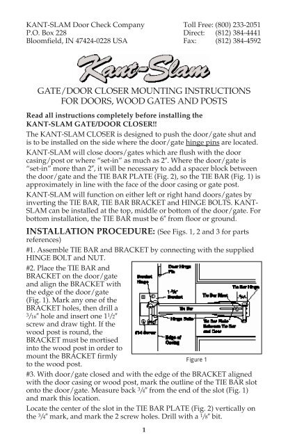
#1. Assemble TIE BAR and BRACKET by connecting with the supplied<br />
HINGE BOLT and NUT.<br />
#2. Place the TIE BAR and<br />
BRACKET on the <strong>door</strong>/<strong>gate</strong><br />
and align the BRACKET with<br />
the edge of the <strong>door</strong>/<strong>gate</strong><br />
(Fig. 1). Mark any one of the<br />
BRACKET holes, then drill a<br />
3/16 hole and insert one 1 1 /2<br />
screw and draw tight. If the<br />
<strong>wood</strong> post is round, the<br />
BRACKET must be mortised<br />
into the <strong>wood</strong> post in order to<br />
mount the BRACKET firmly<br />
Figure 1<br />
to the <strong>wood</strong> post.<br />
#3. With <strong>door</strong>/<strong>gate</strong> closed and with the edge of the BRACKET aligned<br />
with the <strong>door</strong> casing or <strong>wood</strong> post, mark the outline of the TIE BAR slot<br />
onto the <strong>door</strong>/<strong>gate</strong>. Measure back 3 /4 from the end of the slot (Fig. 1)<br />
and mark this location.<br />
Locate the center of the slot in the TIE BAR PLATE (Fig. 2) vertically on<br />
the 3 /4 mark, and mark the 2 screw holes. Drill with a 1 /8 bit.<br />
1
Insert the rivet (A) into the<br />
vertical slot in the TIE BAR<br />
PLATE (B) from the “U” side<br />
and attach the TIE BAR<br />
PLATE to the <strong>door</strong>/<strong>gate</strong> with<br />
the 2 screws (C). Insert the<br />
fiber washer (D) onto the<br />
rivet, move the TIE BAR to<br />
the TIE BAR PLATE, aligning<br />
the slot in the TIE BAR so the<br />
rivet projects through this<br />
slot, insert the steel washer<br />
(E) on the rivet, position<br />
the rivet hole horizontally<br />
Figure 2<br />
and install the cotter pin (F) through the hole in the rivet. The 3 /16<br />
movement between the connection of the TIE BAR and the TIE BAR<br />
PLATE ASSEMBLY is necessary <strong>for</strong> proper operation.<br />
#4. Open and close the <strong>door</strong>/<strong>gate</strong> to see that the TIE BAR works freely<br />
and its movement does not <strong>for</strong>ce the BRACKET to change position.<br />
Install the 3 remaining 1 1 /2 screws in the BRACKET.<br />
#5. Position the CYLINDER-SPRING ASSEMBLY (Fig. 3) so the<br />
ADJUSTING SCREW is pointed upward and the FILLER SCREW is<br />
toward you; insert the “S” LEVER HINGE into the BRACKET HINGE<br />
and connect the two with the HINGE BOLT, secure with the NUT. Move<br />
the CYLINDER-SPRING ASSEMBLY to the TIE BAR HINGE and<br />
connect with the HINGE BOLT by slightly opening the <strong>door</strong>/<strong>gate</strong> to<br />
attain the proper hinge alignment—then secure with the NUT.<br />
#6. Half open the <strong>door</strong>/<strong>gate</strong> and remove the “U” key from around the<br />
PISTON ROD. Save this “U” key as it must be replaced should it ever be<br />
necessary to remove the CYLINDER-SPRING ASSEMBLY. Open the<br />
<strong>door</strong>/<strong>gate</strong> 90° and allow the KANT-SLAM CLOSER to return the<br />
<strong>door</strong>/<strong>gate</strong> to the closed position. You may adjust the return speed of the<br />
<strong>door</strong>/<strong>gate</strong> by turning the ADJUSTING SCREW (Fig. 3) clockwise to slow<br />
the return or counterclockwise to increase the closing speed. Clip the<br />
COVER onto the CYLINDER<br />
with the curved section of the<br />
COVER up. Your installation<br />
is now complete.<br />
The KANT-SLAM unit is<br />
self-closing. To have the<br />
<strong>door</strong>/<strong>gate</strong> operate with a<br />
“stand open” mode, simply<br />
remove the Stop Nut shown<br />
in Figure 3. Removal of the<br />
Stop Nut will allow the <strong>door</strong>/<br />
<strong>gate</strong> to open beyond 90° and<br />
remain open until pushed<br />
Figure 3<br />
towards the closed position.<br />
2
Do not attempt to <strong>for</strong>ce the KANT-SLAM CLOSER beyond the Stop Nut.<br />
Doing so may damage the unit and keep it from operating properly.<br />
MOUNTING INSTRUCTIONS FOR METAL GATES<br />
INCLUDING CHAIN LINK GATES<br />
Read all <strong>instructions</strong> completely be<strong>for</strong>e installing the KANT-SLAM<br />
CLOSER.<br />
As there are several different types of <strong>gate</strong>s—ornamental iron, chain link,<br />
et al.,—these <strong>instructions</strong> will be basic, and an installer may need to<br />
adapt them. The <strong>mounting</strong> <strong>instructions</strong> <strong>for</strong> <strong>door</strong>s, <strong>gate</strong>s and posts<br />
generally apply, with the following exceptions.<br />
See Figures 1, 2 and 3 <strong>for</strong> parts references.<br />
#1. METAL POST INSTALLATION—TIE BAR BRACKET (Fig. 1). There<br />
are several methods of installation:<br />
A. The TIE BAR BRACKET may be welded to the metal post. Care<br />
must be taken to position the TIE BAR BRACKET according to<br />
<strong>instructions</strong> <strong>for</strong> <strong>door</strong>s, <strong>gate</strong>s and posts.<br />
B. A flat metal plate may be welded to the metal post. The TIE BAR<br />
BRACKET may then be bolted to the metal plate. (Metal plate<br />
and bolts are not included.)<br />
C. If the metal post has a flat surface at the desired <strong>mounting</strong><br />
location, the TIE BAR BRACKET may be bolted direct to the<br />
metal post.<br />
#2. CHAIN LINK GATES—INSTALLATION OF THE TIE BAR PLATE:<br />
For CHAIN LINK GATES,<br />
it may be necessary to<br />
secure a flat section of<br />
metal strip (approximately<br />
1/8 x 2) horizontally<br />
from one edge of the<br />
wire mesh to the other.<br />
This metal strip should<br />
be bolted or welded to<br />
the vertical wire mesh<br />
supports; this will secure<br />
the 2 metal strip to the<br />
chain link <strong>gate</strong>. The TIE<br />
BAR PLATE can be<br />
bolted to the 2 metal<br />
strip following the steps<br />
outlined in the <strong>mounting</strong><br />
<strong>instructions</strong> <strong>for</strong> <strong>door</strong>s,<br />
<strong>gate</strong>s and posts. (See<br />
Fig. 4) (2 metal strip<br />
not included.)<br />
Figure 4<br />
3
LIMITED WARRANTY<br />
KANT-SLAM DOOR CHECK COMPANY warrants the KANT-SLAM CLOSER <strong>for</strong><br />
12 months from date of purchase, only to the original purchaser, against defective<br />
material and workmanship. KANT-SLAM’S obligation under this warranty is<br />
limited to the repair or replacement, at its option, of the product or any parts<br />
thereof, when KANT-SLAM determines in good faith that the defect is due solely to<br />
materials and/or workmanship, and is conditioned upon payment by the purchaser<br />
of all transportation cost incident to such repair or replacement. Return the product<br />
or parts thereof, transportation prepaid, with proof of purchase date, to Factory<br />
Service Department, KANT-SLAM DOOR CHECK COMPANY, 46 W. Spring Street,<br />
Bloomfield, Indiana 47424. KANT-SLAM DOOR CHECK COMPANY reserves the<br />
right to levy a service charge <strong>for</strong> handling, packaging and refinishing the product or<br />
parts thereof. This warranty does not include the cost of any inconvenience or<br />
property damage due to the failure of the product, transportation damage, misuse,<br />
abuse, accident or similar incidents. This warranty gives you specific legal rights<br />
and you may also have other rights which vary from state to state. This warranty<br />
replaces all previous warranties and is the only warranty made by KANT-SLAM<br />
DOOR CHECK COMPANY on this product. No other warranties, either verbal or<br />
written, are authorized.<br />
THE KANT-SLAM DOOR CHECK CO.<br />
Drawer 228 • Bloomfield, Indiana 47424<br />
IMPORTANT<br />
Dealer: Please bring this Envelope to Attention of Purchaser.<br />
BEFORE INSTALLING KANT-SLAM<br />
READ INSTRUCTIONS CAREFULLY.<br />
KEEP THESE INSTRUCTIONS<br />
FOR FURTHER REFERENCE.<br />
SERVICE INFORMATION<br />
The brass PACKING NUT on top of the CYLINDER SHOULD NEVER BE<br />
LOOSENED! If a slight amount of fluid appears to be leaking around the PISTON<br />
ROD, the PACKING NUT should be tightened 1/8 of a full turn but NEVER MORE<br />
THAN 3 TURNS!<br />
If completely tightening the ADJUSTING SCREW clockwise does not adequately<br />
restrict the closing speed of the (<strong>door</strong>-<strong>gate</strong>), the CYLINDER is low on fluid. To<br />
replace fluid, put Universal Hydraulic Fluid in a squirt type can, close the (<strong>door</strong><strong>gate</strong>),<br />
remove the FILLER SCREW, insert the spout of the can into the FILLER<br />
SCREW HOLE, fill the CYLINDER completely with fluid . . . replace the FILLER<br />
SCREW tightly.<br />
Printed in U.S.A.<br />
4