Shure SM81 | PDF - SRTalumni.com
Shure SM81 | PDF - SRTalumni.com
Shure SM81 | PDF - SRTalumni.com

You also want an ePaper? Increase the reach of your titles
YUMPU automatically turns print PDFs into web optimized ePapers that Google loves.
Model <strong>SM81</strong> User Guide<br />
SPECIFICATIONS<br />
Type<br />
Condenser (electret bias)<br />
Frequency Response<br />
20 to 20,000 Hz<br />
+20<br />
+10<br />
MODEL <strong>SM81</strong> UNIDIRECTIONAL<br />
CONDENSER MICROPHONE<br />
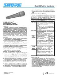
The <strong>Shure</strong> Model <strong>SM81</strong> is a high-quality, unidirectional condenser<br />
microphone designed for studio recording, broadcasting,<br />
and sound reinforcement. Its wide frequency response, low noise<br />
characteristics, and low RF susceptibility have made it a standard<br />
for applications involving acoustic instruments, especially guitar,<br />
piano, and cymbals.<br />
The <strong>SM81</strong> is ruggedly constructed. It operates on phantom power<br />
and performs over a wide range of temperatures and humidity<br />
conditions. It is furnished with a swivel adapter, attenuator-switch<br />
lock, foam windscreen, and case for carrying and storage. Other<br />
accessories are available.<br />
Model <strong>SM81</strong> Features<br />
• 20 Hz to 20 kHz frequency response<br />
• Flat response curve for accurate reproduction of sound<br />
sources<br />
• Low noise and high output clipping level<br />
• Low distortion over a wide range of load impedances<br />
• Cardioid polar pattern, uniform with frequency and symmetric<br />
about axis, providing maximum rejection and minimum<br />
coloration of off-axis sounds<br />
• Low RF susceptibility<br />
• Selectable low-frequency response: flat, 6 or 18 dB/octave<br />
rolloff<br />
• 0 dB/10 dB lockable attenuator switch<br />
• Phantom powering (DIN 45 596 voltages of 12 to 48 Vdc)<br />
• Rugged steel construction for durability<br />
• Field-usable over wide range of temperature and humidity<br />
conditions<br />
dB<br />
0<br />
–10<br />
-20<br />
2 3 4 5 6 789 2 3 4 5 6 789<br />
20 50 100<br />
1000 10000 20000<br />
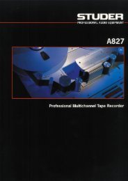
TYPICAL FREQUENCY RESPONSE<br />
FIGURE 1<br />
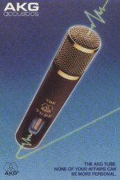
Polar Pattern<br />
Cardioid (unidirectional) response-uniform with frequency, symmetrical<br />
about axis<br />
90°<br />
120°<br />
60°<br />
150°<br />
30°<br />
180°<br />
–20 dB<br />
–15 dB<br />
–10 dB<br />
–5 dB<br />
0<br />
1000 Hz<br />
500 Hz<br />
100 Hz<br />
150°<br />
30°<br />
120°<br />
60°<br />
90°<br />
TYPICAL POLAR PATTERNS<br />
FIGURE 2<br />
Output Impedance<br />
Rated at 150 Ω (85 Ω actual)<br />
Re<strong>com</strong>mended minimum load impedance: 800 Ω (May be used<br />
with loads as low as 150 Ω with reduced clipping level)<br />
Output Configuration and Connector<br />
Balanced, transformer-coupled output; male XLR connector<br />
Sensitivity (at 1,000 Hz)<br />
Open Circuit Voltage: . . . . . . . . . . . .–45 dBV/Pascal (5.6 mV)<br />
(1 Pascal = 94 dB SPL)<br />
Clipping Level (at 1,000 Hz)<br />
800 Ω Load: . . . . . . . . . . . . . . . . . . . . . . . . . . –4 dBV (0.63 V)<br />
150 Ω Load: . . . . . . . . . . . . . . . . . . . . . . . . . –15 dBV (0.18 V)<br />
Total Harmonic Distortion<br />
Less than 0.5% (131 dB SPL at 250 Hz into 800 Ω load)<br />
Hz<br />
90°<br />
120°<br />
60°<br />
1 METER<br />
150°<br />
30°<br />
180°<br />
–20 dB<br />
–15 dB<br />
–10 dB<br />
–5 dB<br />
0<br />
150°<br />
30°<br />
2000 Hz<br />
5000 Hz<br />
10000 Hz<br />
120°<br />
60°<br />
90°<br />
©2005, <strong>Shure</strong> Incorporated<br />
27C2916 (Rev. 6)<br />
Printed in U.S.A.
Maximum SPL (at 1,000 Hz)<br />
800 Ω load: . . . . . . . . . . . . . . . . . . . . . 136 dB (attenuator at 0)<br />
146 dB (attenuator at -10)<br />
150 Ω load: . . . . . . . . . . . . . . . . . . . . . 128 dB (attenuator at 0)<br />
138 dB (attenuator at -10)<br />
Hum Pickup<br />
-3 dB equivalent SPL in a 1 mOe field (60 Hz)<br />
Self-Noise (equivalent sound pressure levels; measured with true<br />
rms voltmeter)<br />
16 dB typical, A-weighted<br />
19 dB typical, weighted per DIN 45 405<br />
Signal-to-Noise Ratio<br />
78 dB (IEC 651)* at 94 dB SPL<br />
*S/N ratio is difference between microphone output at 94 dB SPL and<br />
microphone self-noise A-weighted.<br />
Overvoltage and Reverse Polarity Protection<br />
Max. external voltage applied to pins 2 and 3<br />
with respect to pin 1: . . . . . . . . . . . . . . . . . . . . . . . . . +52 Vdc<br />
Reverse polarity protection: . . . . . . . . . . . . . . . . 200 mA max.<br />
(diode-clamped)<br />
Polarity<br />
Positive pressure on diaphragm produces positive voltage on<br />
pin 2 relative to pin 3<br />
Cartridge Capacitance<br />
54 pF<br />
Low Frequency Response Switch Positions<br />
Flat; -6 dB/octave below 100 Hz; -18 dB/octave below 80 Hz<br />
Attenuator Switch Positions (Lockable)<br />
0 or -10 dB<br />
Power<br />
Supply Voltage:. . . . . . . . . 11 to 52 Vdc, positive, pins 2 and 3<br />
Current Drain: . . . . . . . . . . . . . . . . . . . . . . . . . . . . 1.2 mA max.<br />
Environmental Conditions<br />
Temperature<br />
Storage: . . . . . . . . . . . . . . . . . . . . . . . . . . . . . –29° to 74° C<br />
(–20° to 165° F)<br />
Operating:. . . . . . . . . . . . . . . . . . . . . . . . . . . . –6.7° to 49° C<br />
(20° to 120° F)<br />
Humidity<br />
Storage: . . . . . . . . . . . . . . 0–95% relative humidity at room<br />
temperature (72° to 80° F, 22° to 27° C)<br />
Case<br />
Steel construction with vinyl metallic paint finish and stainless<br />
steel screens<br />
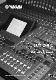
Dimensions<br />
See Figure 3<br />
Weight<br />
Net: . . . . . . . . . . . . . . . . . . . . . . . . . . . . . . . . 230 grams (8 oz)<br />
Packaged: . . . . . . . . . . . . . . . . . . . . . . . 740 grams (1 lb 10 oz)<br />
Certification<br />
Eligible to bear CE marking. Conforms to European EMC Directive<br />
89/336/EEC. Meets applicable tests and performance criteria<br />
in European EMC Standard EN 55103 (1996) parts 1 and<br />
2 for residential (E1) and light industrial (E2) environments.<br />
OPERATION<br />
Power<br />
The <strong>SM81</strong> requires phantom power. This may be supplied to the<br />
microphone by a mixer, preamplifier or console with built-in phantom<br />
power or from an external power supply (such as the <strong>Shure</strong><br />
model PS1A). Phantom power sources providing between 11 and<br />
52 Vdc are suitable.<br />
Use only high-quality cables because intermittent shorts between<br />
broken shield wires and balanced conductors will cause extremely<br />
large noise transients in the system. Avoid ground loops<br />
due to grounded connector shells or the microphone case touching<br />
other grounded metal objects. Follow generally accepted audio<br />
grounding practices.<br />
Impedance<br />
A minimum load impedance of 800 Ω or greater should be used<br />
for maximum signal handling and minimum distortion. The load<br />
may be as low as 150 Ω, but a reduction in output clipping level will<br />
result. It should be noted that the power supply itself may add loading<br />
(3300 Ω in the <strong>Shure</strong> PS1A power supply) to the microphones.<br />
PS1A Power Supply<br />
When using the <strong>Shure</strong> PS1A to phantom power the <strong>SM81</strong>, connect<br />
the microphone cable to the <strong>SM81</strong> and to the MICROPHONE<br />
connector of the power supply. The power supply uses the balanced<br />
audio cable pair to carry the supply current to the microphone<br />
and the cable shield as a ground return.<br />
Connect the OUTPUT connector of the power supply to a<br />
low-impedance microphone input of a mixer, audio console or tape<br />
recorder. A second <strong>SM81</strong> may be connected to the remaining power<br />
supply channel in a similar manner.<br />
212 mm<br />
23.5 mm<br />
20 mm<br />
OVERALL DIMENSIONS<br />
FIGURE 3<br />
2
Low-Frequency Response Filter<br />
The <strong>SM81</strong> has a three-position low-frequency response filter<br />
controlled by a switch located on its handle. The switch is recessed<br />
to avoid accidental movement, but may be easily moved with fingertips.<br />
The user may select either flat response, low-frequency<br />
rolloff of 6 dB per octave below 100 Hz, or low-frequency cutoff of<br />
18 dB per octave below 80 Hz (see Figure 4). When close-miking<br />
instruments or vocalists, an increase in low-frequency response<br />
(proximity effect) takes place. Figure 4 illustrates this effect with the<br />
switch in each of the three positions. Note that the low-frequency<br />
response filter may be used to <strong>com</strong>pensate for proximity effect or<br />
reduce low-frequency noise from stage traffic and other sources.<br />
+10<br />
152.4 MM ( )<br />
require attenuation (or padding). If no attenuation is available on<br />
the preamplifier, mixer or console being used, a resistive attenuator<br />
can be inserted between the microphone and the input. The<br />
<strong>Shure</strong> Model A15AS Attenuator (15, 20, or 25 dB switch-selectable)<br />
is specially designed for use with condenser microphones<br />
such as the <strong>SM81</strong>. Alternately, the attenuator design shown in Figure<br />
5 may be used. The resistors shown are 1/2-watt, 1% tolerance,<br />
and the circuit may be packaged in a Switchcraft S3FM<br />
adapter housing. The circuit will provide15 dB of attenuation and<br />
can be used between the <strong>SM81</strong> and the PS1A (or other power supply),<br />
or between the PS1A and the mixer. Two of these circuits may<br />
be used in series to provide 30 dB of attenuation. (Note that, due<br />
to excessive loading, <strong>com</strong>mercially available 150 Ω attenuators,<br />
such as the <strong>Shure</strong> Model A15AS, are not re<strong>com</strong>mended when two<br />
are used in series.)<br />
dB<br />
–10<br />
0<br />
152.4 MM ( )<br />
INPUT FROM<br />
MICROPHONE<br />
152.4 MM ( ) 1 2<br />
3<br />
412<br />
OUTPUT TO<br />
MIXER<br />
2 1<br />
3<br />
PROXIMITY EFFECT AND COMPENSATION<br />
FIGURE 4<br />
Attenuator Switch<br />
The <strong>SM81</strong> has a switchable 10 dB capacitive attenuator to prevent<br />
high sound pressure levels from overloading its internal electronics.<br />
The attenuator is engaged by rotating the actuator ring,<br />
located directly below the grille assembly, until it reaches the “-10"<br />
position. This reduces the output of the microphone by 10 dB and<br />
increases the maximum sound pressure level at clipping by 10 dB.<br />
There are no intermediate levels of attenuation available.<br />
The attenuator ring may be locked in either the “0" or “-10" position<br />
as follows. Unscrew the grille and cartridge assembly by unscrewing<br />
counter-clockwise from the top. Turn the actuator ring to<br />
the “0" or “-10" position as desired. Insert the actuator ring lock<br />
(small clear piece of plastic) in the area behind the actuator ring between<br />
the pin and the edge of the slot. This will prevent the ring<br />
from turning. Replace the grill and cartridge assembly.<br />
Mixer Overload<br />
20 50 100<br />
1000<br />
The <strong>SM81</strong>'s output is about 15 dB higher than most dynamic microphones.<br />
At moderate to high SPLs, this additional output may<br />
Hz<br />
Wind Noise<br />
412<br />
15 DB ATTENUATOR CIRCUIT<br />
FIGURE 5<br />
The wide frequency response of the <strong>SM81</strong> makes it sensitive to<br />
wind, breath, and air currents from heating, ventilation and cooling<br />
(HVAC) systems. The foam windscreen included with the <strong>SM81</strong><br />
can be used to reduce wind and breath noise, while the low-frequency<br />
response filter can be used to reduce low-frequency room<br />
noise caused by HVAC systems.<br />
The Model A81G Pop Filter Grille attenuates breath popping<br />
sounds when the microphone is close-talked, and permits its use<br />
outdoors with minimal pickup of rushing and rumbling sounds. To<br />
install the A81G, slip it over the <strong>SM81</strong> until the inside of the A81G<br />
touches the top of the microphone. Tighten the A81G by rotating<br />
the knurled collar clockwise from the bottom. (Note: When removing<br />
the A81G, first loosen the knurled collar. Otherwise the cartridge<br />
will unscrew with the A81G.)<br />
For outdoor use under very windy conditions, use the Model<br />
A81WS large foam windscreen.<br />
215<br />
3
CAPACITOR<br />
CARTRIDGE<br />
BALANCED<br />
TRANSFORMER<br />
FET IMPEDANCE<br />
CONVERTER<br />
LF RESPONSE<br />
FILTER<br />
CLASS A<br />
COMPOUND<br />
AMPLIFIER<br />
RFI<br />
FILTER<br />
CAPACITIVE<br />
ATTENUATOR<br />
REGULATOR/<br />
REVERSE<br />
VOLTAGE<br />
PROTECT<br />
BLOCK DIAGRAM<br />
FIGURE 6<br />
CIRCUIT DESCRIPTION<br />
A block diagram of the <strong>SM81</strong> is shown in Figure 6. The capacitor<br />
cartridge is followed by a switch-controlled capacitive attenuator<br />
stage which provides for 10 dB attenuation at the cartridge output.<br />
The signal is fed to a field-effect transistor (FET) impedance conversion<br />
stage. The FET output drives an active low-frequency response<br />
(high-pass) filter controlled by a three-position switch. The<br />
filter output from a <strong>com</strong>pound transistor, Class A, emitter-follower<br />
amplifier is transformer-coupled, providing a balanced output to<br />
the RFI protection filter at the microphone connector. An active,<br />
constant-current power supply circuit regulates the phantom voltage,<br />
allowing the <strong>SM81</strong> to operate over a very wide range of voltages.<br />
A reverse voltage protection diode guards against miswired<br />
cables and equipment.<br />
TROUBLESHOOTING<br />
If the <strong>SM81</strong> fails to operate properly, verify that the microphone<br />
is powered properly.<br />
1. Check the power supply output voltage to the microphone. For<br />
the <strong>Shure</strong> PS1A, this should be 21.5 + 1.5 Vdc open circuit.<br />
2. Check the voltage on microphone connector pins 2 and 3 (at<br />
back of connector; cable connector disassembled from shell<br />
but connected to microphone). The voltage at pins 2 and 3<br />
with reference to pin 1 should be between 11 and 52 Vdc.<br />
Due to its high packing density and circuit <strong>com</strong>plexity, disassembly<br />
of the <strong>SM81</strong> is not re<strong>com</strong>mended. Contact <strong>Shure</strong>'s Service Department<br />
if problems persist.<br />
ARCHITECTS' SPECIFICATION<br />
The microphone shall be a condenser microphone with a frequency<br />
response of 20 to 20,000 Hz. It shall have a unidirectional<br />
pickup characteristic, with cancellation at the sides of 6 dB and a<br />
minimum cancellation at the rear of 15 dB at 1 kHz. The microphone<br />
shall have a rated output impedance of 150 Ω for connection<br />
to microphone inputs of 150 ohms or higher. The open circuit<br />
voltage shall be -65 dB (0.56 mV) (0 dB equals 1 volt per microbar).<br />
The microphone shall contain a three-position low-freq-uency<br />
response switch and a lockable 10 dB attenuator pad.<br />
The overall dimensions shall be 212 mm (8-11/32 in.) in length<br />
by 23.5 mm (15/16 in.) in diameter. The handle diameter shall be<br />
20.1 mm (25/32 in.). The weight shall be 230 grams (8oz).<br />
The microphone shall be capable of being powered by a phantom<br />
power supply with an output of 11 to 52 Vdc, or by a mixer, audio<br />
console or tape recorder capable of supplying 11 to 52 Vdc.<br />
The microphone shall be a <strong>Shure</strong> Model <strong>SM81</strong>.<br />
FURNISHED ACCESSORIES<br />
Swivel Adapter........................................................A57F<br />
10 dB Attenuator Lock ....................................... 34A830<br />
Carrying/Storage Case ..................................... 65A1797<br />
Windscreen..........................................................49A111<br />
OPTIONAL ACCESSORIES<br />
Pop-Filter Grille...................................................... A81G<br />
Heavy-Duty Windscreen ..................................... A81WS<br />
Tripod Microphone Stand (4.3 m [14 ft])..................S15A<br />
Stereo Microphone Adapter ................................... A27M<br />
Cable (7.6m [25ft]) ..................................................C25F<br />
Phantom Power Supply ......................................... PS1A<br />
REPLACEMENT PARTS<br />
Cartridge and Grille Assembly ............................... R104<br />
4