AD-16X User's Guide - Apogee
AD-16X User's Guide - Apogee
AD-16X User's Guide - Apogee

You also want an ePaper? Increase the reach of your titles
YUMPU automatically turns print PDFs into web optimized ePapers that Google loves.
16-channel24 bit, 192 kHz, A/D ConverterUser’s <strong>Guide</strong>v2.0 - January 2005
16-channel24 bit, 192 kHz, A/D ConverterUser’s <strong>Guide</strong>v2.0 - January 2005
<strong>AD</strong>-<strong>16X</strong> – User’s <strong>Guide</strong>APOGEE ELECTRONICSWarningsFCC warningThis equipment has been tested and found to comply with the limits for a Class A digital device, pursuantto Part 15 of the FCC rules. These limits are designed to provide reasonable protection againstharmful interference when operated in a commercial environment. This equipment generates, uses,and can radiate radio frequency energy and, if not installed and used in accordance with the instructionmanual, may cause harmful interference to radio communications. Operation of this equipment ina residential area is likely to cause harmful interference, in which case the user will be required to takewhatever measures necessary to correct the interference at his own expense.Copyright NoticeThe <strong>Apogee</strong> <strong>AD</strong>-<strong>16X</strong> is a computer-based device, and as such contains and uses software in ROMs.This software, and all related documentation, including this User’s <strong>Guide</strong> contain proprietary informationwhich is protected by copyright laws. All rights are reserved. No part of the software and its relateddocumentation may be copied, transferred, or modified. You may not modify, adapt, translate, lease,distribute, resell for profit or create derivative works based on the software and its related documentationor any part thereof without prior written consent from <strong>Apogee</strong> Electronics Corporation, U.S.A.ii
<strong>AD</strong>-<strong>16X</strong> – User’s <strong>Guide</strong>APOGEE ELECTRONICSRegistration and Warranty InformationBe sure to register your <strong>AD</strong>-<strong>16X</strong>, either by filling in the enclosed Registration Card or by completingthe on-line registration form at our Web site: http://www.apogeedigital.com/support/. If you do so,<strong>Apogee</strong> can contact you with any update information. As enhancements and upgrades are developed,you will be contacted at the registration address. Firmware updates are free for the first year ofownership unless otherwise stated. Please address any inquiries to your dealer or directly to <strong>Apogee</strong>at:APOGEE ELECTRONICS CORPORATION,3145 Donald Douglas Loop South, Santa Monica, CA 90405, USA.TEL: (310) 915-1000, FAX: (310) 391-6262email: support@apogeedigital.com. Web: http://www.apogeedigital.com/APOGEE ELECTRONICS CORPORATION warrants this product to be free of defects in material andmanufacture under normal use for a period of 12 months. The term of this warranty begins on thedate of sale to the purchaser. Units returned for warranty repair to <strong>Apogee</strong> or an authorized <strong>Apogee</strong>warranty repair facility will be repaired or replaced at the manufacturer’s option, free of charge.ALL UNITS RETURNED TO APOGEE OR AN AUTHORIZED APOGEE REPAIR FACILITY MUSTBE PREPAID, INSURED AND PROPERLY PACKAGED, PREFERABLY IN THEIR ORIGINAL BOX.<strong>Apogee</strong> reserves the right to change or improve design at any time without prior notification. Designchanges are not implemented retroactively, and the incorporation of design changes into future unitsdoes not imply the availability of an upgrade to existing units.This warranty is void if <strong>Apogee</strong> determines, in its sole business judgment, the defect to be the resultof abuse, neglect, alteration or attempted repair by unauthorized personnel.The warranties set forth above are in lieu of all other warranties, expressed or implied, and <strong>Apogee</strong>specifically disclaims any and all implied warranty of merchantability or of fitness for a particularpurpose. The buyer acknowledges and agrees that in no event shall the company be held liable forany special, indirect, incidental or consequential damages, or for injury, loss or damage sustained byany person or property, that may result from this product failing to operate correctly at any time.USA: Some states do not allow for the exclusion or limitation of implied warranties or liability forincidental or consequential damage, so the above exclusion may not apply to you. This warrantygives you specific legal rights, and you may have other rights which vary from state to state.Service InformationThe <strong>AD</strong>-<strong>16X</strong> contains no user-serviceable components: refer to qualified service personnel for repairor upgrade. Your warranty will be voided if you tamper with the internal components. If you have anyquestions with regard to the above, please contact <strong>Apogee</strong>.In the event your <strong>AD</strong>-<strong>16X</strong> needs to be upgraded or repaired, it is necessary to contact <strong>Apogee</strong> priorto shipping, and a Return Materials Authorization (RMA) number will be assigned. This number willserve as a reference for you and helps facilitate and expedite the return process. <strong>Apogee</strong> requiresthat shipments be pre-paid and insured — unless otherwise authorized in advance.IMPORTANT: ANY SHIPMENT THAT IS NOT PRE-PAID OR IS SENT WITHOUT AN RMANUMBER WILL NOT BE ACCEPTED.iii
<strong>AD</strong>-<strong>16X</strong> – User’s <strong>Guide</strong>APOGEE ELECTRONICSDeclarations of ConformityDeclaration of Conformity—FCC<strong>Apogee</strong> <strong>AD</strong>-<strong>16X</strong>This device complies with Part 15 of the FCC Rules. Operation is subject to the following two conditions:(1) This device may not cause harmful interference(2) This device must accept any interference received, including interference that may cause undesired operation.This equipment has been tested and found to comply with the limits of a Class B digital device, pursuant to Part15 of the FCC Rules. These limits are designed to provide reasonable protection against harmful inteference in aresidential installation. This equipment generates, uses and can radiate radio frequency energy and, if not installedand used in accordance with the instructions, may cause harmful interference to radio communications. If thisequipment does cause harmful interference to radio or television reception, which can be determined by turningthe equipment off and on, the user is encouraged to try to correct the interference by one or more of the followingmeasures:1. Re-orient or relocate the receiving antenna.2. Increase the separation between the equipment and receiver.3. Connect the equipment into an outlet on a different circuit from that to which the receiver is connected.4. Consult the dealer or an experienced radio/TV technician for help.NOTE: The use of non-shielded cable with this equipment is prohibited.CAUTION: Changes or modifications not expressly approved by the manufacturer responsible for compliancecould void the user’s authority to operate the equipment.<strong>Apogee</strong> Electronics Corporation, 3145 Donald Douglas Loop South, Santa Monica, CA 90405.Betty Bennett, CEO.Industry Canada NoticeThis Class B digital apparatus meets all requirements of the Canadian Interference-Causing Equipment Regulations.Cet appareil numérique de la classe B respecte toutes les exigences du Règlement sur le matérial brouilleurdu Canada.Declaration of Conformity – CE<strong>Apogee</strong> Electronics Corporation hereby declares that the product, the <strong>AD</strong>-<strong>16X</strong>, to which this declaration relates, isin material conformity with the following standards or other normative documents:• EN50081-1/EN55022; 1995• EN50082-1/IEC 801-2, 3, 4; 1992following the provisions of:• 73/23/EEC – Low Voltage Directive• 89/336/EEC – EMC DirectiveDeclaration of Conformity – Japan<strong>Apogee</strong> Electronics Corporation hereby declares that the <strong>AD</strong>-<strong>16X</strong>, to which this declaration relates, is in materialconformity with the VCCI Class A standard.Declaration of Conformity – Australia<strong>Apogee</strong> Electronics Corporation hereby declares that the <strong>AD</strong>-<strong>16X</strong> is in material conformity with AN/NZS standardrequirements.iv
User’s <strong>Guide</strong>Table of ContentsIntroduction ....................................................................................................................2Signal Flow Diagram ....................................................................................................2Getting Started Quickly...............................................................................................3Installation ..............................................................................................................3Connecting Power ..................................................................................................3Reset .....................................................................................................................3QuickStart ..............................................................................................................3Signal Flow .............................................................................................................3Navigating the Front Panel ....................................................................................4-7Power Switch..........................................................................................................4Setup buttons .........................................................................................................4Primary Parameter Loop ........................................................................................4CLOCK SOURCE...................................................................................................5SAMPLE RATE ......................................................................................................5WC Ratio ................................................................................................................5Lock indication ........................................................................................................5CAL mode indicator ................................................................................................6UV22HR .................................................................................................................6SoftLimit .................................................................................................................7AES format .............................................................................................................7CLEAR ...................................................................................................................7Level Meters ...........................................................................................................7Standard and Advanced Option Routing .........................................................8-10Overview ................................................................................................................8Advanced Option Routing Example: Additional Digital I/O.....................................9Advanced Option Routing Example: Expanded Interface Choices ......................10Connections on the Rear Panel ..............................................................................11OUT 1-8 ................................................................................................................11OUT 9-16 ..............................................................................................................11OPTION ................................................................................................................11<strong>AD</strong>AT – S/MUX .....................................................................................................11AES IN ..................................................................................................................11WC IN ...................................................................................................................11WC OUT................................................................................................................11WC IN Termination Switch .....................................................................................11Internal Adjustments.............................................................................................12-13MIDI Firmware update connector ...........................................................................12Power switch calibration.......................................................................................13
<strong>AD</strong>-<strong>16X</strong> – User’s <strong>Guide</strong>APOGEE ELECTRONICSIntroductionThe <strong>AD</strong>-<strong>16X</strong>, <strong>Apogee</strong>’s latest and most advanced analog to digital converter, takes the legendary quality of<strong>Apogee</strong> a significant step forward. Features such as a redesigned power supply, standard 192kHz sampling rates,the C777 clocking technology found in Big Ben, and optional Pro Tools HD and FireWire expansion cards, makethe <strong>AD</strong>-<strong>16X</strong> the most powerful and flexible A-to-D converter ever.Advanced High-Definition ConversionWith up to 192k standard sample rates, the <strong>AD</strong>-<strong>16X</strong> combines <strong>Apogee</strong>’s legendary conversion quality withthe very latest in high-definition digital to provide unrivaled flexibility and quality.C777 Clocking used by Big BenThe <strong>AD</strong>-<strong>16X</strong> uses <strong>Apogee</strong>’s C777 clocking technology. Famous for keeping Big Ben on time, the C777utilizes an entirely digital process that <strong>Apogee</strong> has developed with the most advanced Direct DigitalSynthesis (DDS) technology and DSP-based digital filtering. With a stable, crystal based digital PLLhandling the clocking, the <strong>AD</strong>-<strong>16X</strong> is able to intelligently manipulate incoming signals and adapt to themaccordingly, resulting in unprecedented jitter attenuation and an astonishing and noticeable difference insound quality.Advanced Option RoutingWith version 2 firmware, both digital inputs and analog outputs may be routed in conjunction with aninstalled X-Option card. Please see page 7 for details.Universal ConnectivityWith it’s wide array of standard and optional digital outputs, the <strong>AD</strong>-<strong>16X</strong> can be connected to virtually anydigital system. The <strong>AD</strong>-<strong>16X</strong> includes AES and <strong>AD</strong>AT Optical digital outputs as standard, while either theX-HD or X-FireWire cards may be installed for connectivity to Pro Tools HD or any FireWire equippedcomputer.SoftLimitSoft Limit is an analog peak limiter that instantaneously and gracefully controls transient peaks,thereby allowing an additional 4-6 dB of headroom. Short of purchasing a very expensive stand-alonecompressor/limiter, there is currently no product on the market that handles this process better thanSoftLimit.UV22HRUV22HR is <strong>Apogee</strong>´s industry standard technology for reducing the word-length of a high-resolution digitalsignal to 16 bits. UV22HR is also being employed to produce dramatically improved internet and computeraudio content without increased file sizes or data rates. It is estimated that 8 out of 10 hit records aremastered using <strong>Apogee</strong>’s UV22HR technology.2
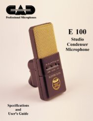
<strong>AD</strong>-<strong>16X</strong> – User’s <strong>Guide</strong>APOGEE ELECTRONICSNavigating the Front Panel1 21) Power Switch - The POWER switch may be configured to operate in the manner best suited to the installationof the unit; for example, if the <strong>AD</strong>-<strong>16X</strong> is installed in a rack with a Master power switch, the unit may beconfigured to power on when the Master switch is turned on. Please see the section of this manual entitled“Internal Adjustments” for details.Note that the POWER switch LED indicates that the <strong>AD</strong>-<strong>16X</strong> is receiving a proper AC input, and is inStandby. The LED goes out when the <strong>AD</strong>-<strong>16X</strong> is powered on.2) Setup buttons and LED - These buttons are used to modify all settings on the <strong>AD</strong>-<strong>16X</strong>. In general, settingmodification is accomplished by :a) enabling Setup mode by pressing any of the 4 buttons (the Setup LED will light and one parametervalue will flash);b) using the PREV or NEXT buttons to scroll to the parameter to be modified;c) using the UP or DOWN buttons to select the desired parameter value.PRIMARY PARAMETER LOOPClock Sample WCSoftAES GlobalP N P NP N P N UV22 P N P N P N P NSource Rate RatioLimit Format CALUV22 CHANNEL SELECT MODEPress and holdPREV or NEXTPress and holdPREV or NEXTPress and holdPREV or NEXTP NCH1-2P NCH3-4P NCH5-6etc...CH15-16P NSOFT LIMIT CHANNEL SELECT MODEP NCH1P NCH2P NCH3etc...CH16P NCHANNEL CAL MODEPREVP NNEXTP NCH1P NCH2P NCH3etc...CH16P NFigure 14
<strong>AD</strong>-<strong>16X</strong> – User’s <strong>Guide</strong>APOGEE ELECTRONICSNavigating the Front Panel - continued34 567After Setup mode is enabled, pressing the PREV or NEXT button will cycle through the <strong>AD</strong>-<strong>16X</strong>’s sevenparameters - CLOCK SOURCE, SAMPLE RATE, WC ratio, UV22HR, SOFT LIMIT, AES format and CALmode- and then return to the first parameter. Likewise, pressing the UP or DOWN buttons will cycle throughthe values available for the selected parameter. Once a value is selected, it immediately becomes active,regardless if the LED is flashing to indicate that Setup mode has been enabled.If either the UV22HR, SOFT LIMIT or CAL mode parameters has been selected, pressing and holding eitherthe PREV or NEXT button will allow the user to enter a corresponding Channel mode; it’s now possible tocycle through channels 1-16 in order to make settings to individual channels. Please see page 6 for moredetails concerning CAL modes. Figure 1 depicts the parameter cycles of the <strong>AD</strong>-<strong>16X</strong>.Parameters 3-7 are displayed in the Clock Window, as indicated at the top of this page.3) CLOCK SOURCE – This parameter determines the clock source of the <strong>AD</strong>-<strong>16X</strong>, and may be set to INTernal crystalor WC input.4) SAMPLE RATE - When the CLOCK SOURCE is set to INTernal , the Sample Rate display indicates the frequencyof the internally generated clock, and may be set to any standard sample rates from 44.1 to 192 kHz. When theCLOCK SOURCE is set to WC, the display indicates the sample rate of the <strong>AD</strong>-<strong>16X</strong> as a result of locking to theselected source; the sample rate cannot be set by the user.5) WC Ratio – This parameter determinesthe ratio between the word clockInput/Output frequency and the unit’ssample rate. Figure 2 indicates theresultant <strong>AD</strong>-<strong>16X</strong> sample rate given aspecific WC Frequency Ratio settingand word clock input frequency. Likewise,the word clock output frequencymay be determined given a specificWC Ratio setting and <strong>AD</strong>-<strong>16X</strong> samplerate. This parameter should be usedto adjust the <strong>AD</strong>-<strong>16X</strong> word clock I/O toFigure 2WC RatioSettingWord Clock I/O Frequency44.1kHz 48kHz 88.2kHz 96kHz 176.4kHz 192kHzWC x1: 44.1kHz 48kHz 88.2kHz 96kHz 176.4kHz 192kHzWC /2: 88.2kHz 96kHz 176.4kHz 192kHzWC/4: 176.4kHz 192kHzResultant <strong>AD</strong>-<strong>16X</strong> Sample Rateaccommodate the requirements of specific digital systems. For example, to configure the <strong>AD</strong>-<strong>16X</strong> to lock to a48kHz word clock input and run at a sample rate of 192kHz, set WC Ratio to WC fs/4.6) Lock indication – These LEDs indicate the Lock status of the <strong>AD</strong>-<strong>16X</strong>’s C777 clock. Two levels of lock precisionare displayed, Wide and Narrow. When the Narrow LED and “Lock Exclamation Point” are lit, the <strong>AD</strong>-<strong>16X</strong>has locked to the selected CLOCK SOURCE in such a way to ensure the highest quality A-to-D conversion. Ifthe Wide LED or only the upper section of the Lock Exclamation Point lights, the stability of the clock source isquestionable, and should be verified.“LockExclamationPoint”Thanks to SureLock, <strong>Apogee</strong>’s intelligent clock continuity algorithm, the <strong>AD</strong>-<strong>16X</strong> will output a stable clock signaleven if the selected CLOCK SOURCE is interrupted. When SureLock is engaged, the arrow section of the Lockexclamation point flashes to indicate a loss of the clock source, while the Narrow LED and blue point light solidly toindicate a stable clock output.5
<strong>AD</strong>-<strong>16X</strong> – User’s <strong>Guide</strong>APOGEE ELECTRONICSNavigating the Front Panel - continued877) CAL mode indicator – This LED indicates that either Global or Channel CALibration mode is enabled, and that theanalog to digital conversion level may be calibrated. Global CAL allows the calibration of all 16 channels simultaneously,while Channel CAL allows calibration of individual channels. Global CAL mode is enabled by scrolling throughthe 7 front panel parameters until the CAL LED flashes; “global Cal” will scroll across the Sample Rate display,followed by the digital output level of channel 1. Once enabled, all 16 analog input levels may be adjusted simultaineouslyby one of three operations:• Press and Hold UP to raise the analog input level and DOWN to lower the level.• Press and release UP or DOWN to modify the analog inputs +-.01 dB;• Quickly tap UP or DOWN twice (think of a double mouse click) to modify the analog inputs +- 1.0 dB.This double press function may be used to quickly jump from a “house” reference level to anotherreference level in precise 1 dB steps.Saving calibrationsettingsChannel CAL mode is enabled by scrolling through the 7 front panel parameters until the CAL LED flashes,then pressing and holding either the PREV or NEXT buttons until “ch 1” scrolls across the Sample Rate display.Keeping in mind that Setup mode is always enabled while in Channel CAL mode, channel 1’s analog output maybe modified by the same operations described on the previous page. To adjust channels 2-16, press either thePREV or NEXT button until the LED corresponding to the channel to be modified is lit.To exit Channel CAL mode, press and hold either PREV or NEXT again. Keep in mind that values entered whilein either Global or Channel calibration mode won’t be saved in non-volatile memory until Channel CAL mode isexited and the Setup mode LED goes out.When either Global or Channel CAL modes are enabled, the Sample Rate Display operates as a digital level meterwith a range of -24 to 0 dBFs; if the level is below -24dBFs (or there is no analog input present), the Displaywill read “----”. In Global CAL mode the level of Channel 1 is indicated; when in Channel CAL mode the level ofthe selected channel is indicated.Individual channel level changes made in Channel Cal mode are preserved when modifying all channel levels in Global Cal mode.To quickly calibrate the <strong>AD</strong>-<strong>16X</strong>, reset the unit (by pressing DOWN while powering on) and connect a 1 kHz toneat the desired analog reference level (usually +4 dBu) to channel 1. Enable Global CAL and press UP or DOWNto modify the level indicated by the Sample Rate Display to the desired digital reference (usually between -20to -12 dBFs). Keep in mind that digital levels are expressed as a minus reading below 0 dBFs; thus a change from -16dBFs to -14 dBFs is an increase of the coversion level.This procedure calibrates ALL channels to approximately thesame conversion level.To refine the calibration of each channel, press and hold either PREV or NEXT to enter Channel CAL mode,connect a 1kHz tone to the channel to be modified, select that channel using PREV or NEXT (the selection isindicated by the red flashing LED) and press UP or DOWN to attain the desired digital level.8) UV22HR – This LED indicates the status of UV22HR processing, which reduces bit resolution from 24 to 16bits when applied to the converted digital signal . When the UV22HR LED is illuminated, UV22HR processingis engaged on channel pairs selected in UV22HR Channel Select Mode. To enable this mode, pressand hold either PREV or NEXT (while the UV22HR LED is flashing). To select channel pairs, press PREVor NEXT until the red OVER LEDs of the desired pair are lit, and press UP or DOWN to select the pair, asindicated by the illumination of the corresponding green LEDs. UV22HR may only be engaged when theSAMPLE RATE is set to 44.1 or 48kHz6
<strong>AD</strong>-<strong>16X</strong> – User’s <strong>Guide</strong>APOGEE ELECTRONICSNavigating the Front Panel - continued91210119) SOFT LIMIT - This LED indicates the status of Soft Limit, <strong>Apogee</strong>’s analog transient peak reduction circuitry.When the Soft LIMIT LED is illuminated, SOFT LIMIT is engaged on channels selected in SOFT LIMIT ChannelSelect Mode. To enable this mode, press and hold either PREV or NEXT (while the SOFT LIMIT LED isflashing). To select channels, press PREV or NEXT until the red OVER LED of the desired channel is lit, andpress UP or DOWN to select the channel, as indicated by the illumination of the corresponding green LED.Soft Limit is an analog process that instantaneously rounds transient peaks; for all intents and purposesattack and release times may be considered as instantaneous. As with any peak reduction device workingat such fast time constants, Soft Limit is most effective with signals whose peak information is much greaterthan its average (or RMS) information, such as drums, percussion and plucked instruments. Soft Limit maynot be the appropriate choice for limiting signals whose crest factor (peak to RMS ratio) is low, such as bassor organ.10) AES format - The format of the AES inputs may be set to SINGLE or DOUBLE wire, to accommodate theAES format of connected devices. If the CLOCK SOURCE is either INTernal or WC and the sample rate is44.1- 48kHz, only the SINGLE value is available; in all other cases both values may be selected.11) CLEAR – Pressing this button clears OVERs (displayed by the red LEDs). Pressing and holding this buttontoggles the <strong>AD</strong>-<strong>16X</strong> between two OVER LED Hold modes - One Second Clear and Autoclear.One Second Clear (CLEAR LED off) - OVERs are held for one second and then automatically cleared. Ifyou’re really impatient, you can clear them manually.Autoclear - (CLEAR LED on) - Autoclear acts like an alert assistant, clearing OVERs between takes. Whenan OVER occurs, it is held until 1) the level on the corresponding channel drops below -50 dBFs for at least5 seconds and 2) a new signal over -50 dBFs is input. Now, OVERs will be held throughout the duration of atake, and cleared when the next take begins.12) Level Meters – Much more than mere signal presence indicators, these green LEDs display digital outputlevel from –36 to 0 dBFs according to their brightness.OVER Indicators - The red LEDs indicate that 3 consecutive overs have occurred in the conversion process.7
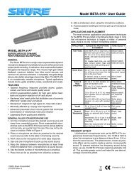
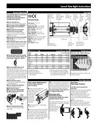
<strong>AD</strong>-<strong>16X</strong> – User’s <strong>Guide</strong>APOGEE ELECTRONICSStandard and Advanced Option RoutingWhen an X-Option card is installed, the <strong>AD</strong>-<strong>16X</strong> may be set to one of two output configurations, Standard Routingand Advanced Option Routing.When Standard routing is enabled, only one signal path is present – analog inputs routed simultaneously to alldigital outputs. When Advanced Option routing is enabled, two signal paths are present – 1) analog input to X-Option card outputs; 2) X-Option card inputs simultaneously to <strong>AD</strong>AT and AES outputs.<strong>AD</strong>-<strong>16X</strong>: Standard RoutingAESAESDevice<strong>AD</strong>-<strong>16X</strong>OpticalOpticalDeviceAnalog InCalLevelSoftLimitA to D& MetersUV22Option InX-FireWireorX-HDoption cardOption OutComputer<strong>AD</strong>-<strong>16X</strong>: Advanced Option RoutingAESAESDevice<strong>AD</strong>-<strong>16X</strong>OpticalOpticalDeviceAnalog InCalLevelSoftLimitA to D& MetersUV22Option InX-FireWireorX-HDoption cardOption OutComputerPlease see pages 9 & 10 for Advanced Option Routing examplesSwitching the <strong>AD</strong>-<strong>16X</strong> between Routing modes may only be accomplished when powering on the unit.To toggle between Standard and Advanced Option routing modes, press and hold the UP button while poweringon the unit; when Standard routing is enabled, “<strong>Apogee</strong> <strong>AD</strong>-<strong>16X</strong>” scrolls across the Sample Rate Display; whenAdvanced Option routing is enabled, “<strong>Apogee</strong> <strong>AD</strong>-<strong>16X</strong> 2.0” scrolls across the Sample Rate DisplayIMPORTANT NOTES CONCERNING <strong>AD</strong>VANDED OPTION ROUTING MODEAdvanced Option routing will modify the manner in which an X-HD equipped <strong>AD</strong>-<strong>16X</strong> is detected in Pro Tools,reflecting the additional available outputs. Please see the X-HD manual for details.8
<strong>AD</strong>-<strong>16X</strong> – User’s <strong>Guide</strong>APOGEE ELECTRONICSStandard and Advanced Option Routing - continuedDA-<strong>16X</strong>: Advanced Option Routing<strong>AD</strong>-<strong>16X</strong>: Advanced Option RoutingAESAESDeviceAES(input select)<strong>AD</strong>-<strong>16X</strong>OpticalDA-<strong>16X</strong>OpticalOpticalDeviceD to A& MetersCalLevelUV22A to D& MetersSoftLimitCalLevelOption InOption OutAnalog In Analog OutComputerX-HDoption cardX-HDoption with cardPro ToolsHDX-HDoption cardOption InOption OutAdvanced Option Routing –Additional Digital I/OWith Advanced Option routing, the <strong>AD</strong> and DA-<strong>16X</strong> offers additional digitalI/O to Digidesign HD or Firewire-based audio systems. As depictedin the routing diagram at left, when an X-HD card is installed in bothan <strong>AD</strong> and DA-<strong>16X</strong>, it becomes possible to route the DA-<strong>16X</strong>’s AES or<strong>AD</strong>AT inputs to a Pro Tools session while routing the <strong>AD</strong>-<strong>16X</strong>’s AES and<strong>AD</strong>AT outputs from the session. The <strong>AD</strong>-<strong>16X</strong> functions as a Digidesign192 with 16 analog inputs and 16 digital outputs while the DA-<strong>16X</strong> functionsas a 192 with 16 digital inputs and 16 analog outputs. Of course,the same functionality is possible with X-Firewire cards and a Firewirebasedaudio system.9
<strong>AD</strong>-<strong>16X</strong> – User’s <strong>Guide</strong>APOGEE ELECTRONICSStandard and Advanced Option Routing - continuedAdvanced Option Routing –Expanded Interface ChoicesWhen an X-Option card is installed in an <strong>AD</strong>-<strong>16X</strong>, Advanced Optionrouting offers the possibility to connect a second interface using the<strong>AD</strong>-<strong>16X</strong>’s digital I/O. As depicted in the routing diagram at right, the<strong>AD</strong>-<strong>16X</strong>’s analog inputs are routed to the Firewire audio device whilethe <strong>AD</strong>-<strong>16X</strong>’s digital outputs are routed from the Firewire device. Thesedigital outputs may be connected to a DA-<strong>16X</strong> or a MiniDAC to provideanalog output. In short, only one X-Option card is needed to connect an<strong>AD</strong>-<strong>16X</strong> and a D-to-A.<strong>AD</strong>-<strong>16X</strong>: Advanced Option RoutingAnalog Out<strong>AD</strong>-<strong>16X</strong>CalLevelSoftLimitA to D& MetersUV22X-FireWireoption cardAESOpticalDA-<strong>16X</strong>: Standard Routing(input select)DA-<strong>16X</strong>D to A& MetersCalLevelAESOpticalAnalog InOption InOption OutAESDeviceOpticalDeviceComputerwithFireWire400/80010
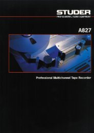
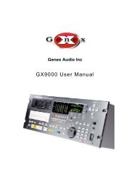
<strong>AD</strong>-<strong>16X</strong> – User’s <strong>Guide</strong>APOGEE ELECTRONICSConnections on the Rear Panel31 2 4 56 7891) IN 1-8 - This DB-25 connection accepts analoginputs 1-8; analog inputs are balanced line levelsignals at a nominal level adjustable between+4 dBu = -22 dBFs and -10 dBV = -10 dBFs.<strong>Apogee</strong>’s <strong>AD</strong>8-IFC breakout cables can connecthere to provide 8 XLR female connecters. (pinoutFigure 3).Pinout Diagram for Analog IN 1-8 and 9-162) IN 9-16 - This DB-25 connection accepts analoginputs 9-16. <strong>Apogee</strong>’s <strong>AD</strong>8-IFC breakout cablescan connect here to provide 8 XLR female connecters.(pinout Figure 3).3) OPTION - This slot is reserved for <strong>Apogee</strong>’s X-SeriesOption cards, which provide additional digitaloutput formats, such as FireWire or DigidesignHD.4) <strong>AD</strong>AT – S/MUX These Toslink connections provide<strong>AD</strong>AT or S/MUX format optical outputs; theformat employed is based on the <strong>AD</strong>-<strong>16X</strong> samplerate as indicated in Figure 4: also indicated arethe connections used for each format.5) AES OUT – This DB-25 connector provides 16channels of AES-EBU Single wire output and 8channels of Double wire output (pinout Figure 5).<strong>Apogee</strong>’s AES16-OP-IFC breakout cable can connecthere to provide 8 XLR male connectors.OpticalFormat44.1-48k<strong>AD</strong>AT:88.2-96kS/MUX 2:176.4-192kS/MUX 4:Rear Panel Optical ConnectorsPinout Diagram for AES OUT 1-16Figure 31 2 3 41-8 9-16 1-8 9-161-4 5-8 9-12 13-161-2 3-4 5-6 7-8Figure 46) WC IN - This BNC connection accepts a TTLLogic clock signal. Termination of the word clockinput may be engaged with an internal switch;please see “Internal Adjustments”.7) WC OUT - This BNC connection provides a TTLLogic clock signal output.8) WC IN Termination Switch - When this switch ispressed IN, a 75 ohm load is engaged across theword clock input; when the switch is OUT, the wordclock input is unterminated (Figure 6).9) AC - This IES connection accepts an AC input of100 to 240 VAC at a frequency of 50 to 60 Hz.WORD CLOCK IN, Termination SwitchTerminated switch positionUnterminated switch positionFigure 5Figure 611
<strong>AD</strong>-<strong>16X</strong> – User’s <strong>Guide</strong>APOGEE ELECTRONICSInternal AdjustmentsMIDI FIRMWARE UPDATE CONNECTORTo allow the greatest flexibility in the field, <strong>Apogee</strong> now employs a firmware update method usingstardard Midi protocol. You’ll need the following items to update the firmware of your <strong>Apogee</strong>device:• <strong>Apogee</strong>Updater program, available from <strong>Apogee</strong>’s website• New firmware file, also available from our website• Macintosh OSX 10.2 or higher or Windows XP computer• USB Midi interface, compatible with OS used. Please note that Midi interfaces withproprietary latency-reducing modes do not properly transmit System Exclusivedata such as this firmware update. Ensure that such modes are turned off beforeattempting to update firmware. USB Midi Interfaces such as the Edirol PC-300,where proprietary modes may not be turned off, are not compatible with this firmwareupdate method.1) To determine the version of firmware installed in the <strong>AD</strong>-<strong>16X</strong>, press the PREV button whilepowering on the unit.2) Install both the <strong>Apogee</strong>Updater and the newfirmware file onto a computer equipped with aUSB Midi Interface. It’s assumed that all driversnecessary for the proper test and operation of theMidi Interface have been installed.3) Connect the <strong>AD</strong>-<strong>16X</strong>’s Midi Update Connector toan output of the Midi Interface.4) On the <strong>AD</strong>-<strong>16X</strong>, simultaneously press the PREVand NEXT buttons while powering up the <strong>Apogee</strong>device; once the device has booted, releasethe PREV and NEXT buttons. When the signallevel LEDs begin to “dance”, the unit is ready toreceive data.MIDI updater5) Open the <strong>Apogee</strong>Updater application, and click on OPEN FILE. In the Navigation windowwhich appears, navigate to the new firmware file, select it, and click on OPEN.6) Click on DOWNLO<strong>AD</strong> TO UNIT.7) The complete update process takes 8 minutes; after about 1 minute, data transfer shouldbegin and the percentage completed displayed on the <strong>Apogee</strong>Updater panel shouldcorrespond to the percentage displayed on the <strong>AD</strong>-<strong>16X</strong> front panel.8) Once the download has reached 100%, wait for the unit to re-boot and the front panel toreturn to a normal operating state.9) Before proceeding, reset the unit by pressing DOWN while powering up the unit.12
<strong>AD</strong>-<strong>16X</strong> – User’s <strong>Guide</strong>APOGEE ELECTRONICSInternal Adjustments - continuedPOWER SWITCH SETTINGSJUMPER P13(as seen from front)DESCRIPTIONWhen AC power is applied to the input, the unit does notpower up immediately; to power on the unit,the POWERbutton must be pressed.When AC power is applied to the input, <strong>AD</strong>-<strong>16X</strong> powers onimmediately; nevertheless, the POWER switch is functional.P13 Jumper13
Features and Specifications• 16 channels of premium 24-bit <strong>AD</strong> conversion• Sample rates up to 192k• 16 channels of AES, <strong>AD</strong>AT/SMUX Output• Word Clock I/O• Optional HD card for direct connection to ProTools HD• Optional S800 FireWire card capable of sample rates up to 192k, compatible withOS X/Widows XP and all popular DAW’s• All option cards (X-FireWire and X-HD) facilitate connection of multiple units• “Soft Limit” for maximum digital level without overs(can be applied to a single channel or all channels)• “UV22HR” for superior dither of high resolution audio to 16-bit(can be applied to a channel pair or all channels)• Direct Digital Synthesis (DDS) using Big Ben’s C777 Clock Technology up to 192kHz• Adaptive Loop Filtering (ALF) for optimum clock performance and minimum jitter• Support for AES double wire and SMUX formats• Post A/D conversion level monitoring• Intuitive front panel calibration• Word Clock termination switchINPUTS• Analog in 1-8 Balanced, DSUB 25pin connector• Analog in 9-16 Balanced, DSUB 25pin connector• WC in: BNC 75 ohm with switchable terminationOUTPUTS• AES-EBU out x 8, transformer balanced, DSUB 25pinconnector (192k single wide compatible)• Optical: toslink x 4, supporting <strong>AD</strong>AT andSMUX protocol• WC out: BNC 75 ohmSPECS:• Sample rates internal: 44.1/48/88.2/96/176.4/192k• Sample rates external: 44.1/48/88.2/96/176.4/192k +/- 10%• Frequency response at 44.1 k : 5 - 20.000 Hz (+/- .2 dB)• Analog levels: 6 to 24dBu max through digital gainadjustment. (Compatible with -10dBV levels)• THD+N: -110 dB• Dynamic range: 120 dB A weighted• Power: 100 -240 VAC, 50 - 60 Hz, 65 WattOPTION SLOT• One x-type card can be installed, for Firewire,HD and or other future format connectivityDue to on-going development <strong>Apogee</strong> reserves the right to change all information and specifications without notice.
<strong>AD</strong>-<strong>16X</strong> USER’S GUIDE - v2.0 - January 2005Text conceived and delivered by: Roger RobindoreGraphics and illustration by: Sean McArthur