EEE 2101 Circuit Theory I - Laboratory 3 Linearity, Superposition ...
EEE 2101 Circuit Theory I - Laboratory 3 Linearity, Superposition ...
EEE 2101 Circuit Theory I - Laboratory 3 Linearity, Superposition ...

Create successful ePaper yourself
Turn your PDF publications into a flip-book with our unique Google optimized e-Paper software.
University of Bahçeşehir<br />
Engineering Faculty Name & Surname:<br />
Electrical and Electronics Engineering ID: Dept.<br />
Date:<br />
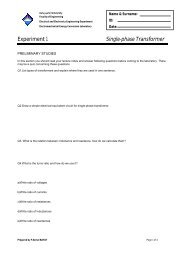
<strong>EEE</strong> <strong>2101</strong> <strong>Circuit</strong> <strong>Theory</strong> I - <strong>Laboratory</strong> 3<br />
<strong>Linearity</strong>, <strong>Superposition</strong>, Thevenin’s Theorem.<br />
Topics:<br />
<strong>Linearity</strong><br />
<strong>Superposition</strong> Theorem<br />
Thevenin’s Theorem<br />
Required Equipment and Components:<br />
DMM (Digital Multi Meter)<br />
Breadboard<br />
DC power supply<br />
Resistors<br />
Information:<br />
<strong>Linearity</strong> Property<br />
<strong>Linearity</strong> is the property of an element describing a linear relationship between cause and<br />
effect. The property is a combination of both the homogeneity property and additivity<br />
property.<br />
The homogeneity property requires that if the input (also called the excitation) is multiplied<br />
by a constant, then the output (also called the response) is multiplied by the same constant.<br />
For a resistor, for example, Ohm’s law relates the input i to the output v,<br />
v = iR<br />
(3.1)<br />
If the current is increased by a constant k, then the voltage increases correspondingly by k,<br />
that is,<br />
kiR = kv<br />
(3.2)<br />
<strong>EEE</strong> <strong>2101</strong> <strong>Circuit</strong> <strong>Theory</strong> I. Page 1 of 7
University of Bahçeşehir<br />
Engineering Faculty<br />
Electrical and Electronics Engineering Dept.<br />
The additivity property requires that the response to a sum of inputs is the sum of the<br />
responses to each input applied separately. Using the voltage-current relationship of a<br />
resistor, if<br />
v<br />
1<br />
1<br />
= i R<br />
(3.3)<br />
v<br />
2<br />
2<br />
= i R<br />
(3.4)<br />
then applying ( i1 + i2<br />
)R gives<br />
( i1 + i2<br />
) R = i1R<br />
+ i2R<br />
= v1<br />
v2<br />
v = + (3.5)<br />
In general, a circuit is linear if both additive and homogeneous. A linear circuit consists of<br />
only linear elements, linear dependent sources, and independent sources.<br />
<strong>Superposition</strong><br />
The superposition principle states that the voltage across (or current through) an element in a<br />
linear circuit is the algebraic sum of the voltages across (currents through) that element due<br />
to each independent source acting alone.<br />
To apply the superposition principle, we must keep two things in mind:<br />
• We consider one independent source at a time while all other independent sources are<br />
turned off. This implies that we replace every voltage source by 0 V (or a short<br />
circuit), and every current source by 0 A (or open circuit). This way we obtain a<br />
simpler and more manageable circuit.<br />
• Dependent sources are left intact because they are controlled by circuit variables.<br />
Steps to apply <strong>Superposition</strong> Principle:<br />
1. Turn off all independent sources except one source. Find the output (voltage<br />
or current) due to that active source using nodal or mesh analysis.<br />
2. Repeat step 1 for each of the other independent sources.<br />
3. Find the total contribution by adding algebraically all the contributions due to<br />
the independent sources.<br />
Thevenin’s Theorem<br />
It often occurs in practice that a particular element in a circuit is variable (usually called<br />
the load) while other elements are fixed. Each time the variable element is changed, the<br />
entire circuit has to be analyzed all over again. To avoid this problem, Thevenin’s<br />
theorem provides a technique by which the fixed part of the circuit is replaced by an<br />
equivalent circuit.<br />
<strong>EEE</strong> <strong>2101</strong> <strong>Circuit</strong> <strong>Theory</strong> I. Page 2 of 7
University of Bahçeşehir<br />
Engineering Faculty<br />
Electrical and Electronics Engineering Dept.<br />
According to Thevenin’s theorem, the linear circuit in Figure 3.1(a) can be replaced by<br />
that in Figure 3.1(b). (The load in Figure 3.1 may be a single resistor or another circuit).<br />
The circuit to the left of the terminals a-b in Figure 3.1(b) is known Thevenin’s<br />
equivalent circuit.<br />
Figure 3.1(a)<br />
Figure 3.1(b)<br />
Thevenin’s theorem states that a linear two terminal circuit can be replaced by an equivalent<br />
circuit consisting of a voltage sourceV th<br />
in series with a resistor R<br />
th<br />
where V<br />
th<br />
is the opencircuit<br />
voltage at the terminals and R<br />
th<br />
is the input or equivalent at the terminals when the<br />
independent sources are turned off.<br />
Our major concern right now is how to find the Thevenin equivalent voltage V<br />
th<br />
and<br />
resistance R<br />
th<br />
. To do so, suppose the two circuits in Figure 3.1 are equivalent. Two circuits<br />
are said to be equivalent if they have the same voltage-current relation at their terminals. Let<br />
us find out what will make the two circuits in Figure 3.1 equivalent. If the terminals a-b are<br />
made open-circuited (by removing the load), no current flows, so that the open-circuit<br />
voltage across the terminals a-b in Figure 3.1(a) must be equal to the voltage source V<br />
th<br />
in<br />
Figure 3.1(b), since the two circuits are equivalent. Thus V<br />
th<br />
is the open-circuit voltage<br />
across the terminals as shown in Figure 3.2(a); that is<br />
V<br />
th<br />
= v oc<br />
(3.6)<br />
Figure 3.2(a)<br />
<strong>EEE</strong> <strong>2101</strong> <strong>Circuit</strong> <strong>Theory</strong> I. Page 3 of 7
University of Bahçeşehir<br />
Engineering Faculty<br />
Electrical and Electronics Engineering Dept.<br />
Figure 3.2(b)<br />
Again, with the load disconnected and terminals a-b open-circuited, we turn off all<br />
independent sources. The input resistance (or equivalent resistance) of the dead circuit at the<br />
terminals a-b in Figure 3.1(a) must be equal to R in Figure 3.1(b) because the two circuits<br />
are equivalent. Thus, R<br />
th<br />
is the input resistance at the terminals when the independent<br />
sources are turned off in Figure 3.2(b) that is,<br />
R<br />
th<br />
= R in<br />
(3.7)<br />
To apply this idea in finding the Thevenin resistance R , we need to consider two cases.<br />
• If the network has no dependent sources, we turn off all independent sources. R<br />
th<br />
is<br />
the input resistance of the network looking between terminals a and b, as shown in<br />
Figure 3.2(b).<br />
th<br />
• If the network has dependent sources, we turn off all independent sources. As with<br />
superposition, dependent sources are not to be turned off because they are controlled<br />
by circuit variables. We apply a voltage source v<br />
0<br />
at terminals a and b and determine<br />
v0<br />
the resulting current i 0<br />
. Then R th<br />
= , as shown in Figure 3.3(a) . Alternatively, we<br />
i<br />
0<br />
may insert a current source i 0<br />
at terminals a-b as shown in Figure 3.3(b) and find<br />
v0<br />
the terminal voltage v<br />
0<br />
. Again R th<br />
= . Either of the two approaches will give the<br />
i<br />
same result. In either approach we may assume any value of v<br />
0<br />
and i 0<br />
.<br />
0<br />
th<br />
Figure 3.3(a)<br />
<strong>EEE</strong> <strong>2101</strong> <strong>Circuit</strong> <strong>Theory</strong> I. Page 4 of 7
University of Bahçeşehir<br />
Engineering Faculty<br />
Electrical and Electronics Engineering Dept.<br />
Figure 3.3(b)<br />
Preliminary Work:<br />
1. Do procedure part 2.<br />
2. Do procedure part 4.<br />
Procedure:<br />
1) Construct the network in figure in 3.4, measure the currents through R<br />
1<br />
, R2<br />
, R3<br />
then<br />
write them on table 3.1. Then measure the currents again for V1 = 8V<br />
and V<br />
2<br />
= 12V<br />
.<br />
Write the new values on table 3.1. Is the circuit linear or not If linear tell me, why<br />
Figure 3.4<br />
I<br />
R1<br />
I<br />
R2<br />
I<br />
R3<br />
For<br />
For<br />
For<br />
V1 = 4V<br />
V1 = 8V<br />
V1 = 12V<br />
Table 3.1<br />
<strong>EEE</strong> <strong>2101</strong> <strong>Circuit</strong> <strong>Theory</strong> I. Page 5 of 7
University of Bahçeşehir<br />
Engineering Faculty<br />
Electrical and Electronics Engineering Dept.<br />
……………………………………………………………………………………………<br />
……………………………………………………………………………………………<br />
2) Calculate the current passing through R<br />
3<br />
in figure 3.5 with superposition method<br />
and write the value on table 3.2. (Preliminary work)<br />
3) Construct the circuit in figure 3.5 and measure the current passing through R 3<br />
. Write<br />
the value on table 3.2.<br />
Figure 3.5<br />
I<br />
R3<br />
calculated<br />
R3<br />
I measured<br />
Table 3.2<br />
R is load, calculate the thevenin resistance ( )<br />
4) In figure 3.6,<br />
4<br />
R<br />
th<br />
and thevenin voltage<br />
( V<br />
th<br />
) then find the current passing through R<br />
4<br />
with thevenin theorem and write the<br />
value on table 3.3. .(Preliminary work)<br />
5) Construct the circuit in figure 3.6 and measure the current passing through R<br />
4<br />
. Write<br />
the value on table 3.3.<br />
I<br />
R4<br />
calculated<br />
R4<br />
Figure 3.6<br />
I measured ( R )<br />
( V )<br />
th<br />
th<br />
Table 3.3<br />
<strong>EEE</strong> <strong>2101</strong> <strong>Circuit</strong> <strong>Theory</strong> I. Page 6 of 7
University of Bahçeşehir<br />
Engineering Faculty<br />
Electrical and Electronics Engineering Dept.<br />
6) You have a circuit, which made only with resistances. Can we apply superposition<br />
theorem to power relation If no, why<br />
...............................................................................................................................<br />
…...........................................................................................................................<br />
Calculations:<br />
<strong>EEE</strong> <strong>2101</strong> <strong>Circuit</strong> <strong>Theory</strong> I. Page 7 of 7