56.461/1 Sauter Components B6R: Three-way valve with female ...
56.461/1 Sauter Components B6R: Three-way valve with female ...
56.461/1 Sauter Components B6R: Three-way valve with female ...

Create successful ePaper yourself
Turn your PDF publications into a flip-book with our unique Google optimized e-Paper software.
<strong>56.461</strong>/1<br />
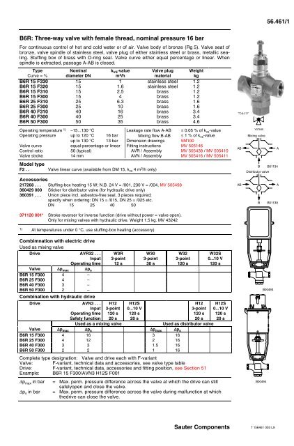
<strong>B6R</strong>: <strong>Three</strong>-<strong>way</strong> <strong>valve</strong> <strong>with</strong> <strong>female</strong> thread, nominal pressure 16 bar<br />
For continuous control of hot and cold water or of air. Valve body of bronze (Rg 5). Valve seat of<br />
bronze, <strong>valve</strong> spindle of stainless steel, <strong>valve</strong> plug of either stainless steel or brass, metallic sealing.<br />
Stuffing box of brass <strong>with</strong> O-ring seal. Valve curve either equal percentage or linear. When<br />
spindle is extracted, passage A-AB is closed.<br />
Type<br />
Curve = %<br />
Nominal<br />
diameter DN<br />
k VS -value<br />
m 3 /h<br />
Valve plug<br />
material<br />
Weight<br />
kg<br />
<strong>B6R</strong> 15 F330 15 1 stainless steel 1.2<br />
<strong>B6R</strong> 15 F320 15 1.6 stainless steel 1.2<br />
<strong>B6R</strong> 15 F310 15 2.5 brass 1.2<br />
<strong>B6R</strong> 15 F300 15 4 brass 1.2<br />
<strong>B6R</strong> 25 F310 25 6.3 brass 1.6<br />
<strong>B6R</strong> 25 F300 25 10 brass 1.6<br />
<strong>B6R</strong> 40 F310 40 16 brass 3.4<br />
<strong>B6R</strong> 40 F300 40 25 brass 3.4<br />
<strong>B6R</strong> 50 F300 50 35 brass 4.6<br />
Operating temperature 1) –15...130 °C Leakage rate flow A-AB ≤ 0.05 % of k vs -value<br />
Operating pressure up to 120 °C 16 bar Mixing flow B-AB ≤ 1 % of k vs -value<br />
up to 130 °C 13 bar Dimension drawings 5M100<br />
Valve curve equal-percentage or linear Fitting instructions MV 505146<br />
Control ratio 50 (typical) AVR / Assembly MV 505438 / MV 505410<br />
Valve stroke 14 mm AVN / Assembly MV 505416 / MV 505411<br />
Model type<br />
F2 . .<br />
Valve linear curve (available from DM 15, k vs 4 m 3 /h only)<br />
Accessories<br />
217268 . . . Stuffing-box heating 15 W; N.B. 24 V = /001, 230 V = /004, MV 505498<br />
360429 000 Sticker for distributor <strong>valve</strong> (for hydraulic drive only)<br />
360391 . . . Union piece incl. asbestos-free seal, 3 pieces required;<br />
specify when ordering: DN 15 = /015, DN 25 = /025 etc.<br />
DN 15 25 40 50<br />
371120 001* Stroke reverser for inverse function (drive <strong>with</strong>out power = <strong>valve</strong> open).<br />
Only for mixing <strong>valve</strong>s <strong>with</strong> hydraulic drive. Weight 1.5 kg. MV 43242<br />
1) At temperatures under 0 °C, use stuffing-box heating (accessory)<br />
AB<br />
AB<br />
Y07545<br />
Mixing <strong>valve</strong><br />
A<br />
B B01134<br />
Distributor <strong>valve</strong><br />
A<br />
B B01139<br />
Combimnation <strong>with</strong> electric drive<br />
Used as mixing <strong>valve</strong><br />
Drive AVR32 . . .<br />
Input<br />
Operating time<br />
Valve ∆p max ∆p s<br />
<strong>B6R</strong> 15 F300 4 –<br />
<strong>B6R</strong> 25 F300 4 –<br />
<strong>B6R</strong> 40 F300 3 –<br />
<strong>B6R</strong> 50 F300 2 –<br />
Combination <strong>with</strong> hydraulic drive<br />
Drive AVN3 . . .<br />
Input<br />
Operating time<br />
Safety function<br />
W3R<br />
3-point<br />
12 s<br />
H12<br />
3-point<br />
120 s<br />
20 s<br />
H12S<br />
0...10 V<br />
120 s<br />
20 s<br />
W30<br />
3-point<br />
30 s<br />
W32<br />
3-point<br />
120 s<br />
H12<br />
3-point<br />
120 s<br />
20 s<br />
Used as a mixing <strong>valve</strong><br />
Used as distributor <strong>valve</strong><br />
Valve ∆p max ∆p s ∆p max ∆p s<br />
<strong>B6R</strong> 15 F300 4 16 3 16<br />
<strong>B6R</strong> 25 F300 4 12 2 16<br />
<strong>B6R</strong> 40 F300 3 3 1.5 16<br />
<strong>B6R</strong> 50 F300 2 2 1 16<br />
Complete type designation: Valve and drive each <strong>with</strong> F-variant<br />
Valve: F-variant, technical data and accessories, see <strong>valve</strong> type table<br />
Drive: F-variant, technical data, accessories and fitting position, see Section 51<br />
Example: <strong>B6R</strong> 15 F300/AVN3 H12S F001<br />
∆p max in bar<br />
∆p s in bar<br />
W32S<br />
0...10 V<br />
120 s<br />
H12S<br />
0...10 V<br />
120 s<br />
20 s<br />
= Max. perm. pressure difference across the <strong>valve</strong> at which the drive can still<br />
safelyopen and close the <strong>valve</strong>.<br />
= Max. perm. pressure difference across the <strong>valve</strong> during malfunction at which<br />
thedrive can close the <strong>valve</strong>.<br />
B00494<br />
B00493<br />
<strong>Sauter</strong> <strong>Components</strong><br />
7 156461 003 L9
<strong>56.461</strong>/2 <strong>B6R</strong><br />
Operation<br />
Using an electric or hydraulic drive, the <strong>valve</strong> can be moved to any position.<br />
Used as a mixing <strong>valve</strong><br />
possible <strong>with</strong> electric or hydraulic drive<br />
Used as a distributor <strong>valve</strong><br />
possible only <strong>with</strong> hydraulic drive<br />
AB<br />
A<br />
AB<br />
A<br />
B<br />
B01134<br />
B<br />
B01139<br />
Engineering and installation notes<br />
Can be fitted in any position except facing downwards (see relevant drive). When fitting the drive to<br />
the <strong>valve</strong>, care must be taken not to turn the <strong>valve</strong> plug on the two stops (seat), thus damaging the<br />
seal.<br />
Additional technical details<br />
Type<br />
∆p v<br />
<strong>B6R</strong> 15 F . 30 4 (3)<br />
<strong>B6R</strong> 15 F . 20 4 (3)<br />
<strong>B6R</strong> 15 F . 10 4 (3)<br />
<strong>B6R</strong> 15 F . 00 4 (3)<br />
<strong>B6R</strong> 25 F . 10 4 (2)<br />
<strong>B6R</strong> 25 F . 00 4 (2)<br />
<strong>B6R</strong> 40 F . 10 3 (1.5)<br />
<strong>B6R</strong> 40 F . 00 3 (1.5)<br />
<strong>B6R</strong> 50 F . 00 2 (1)<br />
∆p v in bar = max. pressure difference across the <strong>valve</strong> in any stroke position, limited by the noise<br />
level and erosion (max. values <strong>with</strong>out being limited by the force of the drive).<br />
The values in brackets apply when used as a distributor <strong>valve</strong>.<br />
Technical information<br />
• Pressure and temperature specifications DIN 2401<br />
• Flow parameters VDI/VDE 2173<br />
• <strong>Sauter</strong> slide rule for <strong>valve</strong> sizing 7 090011 003<br />
• Slide rule manual 7 000129 003<br />
• Technical manual ’Manipulating units' 7 000477 003<br />
Parameters, Notes on installation, Control,<br />
Pneumatic manipulating units, General information<br />
<strong>Sauter</strong> <strong>Components</strong><br />
7 156461 003 K9
<strong>B6R</strong> <strong>56.461</strong>/3<br />
Additional details on accessories<br />
217268/ . . . Heating for stuffing box 15 W; housing of light metal; degree of protection IP 54;<br />
connecting cable 3 × 0.75 mm 2 , earth connection, 1 m in length, cable end sleeves.<br />
360429 Sheet of 21 adhesive labels for flow change; for hydraulic drive only,see combinations.<br />
Additional details on model types<br />
Valve body <strong>with</strong> <strong>female</strong> thread; metallic seal; flat seal of copper at the body; stuffing-box <strong>with</strong> O-ring of<br />
ethylene-propylene.<br />
Material numbers as per DIN<br />
DIN material no.<br />
DIN description<br />
Valve body 2.1096.01 G-Cu Sn 5 Zn Pb (Rg 5)<br />
Valve seat 2.1096.01 G-Cu Sn 5 Zn Pb (Rg 5)<br />
Spindle 1.4305 X 12 Cr Ni S 18 8<br />
Plug 2.0402.26 Cu Zn 40 Pb 2 F43<br />
Plug V6R 15 F.20...F.30 1.4305 X 12 Cr Ni S 18 8<br />
Stuffing box 2.0401.10 Cu Zn 39 Pb 3 F36<br />
Additional combinations<br />
Drive AVN3 . . .<br />
Input<br />
Running time<br />
Safety function H110<br />
Valve<br />
H10<br />
3-point<br />
30 s<br />
8 s<br />
Used as a mixing <strong>valve</strong><br />
H10S<br />
0...10 V–<br />
30 s<br />
8 s<br />
∆pmax<br />
∆ps<br />
<strong>B6R</strong> 15 F300 4 16<br />
<strong>B6R</strong> 25 F300 4 12<br />
<strong>B6R</strong> 40 F300 3 3<br />
<strong>B6R</strong> 50 F300 2 2<br />
Explanation of terms used<br />
∆p v :<br />
Maximum permissible pressure difference across the <strong>valve</strong> in any stroke position, limited by the noise<br />
level and erosion.<br />
The <strong>valve</strong> as a traversed element is defined by this parameter specifically in its hydraulic behaviour.<br />
By monitoring cavitation, erosion and the noise thus produced, improvements can be achieved in both<br />
life expectancy and durability.<br />
∆p max :<br />
Maximum permissible pressure difference across the <strong>valve</strong> at which the drive can firmly open and<br />
close the <strong>valve</strong>.<br />
Static pressure and fluidic influences are taken into account. This value helps to maintain smooth<br />
stroke action and <strong>valve</strong> sealing. In doing so, the <strong>valve</strong>'s ∆p v value is not exceeded.<br />
∆p s :<br />
Maximum permissible pressure difference across the <strong>valve</strong> in the event of a malfunction (e.g. power<br />
failure, excess temperature or pressure, burst pipe) at which the drive can firmly close the <strong>valve</strong> and,<br />
if necessary, hold the full operating pressure against atmospheric pressure. Since this is a safety<br />
function <strong>with</strong> ‘fast' stroke, ∆p s can be larger than ∆p max or, respectively, ∆p v . The resultant fluidic<br />
disturbances are soon overcome and play a minor role here.<br />
On the three-<strong>way</strong> <strong>valve</strong>s, the values apply only for the control passage.<br />
∆p stat :<br />
Line pressure behind the <strong>valve</strong>. This corresponds largely to the dead pressure when the pump is<br />
switched off, e.g. due to the level of liquid in the plant, an increase in pressure via the pressure store,<br />
steam pressure etc.<br />
On <strong>valve</strong>s that close <strong>with</strong> the pressure, the static pressure plus the pump pressure should be used.<br />
<strong>Sauter</strong> <strong>Components</strong><br />
7 156461 003 J6
<strong>56.461</strong>/4 <strong>B6R</strong><br />
Dimension drawings 5M100<br />
<strong>B6R</strong><br />
Ø38<br />
M10<br />
H<br />
99<br />
c<br />
a<br />
Rp<br />
(Zubehör)<br />
(accessoire)<br />
(accessory)<br />
G(DN)<br />
f<br />
Hub<br />
Course<br />
Stroke<br />
14mm<br />
L<br />
L1<br />
15<br />
25<br />
40<br />
50<br />
DN<br />
1/2"<br />
1"<br />
1 1/2"<br />
2"<br />
a<br />
59<br />
69<br />
76<br />
98<br />
c<br />
29<br />
33<br />
47<br />
57<br />
f<br />
37<br />
43<br />
53<br />
57<br />
H L L1 G Rp<br />
187 85 159 1/2 1/2<br />
201 110 196 1 1<br />
222 150 256 1 1/2 1 1/2<br />
254 180 294 2 2<br />
M361065a<br />
AVR32 W3.<br />
AVN3 H12, H112<br />
(AVN3 H10, H110)<br />
> 100<br />
c 296<br />
102 > 150<br />
379<br />
(394)<br />
c<br />
> 100<br />
92 > 100<br />
B01163<br />
B01164<br />
Fitting width:<br />
Stroke reverser<br />
Use measurement ‘c' from <strong>valve</strong> dimension<br />
drawing<br />
Note increase in length of 94 mm due to<br />
stroke reverser<br />
(Accessory no. 371120)<br />
94<br />
Printed in Switzerland<br />
Right of amendment reserved<br />
N.B.: A comma between cardinal<br />
numbers denotes a decimal point<br />
Fr. <strong>Sauter</strong> AG, CH-4016 Basle<br />
7 156461 003 E9<br />
120<br />
B01147<br />
<strong>Sauter</strong> <strong>Components</strong>