

OMRON Sysdrive 3G3HV - Detector Cooling Section
OMRON Sysdrive 3G3HV - Detector Cooling Section
OMRON Sysdrive 3G3HV - Detector Cooling Section

Create successful ePaper yourself
Turn your PDF publications into a flip-book with our unique Google optimized e-Paper software.
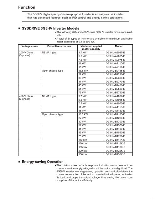
Function<br />
The <strong>3G3HV</strong> High-capacity General-purpose Inverter is an easy-to-use inverter<br />
that has advanced features, such as PID control and energy-saving operations.<br />
SYSDRIVE <strong>3G3HV</strong> Inverter Models<br />
• The following 200- and 400-V class <strong>3G3HV</strong> Inverter models are available.<br />
• A total of 21 types of Inverter are available for maximum applicable<br />
motor capacities of 0.4 to 300 kW.<br />
Voltage class Protective structure Maximum applied<br />
Model<br />
motor capacity<br />
200-V Class NEMA1 type 3.7 kW <strong>3G3HV</strong>-A2037-E<br />
(3-phase)<br />
5.5 kW <strong>3G3HV</strong>-A2055-E<br />
7.5 kW <strong>3G3HV</strong>-A2075-E<br />
11 kW <strong>3G3HV</strong>-A2110-E<br />
15 kW <strong>3G3HV</strong>-A2150-E<br />
Open chassis type 18.5 kW <strong>3G3HV</strong>-B2185-E<br />
22 kW <strong>3G3HV</strong>-B2220-E<br />
30 kW <strong>3G3HV</strong>-B2300-E<br />
37 kW <strong>3G3HV</strong>-B2370-E<br />
45 kW <strong>3G3HV</strong>-B2450-E<br />
55 kW <strong>3G3HV</strong>-B2550-E<br />
75 kW <strong>3G3HV</strong>-B2750-E<br />
400-V Class NEMA1 type 3.7 kW <strong>3G3HV</strong>-A4037-E<br />
(3-phase)<br />
5.5 kW <strong>3G3HV</strong>-A4055-E<br />
7.5 kW <strong>3G3HV</strong>-A4075-E<br />
11 kW <strong>3G3HV</strong>-A4110-E<br />
15 kW <strong>3G3HV</strong>-A4150-E<br />
Open chassis type 18.5 kW <strong>3G3HV</strong>-B4185-E<br />
22 kW <strong>3G3HV</strong>-B4220-E<br />
30 kW <strong>3G3HV</strong>-B4300-E<br />
37 kW <strong>3G3HV</strong>-B4370-E<br />
45 kW <strong>3G3HV</strong>-B4450-E<br />
55 kW <strong>3G3HV</strong>-B4550-E<br />
75 kW <strong>3G3HV</strong>-B4750-E<br />
110 kW <strong>3G3HV</strong>-B411K-E<br />
160 kW <strong>3G3HV</strong>-B416K-E<br />
185 kW <strong>3G3HV</strong>-B418K-E<br />
220 kW <strong>3G3HV</strong>-B422K-E<br />
300 kW <strong>3G3HV</strong>-B430K-E<br />
Energy-saving Operation<br />
• The rotation speed of a three-phase induction motor does not decrease<br />
when the supply voltage drops if the motor has a light load. The<br />
<strong>3G3HV</strong> Inverter in energy-saving operation automatically detects the<br />
current consumption of the motor connected to the Inverter, estimates<br />
its load, and drops the output voltage, thus saving the power consumption<br />
of the motor efficiently.
• Use the auto-tuning function of the Inverter in energy-saving mode to<br />
reduce the power consumption of the motor most efficiently if the ratings<br />
of the motor are unknown.<br />
• The Inverter in energy-saving mode is ideal for the following applications.<br />
Rotation control of fans and blowers<br />
Flow control of pumps<br />
Control of machines with variable loads, such as metal-working machines, wood-working<br />
machines, and food-processing machines<br />
Control of machines that mainly operate with light loads<br />
PID Control<br />
Speed control:<br />
Pressure control:<br />
• The Inverter has a PID control function, thus performing follow-up control<br />
with ease.<br />
• Follow-up control is a control method in which the Inverter uses a sensor<br />
and senses the rotation speed of the motor and changes the output<br />
frequency to control the rotation speed of the motor.<br />
• Follow-up control can be applied to a variety of control operations.<br />
• PID control is ideal for the following applications.<br />
With a speed sensor, such as a tachometric generator, the Inverter<br />
regulates the rotation speed of the motor regardless of the load of<br />
the motor or synchronizes the rotation speed of the motor with that<br />
of another motor.<br />
With a pressure sensor, the Inverter performs constant pressure<br />
control.<br />
Current control: With a current sensor, the Inverter performs precise current control.<br />
Temperature control: With a temperature sensor and fan, the Inverter performs temperature<br />
control.<br />
Frequency Reference<br />
• The following three types of frequency references are possible to control<br />
the output frequency of the Inverter.<br />
Numeric input from the Digital Operator of the Inverter<br />
Voltage input within a range from 0 to 10 V<br />
Current input within a range from 4 to 20 mA<br />
The Inverter can use one of the above if it is designated with parameters.<br />
• A maximum of four frequency references can be registered with the<br />
Inverter. With remote multi-step input, the Inverter can be in multi-step<br />
speed operation with a maximum of four speed steps.<br />
Frequency Jump<br />
• The frequency jump function prevents the Inverter from generating<br />
any frequency that causes the machine to resonate.<br />
Acceleration/Deceleration Time Settings<br />
• The acceleration time and deceleration time of the Inverter can be set<br />
independently within a range of 0.0 to 3,600 s.
• Two acceleration times and two deceleration times can be set with the<br />
Inverter, any of which can be selected with remote output.<br />
V/f Settings<br />
• Select a V/f pattern out of the 15 V/f patterns preset with the Inverter<br />
according to the application.<br />
• An optional V/f pattern can be set with the Inverter.<br />
Monitor Function<br />
• The following items can be monitored with the Digital Operator.<br />
Frequency reference, output frequency, output current, output voltage, DC voltage, output<br />
power, status of input terminals, inverter status, power interruption error, PROM number,<br />
total operating time, and PID feedback value<br />
Low Noise (3.7- to 160-kW Models)<br />
• The output transistor of the Inverter is an IGBT (insulated gate bipolar<br />
transistor). Using a sine-wave PWM method with a high-frequency<br />
carrier, the motor does not generate metallic noise.<br />
High Torque at Low Output Frequency Range<br />
• A torque rate of 150% can be achieved even in a low speed range<br />
where output frequency is only 3 Hz.<br />
Automatic Torque Boost<br />
• The Inverter automatically adjusts the output according to the required<br />
torque of the motor that is rotating at constant or accelerative speed,<br />
thus ensuring the powerful rotation of the motor.<br />
Harmonic Countermeasures (3.7- to 160-kW Models)<br />
• DC reactors (optional) can be connected to 3.7- to 15-kW models.<br />
• Models of 18.5- to 160-kW have a built-in DC reactor and also employ<br />
12-pulse rectification, which suppresses harmonics better than a<br />
reactor.
Nomenclature<br />
Panel<br />
Protection cover (top and bottom)<br />
Mounting hole<br />
Heat sink<br />
Digital Operator<br />
Front cover<br />
Terminals<br />
Terminals (with Front Cover Removed)<br />
Example: 200-V Class Inverter with 3.7-kW Output<br />
Control<br />
circuit<br />
terminals<br />
Power input Braking Resistor Motor output<br />
Main circuit<br />
terminals
Digital Operator<br />
Easy-setting indicators<br />
Displays basic parameter<br />
constants and monitor items.<br />
Mode Key<br />
Switches basic parameter<br />
constant and monitor items.<br />
Operation Mode Selection Key<br />
Switches between Digital Operator<br />
and external terminal operations.<br />
Run Key<br />
Starts the Inverter.<br />
Fref Fout Iout kWout<br />
F/R Montr Accel Decel<br />
Vmtr V/F Fgain Fbias<br />
FLA PID kWsa<br />
v<br />
LOCAL<br />
REMOTE<br />
RUN<br />
REMOTE<br />
SEQ REF<br />
PRGM<br />
DIGITAL OPERATOR PJVOP131E<br />
STOP<br />
RESET<br />
Operation Mode Indicators<br />
External Operation:<br />
Lit when operating references from external<br />
terminals are in effect.<br />
Analog Input:<br />
Lit when high-frequency references from<br />
external analog terminals are in effect.<br />
Data Display<br />
Displays frequency reference, output<br />
frequency, output current,<br />
constant set values, Inverter status,<br />
etc.<br />
Enter Key<br />
Enters set value when pressed after<br />
constant has been set.<br />
Increment Key<br />
Increments numbers when pressed<br />
during setting of constant number<br />
and constant data.<br />
Decrement Key<br />
Decrements numbers when pressed<br />
during setting of constant number<br />
and constant data.<br />
Stop/Reset Key<br />
Stops the Inverter. Also resets after<br />
alarm has been generated.
Dimensions<br />
<strong>3G3HV</strong>-A2037/-A4037<br />
External Dimensions<br />
Two, 5.5-dia.<br />
Mounting Dimensions<br />
Four, M5<br />
<strong>3G3HV</strong>-A2055/-A2075/-A4055/-A4075<br />
External Dimensions<br />
Two, 7-dia.<br />
Mounting Dimensions<br />
Four, M5<br />
8
<strong>3G3HV</strong>-A2110/-A2150/-A4110/-A4150<br />
External Dimensions<br />
Two, 7-dia.<br />
Mounting Dimensions<br />
Four, M5<br />
Note *The dashed lines apply only to the A2150.<br />
<strong>3G3HV</strong>-B2185/-B2220/-B4185/-B4220/-B4300/-B4450<br />
External Dimensions<br />
Mounting Dimensions<br />
Four, M5<br />
Voltage class Model <strong>3G3HV</strong>- Dimensions (mm)<br />
H H1 D1<br />
200-V B2185/B2220 450 435 174.5<br />
400-V B4185/B4220 450 435 174.5<br />
B4300/B4370/B445 526 610 175<br />
0
<strong>3G3HV</strong>-B2300/-B2370/-B2450/-B2550/-B4550/-B4750<br />
External Dimensions<br />
Two, 12-dia.<br />
Mounting Dimensions<br />
Four, M10<br />
Voltage class Model <strong>3G3HV</strong>- Dimensions (mm)<br />
W H W1 H1<br />
200-V B2300/B2370 425 675 320 650<br />
B2450/B2550 475 800 370 775<br />
400-V B4550/B4750 455 820 350 795
<strong>3G3HV</strong>-B2750/-B411K/-B416K<br />
External Dimensions<br />
Two, 14 dia.<br />
Mounting Dimensions<br />
Four, M12<br />
Voltage class Model <strong>3G3HV</strong>- Dimensions (mm)<br />
D D2 W2<br />
200-V B2750 400 max. 158 695<br />
400-V B411K 375 max. 130 695<br />
B416K 400 max. 158 695
<strong>3G3HV</strong>-B418K/-B422K<br />
External Dimensions<br />
Six, 14 dia.<br />
Mounting Dimensions<br />
Six, M12<br />
<strong>3G3HV</strong>-B430K<br />
External Dimensions<br />
Six, 14 dia.<br />
Mounting Dimensions<br />
Six, M12
Installation Conditions<br />
Cautions and Warnings<br />
!<br />
Caution<br />
Don’t install the Inverter near combustible objects. Otherwise, a fire<br />
may occur.<br />
!<br />
!<br />
!<br />
!<br />
!<br />
!<br />
Caution<br />
Caution<br />
Caution<br />
Caution<br />
WARNING<br />
WARNING<br />
Don’t install the Inverter in a place where it is exposed to dust or rubbish.<br />
Otherwise, a fire may occur.<br />
Prevent any foreign matter from entering into the Inverter. Otherwise,<br />
a fire or equipment trouble may occur.<br />
Provide specified spaces between the Inverter and the control panel<br />
and also between the Inverter and other units. Otherwise, a fire or<br />
equipment trouble may occur.<br />
Don’t apply any strong impact to the Inverter. Otherwise, damage to<br />
the Inverter or cause equipment trouble may occur.<br />
Install a stopping device for safety purposes. Otherwise, an injury may<br />
occur. (The holding brake is not a stopping device for safety<br />
purposes.)<br />
Install an external emergency stop device so that the power supply<br />
can be turned OFF and operation can be stopped instantaneously in<br />
case of an emergency. Otherwise, an injury may occur.<br />
Direction and Space<br />
• Install the Inverter on a vertical surface so that the characters on the<br />
nameplate are oriented upward.<br />
• When installing the Inverter, always provide the following installation<br />
space to allow normal heat dissipation from the Inverter.<br />
W = 30 mm min.<br />
120 mm min.<br />
Air<br />
Inverter Inverter Inverter<br />
Side<br />
120 mm min.<br />
Air
Installation Site<br />
NEMA1 Type<br />
Open Chassis Type<br />
• Install the Inverter under the following conditions.<br />
Ambient temperature for operation: –10° to 40°C<br />
Humidity: 90% RH or less (no condensation)<br />
Ambient temperature for operation: –10°C to 45°C<br />
Humidity: 90% RH or less (no condensation)<br />
Note A protection cover is attached to the top and bottom of the Inverter. Be sure to remove the<br />
protection covers before installing the 200- or 400-V Class Inverter that has an output of<br />
15 kW or less to a panel.<br />
• Install the Inverter in a clean location free from oil mist and dust. Alternatively,<br />
install it in a totally enclosed panel that is completely shielded<br />
from floating dust.<br />
• When installing or operating the Inverter, always take special care so<br />
that metal powder, oil, water, or other foreign matter does not get into<br />
the Inverter.<br />
• Do not install the Inverter on inflammable material such as wood.<br />
Ambient Temperature Control<br />
• To enhance operation reliability, the Inverter should be installed in an<br />
environment free from extreme temperature rises.<br />
• If the Inverter is installed in an enclosed environment such as a box,<br />
use a cooling fan or air conditioner to maintain the internal air temperature<br />
below 45°C.<br />
Protecting Inverter from Foreign Matter during Installation<br />
• Place a cover over the Inverter during installation to shield it from metal<br />
power produced by drilling.<br />
• Upon completion of installation, always remove the cover from the Inverter.<br />
Otherwise, ventilation will be affected, causing the Inverter to<br />
overheat.
Wiring<br />
Cautions and Warnings<br />
!<br />
WARNING Be sure that the power supply is turned OFF before wiring. Otherwise, an<br />
electric shock may occur.<br />
!<br />
WARNING Wiring must be performed by authorized persons specialized in electrical<br />
work. Otherwise, an electric shock or fire may occur.<br />
!<br />
WARNING Be sure to check for proper operation after wiring the emergency stop circuit.<br />
Otherwise, physical injury may occur.<br />
!<br />
WARNING Be sure to ground the ground terminal. Otherwise, an electric shock or fire<br />
may occur.<br />
!<br />
WARNING Be sure to confirm that the rated voltage of the Inverter coincides with the<br />
voltage of the AC power supply. Otherwise, a fire, injury, or equipment<br />
trouble may occur.<br />
!<br />
WARNING When connecting the dynamic braking resistor, Dynamic Braking Resistor<br />
Unit, or Braking Unit, be sure to follow the instructions specified in the Operation<br />
Manual. Otherwise, a fire may occur.<br />
!<br />
!<br />
WARNING Be sure to wire correctly. Otherwise, injury or equipment damage may occur.<br />
WARNING Be sure to firmly tighten the screws on the terminal block. Otherwise, a fire,<br />
injury, or equipment damage may occur.<br />
!<br />
Caution<br />
Don’t connect the AC power to the output terminal T1 (U), T2 (V), or T3 (W).<br />
Otherwise, equipment damage or trouble may occur.
Removing and Mounting the Front Cover<br />
Remove the front cover to wire the terminals. Remove the Digital Operator from<br />
the front cover before removing the front cover. Do not remove or mount the<br />
front cover without first removing the Digital Operator, otherwise Digital Operator<br />
may malfunction due to imperfect contact.<br />
Removing the Digital Operator<br />
• Press the lever on the side of the Digital Operator in the arrow 1<br />
direction to unlock the Digital Operator and lift the Digital Operator in<br />
the arrow 2 direction to remove the Digital Operator as shown in the<br />
following illustration.<br />
Removing the Front Cover<br />
• Press the left and right sides of the front cover in the arrow 1 directions<br />
and lift the bottom of the cover in the arrow 2 direction to<br />
remove the front cover as shown in the following illustration.<br />
Mounting the Front Cover<br />
• Mount the front cover to the Inverter by taking in reverse order to the<br />
steps to remove the front cover after wiring the terminals.
• Do not mount the front cover with the Digital Operator attached to the<br />
front cover, otherwise Digital Operator may malfunction due to<br />
imperfect contact.<br />
• Insert the tab of the upper part of the front cover into the groove of the<br />
Inverter and press the lower part of the front cover onto the Inverter<br />
until the front cover snaps shut.<br />
Attaching the Digital Operator<br />
• Hook the Digital Operator on clicks A of the front cover in the arrow 1<br />
direction as shown in the following illustration.<br />
• Press the Digital Operator in the arrow 2 direction until it snaps shut<br />
with clicks B.<br />
Clicks A<br />
Clicks B<br />
Note Do not remove or attach the Digital Operator or mount or remove the front cover using<br />
methods other than those mentioned above, otherwise the Inverter may malfunction due<br />
to imperfect contact or break.<br />
Removing the Front Cover of the Inverter with 18.5-kW Output or<br />
More<br />
• The front cover can be removed without removing the Digital Operator<br />
from the Inverter provided that the Inverter is a model with an output of<br />
18.5 kW or more.<br />
• Loosen the four screws of the front cover and move the front cover<br />
slightly upwards to remove the front cover.
Terminals<br />
Terminal Block Configuration (200-V Class with 3.7-kW Output)<br />
Control<br />
circuit terminals<br />
Power input Braking Resistor Motor output<br />
Main circuit<br />
terminals<br />
Main Circuit Terminals<br />
200-V Class<br />
Model <strong>3G3HV</strong>- A2037 to A2075 A2110 to A2150 B2185 to B2750<br />
Maximum<br />
applied motor<br />
3.7 to 7.5 kW 11 to 15 kW 18.5 to 75 kW<br />
capacity<br />
L1 (R) Power supply input terminals, 3-phase, 200 to 230 Power supply input<br />
L2 (S)<br />
VAC, 50/60 Hz<br />
terminals, 3-phase, 200 to<br />
230 VAC, 50/60 Hz<br />
L3 (T)<br />
L11 (R1) ---<br />
L21 (S1)<br />
L31 (T1)<br />
T1 (U) Motor output terminals, 3-phase, 200 to 230 VAC (correspond to input voltage)<br />
T2 (V)<br />
T3 (W)<br />
B1<br />
Braking Resistor Unit ---<br />
B2<br />
connection terminals<br />
+ 1<br />
DC reactor connection DC reactor connection ---<br />
terminal ( + 1- + 2)<br />
terminal ( + 1- +<br />
2)<br />
+ 2<br />
DC power supply input<br />
DC power supply input<br />
–<br />
terminal ( + 1- – ) terminal ( + 1- – )<br />
+ Braking Unit connection<br />
3<br />
---<br />
terminal ( + 3- – )<br />
Ground the terminal at a resistance of less than 100 Ω.
400-V Class<br />
Model <strong>3G3HV</strong>- A4037 to A4150 B4185 to B416K B418K to B430K<br />
Maximum<br />
applied motor<br />
3.7 to 15 kW 18.5 to 160 kW 185 to 300 kW<br />
capacity<br />
L1 (R) Power supply input Power supply input Power supply input<br />
L2 (S) terminals, 3-phase, 380 to terminals, 3-phase, 380 to terminals, 3-phase, 380 to<br />
460 VAC, 50/60 Hz 460 VAC, 50/60 Hz 460 VAC, 50/60 Hz<br />
L3 (T)<br />
L11 (R1) --- ---<br />
L21 (S1)<br />
L31 (T1)<br />
T1 (U) Motor output terminals, 3-phase, 380 to 460 VAC (correspond to input voltage)<br />
T2 (V)<br />
T3 (W)<br />
B1<br />
Braking Resistor Unit ---<br />
B2<br />
connection terminals<br />
+ 1<br />
DC reactor connection --- DC power supply input<br />
terminal ( + 1- + 2)<br />
terminal ( + 1- – )<br />
+<br />
–<br />
2<br />
+ 3<br />
---<br />
DC power supply input<br />
terminal ( + 1- – )<br />
Ground the terminal at a resistance of less than 10 Ω.<br />
---<br />
Braking Unit connection<br />
terminal ( + 3- – )
Control Circuit Terminals for All <strong>3G3HV</strong> Models<br />
Symbol Name Function Signal level<br />
Input S1 Forward run/Stop Stops at OFF. Photocoupler<br />
S2 Multi-function input 1 (S2) Set by constant n035 (reverse run/stop).<br />
24 VDC, 8 mA<br />
Output<br />
S3 Multi-function input 2 (S3) Set by constant n036 (external error a).<br />
S4 Multi-function input 3 (S4) Set by constant n037 (error reset).<br />
S5 Multi-function input 4 (S5) Set by constant n038 (multi-step speed reference<br />
1).<br />
S6 Multi-function input 5 (S6) Set by constant n039 (multi-step speed reference<br />
2).<br />
SC Sequence input common Common for S1 to S6.<br />
FS Frequency reference power supply DC power supply for frequency reference. 15 VDC, 20<br />
mA<br />
FV Frequency reference input (voltage) Voltage input terminal for frequency reference.<br />
FI Frequency reference input (current) Current input terminal for frequency reference.<br />
0 to 10 VDC<br />
(20 kΩ)<br />
4 to 20 mA<br />
(250 kΩ)<br />
FC Frequency reference input common Common for FV, F1. ---<br />
E<br />
(G)<br />
Shielded wire connection ground Shielded terminal for sequence and frequency<br />
reference inputs. (see note 2)<br />
---<br />
MA Multi-function contact output 1 (normally<br />
Set by constant n040 (error)<br />
Contact outmally<br />
open)<br />
put<br />
MB Multi-function contact output 1 (nor-<br />
30 VDC, 1 A<br />
closed)<br />
max.<br />
250 VAC, 1 A<br />
MC Multi-function contact output 1 common<br />
Common for MA, MB<br />
max.<br />
M1 Multi-function contact output 2 (normally<br />
Set by constant n041 (running)<br />
open)<br />
M2 Multi-function contact output 2 common<br />
Common for M1<br />
AM Multi-function analog output Set by constant n048 (output frequency) 0 to 10 VDC,<br />
AC Multi-function analog output common<br />
Common for AM<br />
2 mA<br />
Note<br />
Note<br />
1. The settings shown in parentheses in the “Function” column for the multi-function inputs<br />
and multi-function contact outputs indicate default settings.<br />
2. Do not connect a grounding wire to the E (G) terminal. Connect the grounding wire to<br />
the ground terminal of the main circuit terminals.
Standard Connection Diagram<br />
For Inverter Models of 200- to 400-V Class with 3.7- to 15-kW Output<br />
DC reactor (External<br />
connection possible)<br />
Braking Resistor Unit<br />
(see note) (optional)<br />
Three-phase,<br />
200 (400) VAC<br />
Forward rotation/Stop<br />
Multi-function<br />
input 1<br />
Multi-function<br />
input 2<br />
Multi-function<br />
input 3<br />
Multi-function<br />
input 4<br />
Multi-function<br />
input 5<br />
Common<br />
L1 (R)<br />
L2 (S)<br />
L3 (T)<br />
T1 (U)<br />
T2 (V)<br />
T3 (W)<br />
Three-phase induction<br />
motor<br />
Multi-function contact output 1<br />
(Normally open contact)<br />
(Normally closed contact)<br />
Common<br />
Multi-function contact output 2<br />
Common<br />
Shielded wire<br />
Variable resistor for<br />
frequency reference<br />
(voltage input)<br />
Multi-function analog output<br />
Common<br />
Voltmeter<br />
Frequency reference<br />
(current input)<br />
Note:<br />
These terminals of the <strong>3G3HV</strong>-A2110 and <strong>3G3HV</strong>-A2150<br />
connect to the Braking Unit and Braking Resistor Unit.
For Inverter Models of 200- to 400-V Class with 18.5- to 300-kW Output<br />
Three-phase,<br />
200 (400) VAC<br />
Forward rotation/Stop<br />
L1 (R)<br />
L2 (S)<br />
L3 (T)<br />
L11 (R1)<br />
L21 (S1)<br />
L31 (T1)<br />
See note 3<br />
T1 (U)<br />
T2 (V)<br />
T3 (W)<br />
Three-phase induction<br />
motor<br />
Multi-function contact output 1<br />
Multi-function<br />
input 1<br />
Multi-function<br />
input 2<br />
Multi-function<br />
input 3<br />
Multi-function<br />
input 4<br />
Multi-function<br />
input 5<br />
Common<br />
(Normally open contact)<br />
(Normally closed contact)<br />
Common<br />
Multi-function contact output 2<br />
Common<br />
Multi-function analog output<br />
Shielded wire<br />
Common<br />
Voltmeter<br />
Variable resistor for<br />
frequency reference<br />
(voltage input)<br />
Frequency reference<br />
(current input)<br />
Note<br />
Note<br />
Note<br />
Note<br />
1. The Braking Unit or Braking Resistor Unit cannot be connected to the Inverter<br />
(18.5 kW to 160 kW). However, 185-kW to 300-kW models can be connected.<br />
2. Make sure that terminals R and R1, S and S1, and T and T1 are short-circuited.<br />
These terminals are short-circuited with short bars before shipping. Be sure to remove<br />
the short bars, however, when using 12-pulse rectification.<br />
3. Terminals L11 (R1), L21 (S1), and L31 (T1) are not available on the 185- to 300-kW<br />
Inverters.<br />
4. The 185- to 300-kW Inverters do not have built-in DC reactors, nor can DC reactors<br />
be externally connected.
Wiring Around the Main Circuit<br />
System reliability and noise resistance are affected by the wiring method used.<br />
Therefore, always follow the instructions given below when connecting the Inverter<br />
to peripheral devices and other parts.<br />
Wire Size and Round Solderless Terminal<br />
For the main circuit and ground, always use 600-V polyvinyl chloride<br />
(PVC) cables.<br />
If the cable is long and may cause voltage drops, increase the wire size<br />
according to the cable length.
Wire Sizes<br />
Voltage<br />
class<br />
Model Terminal Terminal<br />
screw<br />
200-V Class <strong>3G3HV</strong>-A2037 L1, L2, L3, (–), (+)1, (+)2, B1, B2, T1, T2,<br />
T3<br />
M4 5.5<br />
Wire<br />
thicknes<br />
s (mm 2 )<br />
<strong>3G3HV</strong>-A2055 L1, L2, L3, (–), (+)1, (+)2, B1, B2, T1, T2,<br />
T3<br />
<strong>3G3HV</strong>-A2075 L1, L2, L3, (–), (+)1, (+)2, B1, B2, T1, T2,<br />
T3<br />
M5 8<br />
5.5 to 8<br />
M5 8<br />
5.5 to 8<br />
<strong>3G3HV</strong>-A2110 L1, L2, L3, (–), (+)1, (+)2, (+)3, T1, T2, T3 M6 22<br />
8<br />
<strong>3G3HV</strong>-A2150 L1, L2, L3, (–), (+)1, (+)2, (+)3, T1, T2, T3 M8 30<br />
M6 8<br />
<strong>3G3HV</strong>-B2185 L1, L2, L3, L11, L21, L31, T1, T2, T3 M8 30<br />
14<br />
<strong>3G3HV</strong>-B2220 L1, L2, L3, L11, L21, L31, T1, T2, T3 M8 38<br />
14<br />
<strong>3G3HV</strong>-B2300 L1, L2, L3, L11, L21, L31, T1, T2, T3 M10 100<br />
M8 22<br />
<strong>3G3HV</strong>-B2370 L1, L2, L3, L11, L21, L31, T1, T2, T3 M10 60 x 2P<br />
M8 22<br />
<strong>3G3HV</strong>-B2450 L1, L2, L3, L11, L21, L31, T1, T2, T3 M10 60 x 2P<br />
M8 22<br />
<strong>3G3HV</strong>-B2550 L1, L2, L3, L11, L21, L31, T1, T2, T3 M10 60 x 2P<br />
M8 30<br />
<strong>3G3HV</strong>-B2750 L1, L2, L3, L11, L21, L31, T1, T2, T3 M12 100 x 2P<br />
M8 50<br />
400-V Class <strong>3G3HV</strong>-A4037 L1, L2, L3, (–), (+)1, (+)2, B1, B2, T1, T2,<br />
T3<br />
<strong>3G3HV</strong>-A4055 L1, L2, L3, (–), (+)1, (+)2, B1, B2, T1, T2,<br />
T3<br />
M4 2 to 5.5<br />
3.5 to 5.5<br />
M4 3.5 to 5.5<br />
<strong>3G3HV</strong>-A4075 L1, L2, L3, (–), (+)1, (+)2, B1, B2, T1, T2,<br />
T3<br />
M4 5.5<br />
<strong>3G3HV</strong>-A4110 L1, L2, L3, (–), (+)1, (+)2, B1, B2, T1, T2,<br />
T3<br />
<strong>3G3HV</strong>-A4150 L1, L2, L3, (–), (+)1, (+)2, B1, B2, T1, T2,<br />
T3<br />
M5 8 to 14<br />
M6 8<br />
M5 8 to 14<br />
M6 8
Voltage<br />
class<br />
Model<br />
Terminal<br />
Terminal<br />
screw<br />
<strong>3G3HV</strong>-B4185 L1, L2, L3, L11, L21, L31, T1, T2, T3 M6 14<br />
M8 8<br />
Wire<br />
thicknes<br />
s (mm 2 )
Voltage<br />
class<br />
Model<br />
Terminal<br />
Terminal<br />
screw<br />
400-V Class <strong>3G3HV</strong>-B4220 L1, L2, L3, L11, L21, L31, T1, T2, T3 M6 22<br />
M8 8<br />
<strong>3G3HV</strong>-B4300 L1, L2, L3, L11, L21, L31, T1, T2, T3 M8 22<br />
8<br />
<strong>3G3HV</strong>-B4370 L1, L2, L3, L11, L21, L31, T1, T2, T3 M8 30<br />
14<br />
<strong>3G3HV</strong>-B4450 L1, L2, L3, L11, L21, L31, T1, T2, T3 M8 50<br />
14<br />
<strong>3G3HV</strong>-B4550 L1, L2, L3, L11, L21, L31, T1, T2, T3 M10 100<br />
M8 22<br />
Wire<br />
thicknes<br />
s (mm 2 )<br />
<strong>3G3HV</strong>-B4750 L1, L2, L3, L11, L21, L31, T1, T2, T3 M10 60 x 2P<br />
M8 22<br />
<strong>3G3HV</strong>-B411K L1, L2, L3, L11, L21, L31, T1, T2, T3 M10 60 x 2P<br />
M8 30<br />
<strong>3G3HV</strong>-B416K L1, L2, L3, L11, L21, L31, T1, T2, T3 M12 100 x 2P<br />
M8 50<br />
<strong>3G3HV</strong>-B418K L1, L2, L3, (–), (+)1, (+)3, T1, T2, T3 M16 325 x 2P<br />
M8 50<br />
<strong>3G3HV</strong>-B422K L1, L2, L3, (–), (+)1, (+)3, T1, T2, T3 M16 325 x 2P<br />
M8 60<br />
<strong>3G3HV</strong>-B430K L1, L2, L3, (–), (+)1, (+)3, T1, T2, T3 M16 325 x 2P<br />
M8 60<br />
Note The wire thickness is set for copper wires at 75°C.
Round Solderless Terminals and Tightening Torque<br />
Wire thickness<br />
(mm 2 )<br />
Terminal<br />
screw<br />
Size<br />
0.5 M4 1.25 – 4 1.2<br />
0.75 M4 1.25 – 4 1.2<br />
1.25 M4 1.25 – 4 1.2<br />
2 M4 2 – 4 1.2<br />
M5 2 – 5 2.0<br />
M6 2 – 6 2.5<br />
M8 2 – 8 6.0<br />
3.5/5.5 M4 5.5 – 4 1.2<br />
M5 5.5 – 5 2.0<br />
M6 5.5 – 6 2.5<br />
M8 5.5 – 8 6.0<br />
8 M5 8 – 5 2.0<br />
M6 8 – 6 2.5<br />
M8 8 – 8 6.0<br />
14 M6 14 – 6 2.5<br />
M8 14 – 8 6.0<br />
22 M6 22 – 6 2.5<br />
M8 22 – 8 6.0<br />
30/38 M8 38 – 8 6.0<br />
50/60 M8 60 – 8 6.0<br />
M10 60 – 10 10.0<br />
80 M10 80 – 10 10.0<br />
100 100 – 10 10.0<br />
100 M12 100 – 12 14.0<br />
150 150 – 12 14.0<br />
200 200 – 12 14.0<br />
325 M12 x 2 325 – 12 14.0<br />
M16 325 – 16 25.0<br />
Tightening<br />
torque (Nm)<br />
Note Determining Wire Size<br />
Determine the wire size for the main circuit so that line voltage drop is within 2% of the<br />
rated voltage.<br />
Line voltage drop is calculated as follows:<br />
Line voltage drop (V) = √3 x wire resistance (Ω/km) x wire length (m) x current (A) x 10 –3<br />
Wiring on the Input Side of Main Circuit<br />
Installing a Molded-case Circuit Breaker<br />
Always connect the power input terminals (L1, L2, and L3) and power<br />
supply via a molded-case circuit breaker (MCCB).<br />
• Choose an MCCB with a capacity of 1.5 to 2 times the Inverter’s rated<br />
current.<br />
• For the MCCB’s time characteristics, be sure to consider the Inverter’s<br />
overload protection (one minute at 150% of the rated output current).
• If the MCCB is to be used in common among multiple Inverters, or other<br />
devices, set up a sequence such that the power supply will be<br />
turned off by an fault output, as shown in the following diagram.<br />
200-V class: 3-phase,<br />
200 to 230 VAC, 50/60 Hz<br />
400-V class: 3-phase,<br />
380 to 460 VAC, 50/60 Hz<br />
Power supply<br />
Note: For 400-V class, connect a<br />
400/200-V transformer.<br />
(See note)<br />
Inverter<br />
L1 (R)<br />
L2 (S)<br />
L3 (T)<br />
Fault output (NC)<br />
Installing a Ground Fault Interrupter<br />
Inverter outputs use high-speed switching, so high-frequency leakage<br />
current is generated. In general, a leakage current of approximately 100<br />
mA will occur for each Inverter (when the power cable is 1 m), and<br />
approximately 5 mA for each additional meter of power cable. Therefore,<br />
at the power supply input area, use a special-purpose breaker for<br />
Inverters, which detects only the leakage current in the frequency range<br />
that is hazardous to humans and excludes high-frequency leakage current.<br />
• For the special-purpose breaker for Inverters, choose a ground fault<br />
interrupter with a sensitivity amperage of at least10 mA per Inverter.<br />
• When using a general leakage breaker, choose a ground fault interrupter<br />
with a sensitivity amperage of 200 mA or more per Inverter and<br />
with an operating time of 0.1 s or more.<br />
Installing a Magnetic Contactor<br />
If the power supply for the main circuit is to be shut off because of the<br />
sequence, a magnetic contactor can be used instead of a molded-case<br />
circuit breaker.<br />
When a magnetic contactor is installed on the primary side of the main<br />
circuit to forcibly stop a load, however, the regenerative braking does<br />
not work and the load coasts to a stop.<br />
• A load can be started and stopped by opening and closing the magnetic<br />
contactor on the primary side. Frequently opening and closing the<br />
magnetic contactor, however, may cause the Inverter to break down.<br />
• When the Inverter is operated with the Digital Operator, automatic operation<br />
cannot be performed after recovery from a power interruption.<br />
• If the Braking Resistor Unit is to be used, program the sequence so<br />
that the magnetic contactor is turned off by the contact of the Unit’s<br />
thermal relay.<br />
Connecting Input Power Supply to the Terminal Block<br />
Input power supply can be connected to any terminal on the terminal<br />
block because the phase sequence of input power supply is irrelevant to<br />
the phase sequence (L1, L2, and L3).<br />
Installing an AC Reactor<br />
If the Inverter is connected to a large-capacity power transformer (600<br />
kW or more) or the phase advance capacitor is switched, an excessive
peak current may flow through the input power circuit, causing the converter<br />
unit to break down. To prevent this, install an optional AC reactor<br />
on the input side of the Inverter. This also improves the power factor on<br />
the power supply side.<br />
Installing a Surge Absorber<br />
Always use a surge absorber or diode for the inductive loads near the<br />
Inverter. These inductive loads include magnetic contactors, electromagnetic<br />
relays, solenoid valves, solenoids, and magnetic brakes.<br />
Wiring the Power Terminal of the Inverter with 18.5- to 160-kW Output<br />
Refer to the following to wire terminals L1 (R), L2 (S), L3 (T), L11 (R1),<br />
L21 (S1), and L31 (T1).<br />
• Three-phase Power Input<br />
Make sure that terminals L1 (R) and L11 (R1), L2 (S) and L21 (S1), and<br />
L3 (T) and L31 (T1) are short-circuited before supplying power to the<br />
Inverter. These terminals are short-circuited with short bars before<br />
shipping.<br />
The Inverter may break down if only terminals L1 (R), L2 (S), and L3<br />
(T) or terminals L11 (R1), L21 (S1), and L31 (T1) are supplied with<br />
power.<br />
• 12-pulse Rectification<br />
Terminals L1 (R) and L11 (R1), L2 (S) and L21 (S1), and L3 (T) and L31<br />
(T1) are short-circuited with short bars before shipping. Be sure to remove<br />
the short bars when using 12-pulse rectification, otherwise the<br />
Inverter will break down.<br />
Installing a Noise Filter on Power Supply Side<br />
Install a noise filter to eliminate noise transmitted between the power<br />
line and the Inverter.<br />
Wiring Example 1<br />
Power<br />
supply<br />
<strong>3G3HV</strong><br />
Noise filter<br />
Programmable<br />
Controller<br />
Other controllers<br />
Note Use a special-purpose noise filter for Inverters.
Wiring Example 2<br />
Power<br />
supply<br />
<strong>3G3HV</strong><br />
Generalpurpose<br />
noise filter<br />
Programmable<br />
Controller<br />
Other controllers<br />
Power<br />
supply<br />
Generalpurpose<br />
noise filter<br />
<strong>3G3HV</strong><br />
Programmable<br />
Controller<br />
Other controllers<br />
Do not use any general-purpose noise filter. No general-purpose noise<br />
filter can effectively suppress noise generated from the Inverter.<br />
Wiring on the Output Side of Main Circuit<br />
Connecting the Terminal Block to the Load<br />
Connect output terminals T1 (U), T2 (V), and T3 (W) to motor lead wires<br />
T1 (U), T2 (V), and T3 (W), respectively. Check that the motor rotates<br />
forward with the forward command. Switch over any two of the output<br />
terminals to each other and reconnect if the motor rotates in reverse<br />
with the forward command.<br />
Never Connect a Power Supply to Output Terminals<br />
Never connect a power supply to output terminals T1 (U), T2 (V), and T3<br />
(W). If voltage is applied to the output terminals, the internal circuit of the<br />
Inverter will be damaged.<br />
Never Short or Ground Output Terminals<br />
If the output terminals are touched with bare hands or the output wires<br />
come into contact with the Inverter casing, an electric shock or grounding<br />
will occur. This is extremely hazardous. Also, be careful not to short<br />
the output wires.<br />
Do Not Use a Phase Advancing Capacitor or Noise Filter<br />
Never to connect a phase advance capacitor or LC/RC noise filter to the<br />
output circuit. Doing so may result in damage to the Inverter or cause<br />
other parts to burn.<br />
Do Not Use an Electromagnetic Switch or Magnetic Contactor<br />
Do not connect an electromagnetic switch or magnetic contactor to the<br />
output circuit. If a load is connected to the Inverter during running, an
inrush current will actuate the overcurrent protective circuit in the Inverter.<br />
Installing a Thermal Relay<br />
This Inverter has an electronic thermal protection function to protect the<br />
motor from overheating. If, however, more than one motor is operated<br />
with one Inverter or multi-polar motor is used, always install a thermal<br />
relay (THR) between the Inverter and the motor and set n033 to 0 (no<br />
thermal protection).<br />
In this case, program the sequence so that the magnetic contactor on<br />
the input side of the main circuit is turned off by the contact of the thermal<br />
relay.<br />
Installing a Noise Filter on Output Side<br />
Connect a noise filter to the output side of the Inverter to reduce radio<br />
noise and induction noise.<br />
Power<br />
supply<br />
<strong>3G3HV</strong><br />
Noise filter<br />
Signal line<br />
Controller<br />
Induction<br />
noise<br />
Radio noise<br />
AM radio<br />
Induction Noise:<br />
Radio Noise:<br />
Electromagnetic induction generates noise on the signal line, causing<br />
the controller to malfunction.<br />
Electromagnetic waves from the Inverter and cables cause the broadcasting<br />
radio receiver to make noise.<br />
Countermeasures Against Induction Noise<br />
As described previously, a noise filter can be used to prevent induction<br />
noise from being generated on the output side. Alternatively, cables can<br />
be routed through a grounded metal pipe to prevent induction noise.<br />
Keeping the metal pipe at least 30 cm away from the signal line considerably<br />
reduces induction noise.<br />
Power<br />
supply<br />
<strong>3G3HV</strong><br />
Metal pipe<br />
30 cm min.<br />
Signal line<br />
Controller<br />
Countermeasures Against Radio Interference<br />
Radio noise is generated from the Inverter as well as the input and output<br />
lines. To reduce radio noise, install noise filters on both input and out-
put sides, and also install the Inverter in a totally enclosed steel box. The<br />
cable between the Inverter and the motor should be as short as possible.<br />
Steel box<br />
Power<br />
supply<br />
<strong>3G3HV</strong><br />
Metal pipe<br />
Noise<br />
filter<br />
Noise<br />
filter<br />
Cable Length between Inverter and Motor<br />
If the cable between the Inverter and the motor is long, the high-frequency<br />
leakage current will increase, causing the Inverter output current to<br />
increase as well. This may affect peripheral devices. To prevent this, adjust<br />
the carrier frequency (set in n050) as shown in the table below.<br />
Cable length 50 m max. 100 m max. More than 100 m<br />
Carrier frequency 15 kHz max (6 max.) 10 kHz max. (4 max.) 5 kHz max. (2 max.)<br />
(n050)<br />
Note The carrier frequency setting range varies depending on the Inverter capacity.<br />
200-V class, 18.5 kW max.; 400-V class, 30 kW max.: 0.4 to 15.0 kHz<br />
200-V class, 30 to 75 kW; 400-V class, 30 to 160 kW: 0.4 to 10.0 kHz<br />
400-V class, 185 to 300 kW: 0.4 to 2.5 kHz<br />
Ground Wiring<br />
• Always use the ground terminal of the 200-V Inverter with a ground<br />
resistance of less than 100 Ω and that of the 400-V Inverter with a<br />
ground resistance of less than 10 Ω.<br />
• Do not share the ground wire with other devices such as welding machines<br />
or power tools.<br />
• Always use a ground wire that complies with technical standards on<br />
electrical equipment and minimize the length of the ground wire.<br />
Leakage current flows through the Inverter. Therefore, if the distance<br />
between the ground electrode and the ground terminal is too long, potential<br />
on the ground terminal of the Inverter will become unstable.
• When using more than one Inverter, be careful not to loop the ground<br />
wire.<br />
Countermeasures against Harmonics<br />
With the continuing development of electronics, the generation of harmonics<br />
from industrial machines has been causing problems recently.<br />
Refer to the following for the definition of harmonics (i.e., harmonic currents<br />
with voltages) and countermeasures against the generation of<br />
harmonics from the Inverter.<br />
Harmonics (Harmonic Currents with Voltages)<br />
• Definition<br />
Harmonics consist of electric power produced from AC power and alternating<br />
at frequencies that are integral multiples of the frequency of<br />
the AC power.<br />
The following are the harmonic frequencies of a 60- or 50-Hz commercial<br />
power supply.
Second harmonic: 120 (100) Hz<br />
Third harmonic: 180 (150) Hz<br />
Basic frequency<br />
(60 Hz)<br />
Second harmonic (120 Hz)<br />
Third harmonic (180 Hz)<br />
• Problems Caused by the Harmonics Generation<br />
The waveform of commercial power supply will be distorted if the commercial<br />
power supply contains excessive harmonic currents.<br />
Machines with such a commercial power supply will malfunction or<br />
generate excessive heat.<br />
Basic frequency (60 Hz)<br />
Third harmonic (180 Hz)<br />
Distorted current<br />
waveform<br />
Causes of Harmonics Generation<br />
• Usually, electric machines have built-in circuitry that converts commercial<br />
AC power supply into DC power. Such AC power, however,<br />
contains harmonics due to the difference in current flow between AC<br />
and DC.<br />
• Obtaining DC from AC using Rectifiers and Capacitors<br />
DC voltage is obtained by converting AC voltage into a pulsating oneside<br />
voltage with rectifiers and smoothing the pulsating one-side voltage<br />
with capacitors. Such AC, however, contains harmonics.<br />
• Inverter<br />
The Inverter as well as normal electric machines has an output current<br />
containing harmonics because the Inverter converts AC into DC.<br />
The output current of the Inverter is comparatively high. Therefore, the
atio of harmonics in the output current of the Inverter is higher than<br />
that of any other electric machine.<br />
Voltage<br />
Time<br />
Voltage<br />
Rectified<br />
Smoothed<br />
Time<br />
Voltage<br />
A current flows into the capacitors. The<br />
current is different from the voltage in waveform.<br />
Current<br />
Time<br />
Time<br />
Countermeasures with Reactors against Harmonics Generation<br />
• DC/AC Reactors<br />
The DC reactor and AC reactor suppress harmonics and currents that<br />
change suddenly and greatly.<br />
The DC reactor suppresses harmonics better than the AC reactor.<br />
The DC reactor used with the AC reactor suppresses harmonics more<br />
effectively.<br />
The input power factor of the Inverter is improved by suppressing the<br />
harmonics in the input current of the Inverter.<br />
Note 18.5- to 160-kW Inverters have a built-in DC reactor.<br />
185- to 300-kW Inverters cannot use a DC reactor.<br />
• Connection<br />
Connect the DC reactor to the internal DC power supply of the Inverter<br />
after shutting off the power supply to the Inverter and making sure that<br />
the charge indicator of the Inverter turns off.<br />
!<br />
WARNING<br />
Do not touch the internal circuitry of the Inverter in operation, otherwise an<br />
electric shock or a burn injury may occur.<br />
• Wiring Method
With DC Reactor<br />
DC reactor<br />
(optional)<br />
200 VAC (400 V)<br />
L1 (R)<br />
L2 (S)<br />
L3 (T)<br />
T1 (U)<br />
T2 (V)<br />
T3 (W)<br />
<strong>3G3HV</strong><br />
Note Be sure to remove the short bar on terminals +1 and +2 before connecting the DC reactor.<br />
With DC and AC Reactors<br />
DC reactor<br />
(optional)<br />
200 VAC (400 V)<br />
L1 (R)<br />
L2 (S)<br />
L3 (T)<br />
T1 (U)<br />
T2 (V)<br />
T3 (W)<br />
AC reactor<br />
(optional)<br />
<strong>3G3HV</strong><br />
Note Be sure to remove the short bar on terminals +1 and +2 before connecting the DC reactor.<br />
Harmonic sup-<br />
pression method<br />
5th<br />
harmonic<br />
• Reactor Effects<br />
Harmonics are effectively suppressed when the DC reactor is used<br />
with the AC reactor as shown in the following table.<br />
Harmonic generation rate (%)<br />
7th<br />
harmonic<br />
11th<br />
harmonic<br />
13th<br />
harmonic<br />
17th<br />
harmonic<br />
19th<br />
harmonic<br />
23th<br />
harmonic<br />
No reactor 65 41 8.5 7.7 4.3 3.1 2.6 1.8<br />
AC reactor 38 14.5 7.4 3.4 3.2 1.9 1.7 1.3<br />
DC reactor 30 13 8.4 5 4.7 3.2 3.0 2.2<br />
DC and AC<br />
reactors<br />
28 9.1 7.2 4.1 3.2 2.4 1.6 1.4<br />
25th<br />
harmonic<br />
Countermeasures with 12-pulse Rectification against Harmonics Generation<br />
• 12-pulse Rectification<br />
The <strong>3G3HV</strong>-series Inverter with an output of 18.5 to 160 kW can<br />
employ 12-pulse rectification, which suppresses harmonics better<br />
than reactors. The <strong>3G3HV</strong>-series Inverter with an output of 15 kW or<br />
less and 185 kW or more cannot employ 12-pulse rectification.<br />
• Wiring Method<br />
Terminals L1 (R) and L11 (R1), L2 (S) and L21 (S1), and L3 (T) and L31 (T1) are short-circuited<br />
with short bars before shipping. Be sure to remove the short bars when employing<br />
12-pulse rectification, otherwise the Inverter will break down.
Do not ground the secondary winding side of the transformer, otherwise the Inverter may<br />
break down.<br />
With Input Transformer for 12-pulse Rectification<br />
Input transformer for<br />
12-pulse rectification<br />
<strong>3G3HV</strong><br />
200 VAC (400 V)<br />
L1 (R)<br />
L2 (S)<br />
L3 (T)<br />
L11 (R1)<br />
L21 (S1)<br />
L31 (T1)<br />
T1 (U)<br />
T2 (V)<br />
T3 (W)<br />
With Standard Transformers for 12-pulse Rectification<br />
200 VAC (400 V)<br />
Star-star insulating<br />
transformer<br />
Star-delta insulating<br />
transformer<br />
<strong>3G3HV</strong><br />
L1 (R) T1 (U)<br />
L2 (S) T2 (V)<br />
L3 (T) T3 (W)<br />
L11 (R1)<br />
L21 (S1)<br />
L31 (T1)<br />
Note Use insulating transformers.<br />
• Input Transformers for 12-pulse Rectification<br />
Refer to the following table to select the input transformer for 12-pulse<br />
rectification. Refer to the minimum currents on the secondary winding<br />
side in the table when selecting two standard transformers used in<br />
combination for 12-pulse rectification.
Inverter model<br />
<strong>3G3HV</strong>-<br />
Input voltage (V)<br />
Minimum current on<br />
the primary winding<br />
side (A)<br />
B2185 I/O voltage ratio: 1:1 100 50<br />
B2220<br />
200 to 230 V ±10%/ / 120 60<br />
200 to 230 V ±10% at<br />
B2300<br />
50/60 Hz<br />
164 82<br />
B2370<br />
200 100<br />
B2450 230 115<br />
B2550 280 140<br />
B2750 380 190<br />
B4185 I/O voltage ratio: 1:1 52 26<br />
B4220<br />
380 to 460 V ±10%/ / 66 33<br />
380 to 460 V±10% at<br />
B4300<br />
50/60 Hz<br />
82 41<br />
B4370<br />
100 50<br />
B4450 120 60<br />
B4550 180 80<br />
B4750 206 103<br />
B411K 280 140<br />
B416K 380 190<br />
Harmonic sup-<br />
pression method<br />
5th<br />
harmonic<br />
Minimum current on<br />
the secondary<br />
winding side (A)<br />
• 12-pulse Rectification Effect<br />
Harmonics are suppressed effectively with 12-pulse rectification as<br />
shown in the following table.<br />
7th<br />
harmonic<br />
Harmonic generation rate (%)<br />
11th<br />
harmonic<br />
13th<br />
harmonic<br />
17th<br />
harmonic<br />
19th<br />
harmonic<br />
23th<br />
harmonic<br />
No reactor 65 41 8.5 7.7 4.3 3.1 2.6 1.8<br />
12-pulse<br />
5.43 5.28 5.40 5.96 0.69 0.19 1.49 1.18<br />
rectification<br />
25th<br />
harmonic<br />
Braking Resistor Unit and Braking Unit<br />
• Connect the Braking Resistor Unit and Braking Unit to the Inverter as<br />
shown in the following.<br />
• Set n079 to 0 (i.e., no overheating protection of the Braking Resistor<br />
Unit) and n070 to 0 (i.e., no decelerating stall prevention) before using<br />
the Inverter with the Braking Resistor Unit connected.<br />
Note<br />
Note<br />
1. Set n079 to 0 before operating the Inverter with the Braking Resistor Unit without<br />
thermal relay trip contacts.<br />
2. The Braking Resistor Unit cannot be used and the deceleration time cannot be shortened<br />
by the Inverter if n070 is set to 1 (i.e., decelerating stall prevention).<br />
• To prevent the Unit from overheating, make a power supply sequence<br />
as shown below or connect the thermal relay trip output of the Unit to<br />
the remote error input terminal of the Inverter to interrupt the operation<br />
of the Inverter.<br />
• The Braking Resistor Unit or Braking Unit cannot be connected to the<br />
Inverter with an output of 18.5 kW to 160 kW.
200-V Class with 3.7- to 7.5-kW Output and 400-V Class with 3.7- to 15-kW<br />
Output<br />
Braking Resistor Unit<br />
Inverter<br />
Thermal relay<br />
trip contact<br />
200-V Class with 11- to 15-kW Output and 400-V Class with 185- to 300-kW<br />
Output<br />
Control Unit<br />
Braking Resistor Unit<br />
Inverter<br />
Thermal relay<br />
trip contact<br />
Thermal relay trip contact<br />
Connecting Braking Units in Parallel<br />
When connecting two or more Braking Units in parallel, use the wiring<br />
and connectors shown in the following diagram. There are connectors<br />
for selecting whether each Braking Unit is to be a Master or Slave. Select<br />
“Master” for the first Braking Unit only; select “Slave” for all other<br />
Braking Units (i.e., from the second Unit onwards).<br />
Thermal<br />
relay trip<br />
contact<br />
Braking<br />
Resistor<br />
Unit<br />
Thermal<br />
relay trip<br />
contact<br />
Braking<br />
Resistor<br />
Unit<br />
Thermal<br />
relay trip<br />
contact<br />
Braking<br />
Resistor<br />
Unit<br />
Inverter<br />
Braking Unit #1 Braking Unit #2 Braking Unit #3<br />
Thermal<br />
relay trip<br />
contact<br />
Thermal<br />
relay trip<br />
contact<br />
Thermal<br />
relay trip<br />
contact
Power Supply Sequence<br />
200-V class: Three-phase, 200 to<br />
230 VAC (50/60 Hz)<br />
400-V class: Three-phase, 380 to<br />
460 VAC (50/60 Hz)<br />
Power<br />
supply<br />
(See note)<br />
Inverter<br />
Note Use a transformer with 200- and 400-V outputs for the power supply of the 400-V Inverter.
Preparation Procedure<br />
Installation<br />
Install the Inverter according to installation conditions. Refer to <strong>Section</strong> 2–1–2. Installation<br />
Conditions.<br />
Check that all the installation conditions are met.<br />
Wiring<br />
Connect the power supply and peripheral devices. Refer to <strong>Section</strong> 2–2. Wiring.<br />
Select peripheral devices that meet the specifications, and wire them correctly.<br />
Turning the Power ON<br />
Check the necessary items, then turn the power ON.<br />
Check that the power voltage is correct and the power input terminals (L1 (R), L2 (S), and<br />
L3 (T)) are wired correctly. Supply three-phase, 200 to 230 VAC (50/60 Hz) to the 200-V<br />
Inverter and three-phase 380 to 460 VAC (50/60 Hz) to the 400-V Inverter.<br />
Check that the motor output terminals (T1 (U), T2 (V), and T3 (W)) and motor are connected<br />
correctly.<br />
Check that the control circuit terminals and controller are connected correctly.<br />
Checking the Display Status<br />
Check the Inverter for errors.<br />
If everything is normal, the data display will show the data selected with a monitor item<br />
indicator.<br />
If the Inverter is error, the data display will show data indicating that the Inverter is error.<br />
Refer to <strong>Section</strong> 4 Operation for details.<br />
Setting the Parameters<br />
Use the Digital Operator to set parameters required for operation. Refer to <strong>Section</strong>s 3–2–1,<br />
3–2–2, .<br />
Set each parameter as described in this manual.<br />
Test RUN<br />
Use the Digital Operator to rotate the motor. Refer to <strong>Section</strong> 3–3. Test Run..<br />
Check that the motor is rotating normally.<br />
Operation<br />
Basic operation (The Inverter operates with basic settings). Refer to <strong>Section</strong> 3–4. Basic Operation.<br />
Applied operation (The Inverter performs energy-saving control, PID control, or other applied<br />
control). Refer to <strong>Section</strong>s 3–5–1, 3–5–2.<br />
Refer to <strong>Section</strong> 3–4 Basic Operation for operation with basic parameters only.<br />
Refer to <strong>Section</strong> 3–4 Basic Operation and <strong>Section</strong>s 3–5–1, 3–5–2 Applied Operation for<br />
energy-saving control, PID control, frequency jumping, error retrying, or S-shaped acceleration<br />
and deceleration.<br />
Refer to <strong>Section</strong>s 3–5–1, 3–5–2 Applied Operation for parameters in detail.
Cautions and Warnings<br />
!<br />
WARNING Before turning ON the power supply, be sure to attach the front cover, terminal<br />
cover, Digital Operator, and optional items. Otherwise, an electric shock<br />
may occur.<br />
!<br />
WARNING Don’t detach the front cover, terminal cover, Digital Operator, or optional<br />
items while power is being supplied. Otherwise, an electric shock may<br />
occur.<br />
!<br />
WARNING Don’t touch the Digital Operator or switches with wet hands. Otherwise, an<br />
electric shock may occur.<br />
!<br />
WARNING Don’t touch the Inverter terminal while power is being supplied. Otherwise,<br />
an electric shock may occur.<br />
!<br />
WARNING As the unit stopped by an alarm will suddenly start again when the Error<br />
Retry is used, don’t come close to the unit while the Error Retry is used.<br />
Otherwise, an injury may occur.<br />
!<br />
WARNING As the Digital Operator’s STOP Key is valid only when its function is set,<br />
provide a separate emergency stop switch. Otherwise, an injury may occur.<br />
!<br />
WARNING As the unit will suddenly start if the power is turned ON, the alarm is reset,<br />
or the Local/Remote Key is pushed while the RUN signal is ON, don’t come<br />
close to the unit. Otherwise, an injury may occur.<br />
!<br />
WARNING As the radiation fin (heat sink), dynamic braking resistor, and Dynamic Braking<br />
Resistor Unit become hot, don’t touch them. Otherwise, a burn injury<br />
may occur.<br />
!<br />
WARNING Provide a separate holding brake if necessary. Otherwise, an injury may<br />
occur.<br />
!<br />
Caution<br />
Don’t check signals while the unit is running. Otherwise, an injury or equipment<br />
damage may occur.<br />
!<br />
WARNING Be careful when changing settings. Otherwise, an injury or equipment damage<br />
may occur.
Nomenclature<br />
Easy-setting indicators<br />
Displays basic parameter<br />
constants and monitor items.<br />
Mode Key<br />
Switches basic parameter<br />
constant and monitor items.<br />
Operation Mode Selection Key<br />
Switches between Digital Operator<br />
and external terminal operations.<br />
Run Key<br />
Starts the Inverter.<br />
Fref Fout Iout kWout<br />
F/R Montr Accel Decel<br />
Vmtr V/F Fgain Fbias<br />
FLA PID kWsa<br />
v<br />
LOCAL<br />
REMOTE<br />
RUN<br />
REMOTE<br />
SEQ<br />
PRGM<br />
DIGITAL OPERATOR PJVOP131E<br />
STOP<br />
RESET<br />
REF<br />
Operation Mode Indicators<br />
External Operation:<br />
Lit when operating references from external<br />
terminals are in effect.<br />
Analog Input:<br />
Lit when high-frequency references from<br />
external analog terminals are in effect.<br />
Data Display<br />
Displays frequency reference, output<br />
frequency, output current,<br />
constant set values, Inverter status,<br />
etc.<br />
Enter Key<br />
Enters set value when pressed after<br />
constant has been set.<br />
Increment Key<br />
Increments numbers when pressed<br />
during setting of constant number<br />
and constant data.<br />
Decrement Key<br />
Decrements numbers when pressed<br />
during setting of constant number<br />
and constant data.<br />
Stop/Reset Key<br />
Stops the Inverter. Also resets after<br />
alarm has been generated.<br />
Note The items on the top two lines of the monitor item indicators can be set or monitored while<br />
the Inverter is running.<br />
All items of the monitor item indicators can be set or monitored while the Inverter is not<br />
running.<br />
The Inverter does not start while any indicator on the bottom two lines is lit. To start the<br />
Inverter, press the Mode Key to light up an indicator on the top two lines and press the<br />
RUN Key.
Summary<br />
Data Display<br />
Press the Mode Key to select the item displayed on the data display.<br />
The items on the first two lines of the monitor item indicators can be set or monitored<br />
while the Inverter is running.<br />
All the items of the monitor item indicators can be set or monitored while the Inverter<br />
is not running.<br />
Power supply ON<br />
When the power supply is ON, an easy-setting indicator is lit.<br />
(When the power supply is turned OFF at something other than speed, frequency, current, or electrical<br />
power, this becomes a speed display.)<br />
Fref Fout Iout kWout<br />
Speed setting/Monitor<br />
Output frequency<br />
monitor<br />
Output current monitor<br />
Output power monitor<br />
F/R Montr Accel Decel<br />
Operator forward/<br />
reverse selection<br />
Monitor selection<br />
Acceleration time<br />
setting<br />
Deceleration time<br />
setting<br />
Vmtr V/F Fgain Fbias<br />
Motor rated<br />
voltage setting<br />
V/f pattern selection<br />
Frequency reference<br />
gain<br />
Frequency reference<br />
bias<br />
FLA PID kWsav PRGM<br />
Motor rated<br />
current setting<br />
PID control selection<br />
Energy-saving control<br />
selection<br />
Constant setting mode<br />
Note<br />
Note<br />
1. Solid (–––) lines indicate switching during Inverter operating mode. Broken (---) lines<br />
indicate switching during Inverter stopped mode.<br />
2. The following items can be set or monitored with the monitor item indicators.
Indicator Item Function<br />
Fref Speed setting/Monitor The frequency reference can be set or monitored. The<br />
unit to be used can be set with n024.<br />
Fout<br />
Iout<br />
Output frequency<br />
monitor<br />
Output current<br />
monitor<br />
The output frequency can be monitored. The setting<br />
unit can be set with n024.<br />
The output current can be monitored in 0.1-A units.<br />
kWout Output power monitor The output power can be monitored in 0.1-kW units.<br />
F/R<br />
Operator<br />
forward/reverse<br />
selection<br />
The forward or reverse rotation of the motor can be set<br />
or checked. This item can be set with the Digital<br />
Operator only.<br />
Montr Monitor selection Thirteen items can be monitored.<br />
Accel<br />
Decel<br />
Vmtr<br />
Acceleration time<br />
setting<br />
Deceleration time<br />
setting<br />
Motor rated voltage<br />
setting<br />
Acceleration time 1 can be set or checked with n019 in<br />
1-s units if acceleration time 1 is set to 1,000 or a<br />
larger value and 0.1-s units if acceleration time 1 is set<br />
to a value less than 1,000.<br />
Deceleration time 1 can be set or checked with n020 in<br />
1-s units if the deceleration time is set to 1,000 or a<br />
larger value and 0.1-s units if the deceleration time is<br />
set to a value less than 1,000.<br />
The rated input voltage of the motor can be set with<br />
n011 while the Inverter is not running.<br />
V/F V/f pattern selection The V/f pattern can be set with n010 while the Inverter<br />
is not running.<br />
Fgain<br />
Fbias<br />
FLA<br />
Frequency reference<br />
gain<br />
Frequency reference<br />
bias<br />
Motor rated current<br />
setting<br />
The frequency reference gain can be set with n046<br />
while the Inverter is not running.<br />
The frequency reference bias can be set with n047<br />
while the Inverter is not running.<br />
The rated input current of the motor can be set with<br />
n032 while the Inverter is not running.<br />
PID PID control selection The PID control function can be selected with n084<br />
while the Inverter is not running.<br />
kWsav<br />
PRGM<br />
Energy-saving control<br />
selection<br />
Constant setting<br />
mode<br />
The energy-saving control function can be selected<br />
with n095 while the Inverter is not running.<br />
All parameters can be set or checked.
Parameters<br />
Parameters can be set with the monitor item indicators or by designating the<br />
corresponding parameter numbers. Basic parameters can be set with the monitor<br />
item indicators. Parameter settings with the monitor item indicators are different<br />
in method from parameter settings by designating the corresponding parameter<br />
constants.<br />
Setting Parameter Constants with the Indicators<br />
Example: Changing Acceleration Time From 10 s to 50 s<br />
Accel Accel Accel<br />
Acceleration<br />
time: 10 s<br />
Change<br />
data<br />
Data flashes<br />
during change<br />
Enter<br />
data<br />
Acceleration<br />
time: 50 s<br />
To another<br />
setting<br />
Setting Parameter Constants by Specifying Parameter Constant Number<br />
Example: Setting Constant No. 025 (Frequency Reference 1)<br />
PRGM PRGM PRGM<br />
Display<br />
constant<br />
Change<br />
constant<br />
number<br />
Display constant no. 25<br />
Return to constant<br />
number display<br />
To another<br />
constant<br />
setting<br />
PRGM PRGM PRGM PRGM<br />
Display contents of<br />
constant no. 25<br />
Change<br />
data<br />
Data flashes<br />
during change<br />
Enter<br />
data<br />
Displayed for<br />
approx. 1 s<br />
Checking Monitor Contents<br />
Example: Checking Output Voltage (Monitor Item No. U-04)<br />
Montr Montr Montr<br />
Display<br />
monitor<br />
Change<br />
monitor<br />
item<br />
Display U-04<br />
Check<br />
monitor<br />
contents<br />
Monitor<br />
output<br />
voltage<br />
To another<br />
monitor<br />
Monitor Display Table
Monitor Monitor item<br />
No.<br />
U-01 Frequency<br />
reference<br />
U-02 Output<br />
frequency<br />
U-03 Output<br />
current<br />
U-04 Output<br />
voltage<br />
Description<br />
The frequency reference can be monitored. The display unit can be set<br />
with n024. The frequency reference can be monitored with the FREF<br />
indicator as well.<br />
The output frequency can be monitored. The display unit can be set<br />
with n024. The output frequency can be monitored with the<br />
FREQUENCY indicator as well.<br />
The output current can be monitored in 0.1-A units. The output current<br />
can be monitored with 0.1-A units with the IOUT indicator as well.<br />
The output voltage can be monitored in 1-V units.<br />
U-05 DC voltage The DC voltage can be monitored in 1-V units.<br />
U-06 Output power The output power can be monitored in 0.1-kW units. The output power<br />
can be monitored in 0.1-kW units with the POWER indicator as well.<br />
U-07 Input terminal<br />
status<br />
The statuses of input terminals S1 to S6 can be monitored.<br />
Lit when S1 is ON.<br />
Lit when S2 is ON.<br />
Lit when S3 is ON.<br />
Lit when S4 is ON.<br />
Lit when S5 is ON.<br />
Lit when S6 is ON.<br />
U-08 Inverter<br />
status<br />
Not used (Not lit).<br />
The status of the Inverter can be monitored.<br />
U-09 Error before<br />
power<br />
interruption<br />
U-10 PROM<br />
number<br />
U-11 Total<br />
operating time<br />
(rightmost 4<br />
digits)<br />
U-12 Total<br />
operating time<br />
(leftmost 2<br />
digits)<br />
U-13 PID feedback<br />
value<br />
Lit while the Inverter is running.<br />
Lit when the reverse rotation command is given.<br />
Lit when the Inverter is ready to operate.<br />
Lit when the Inverter is error.<br />
Not used (Not lit).<br />
Lit when MA, MB, and MC outputs are ON.<br />
Lit when outputs M1 and M2 are ON.<br />
The four most-recent errors before the power supplied to the Inverter is<br />
turned OFF can be checked.<br />
For the manufacturer’s use.<br />
The accumulated operating time can be monitored with 1-h units. The<br />
maximum value is 279,620 h.<br />
Accumulated operating time (h) = U-12 value x 10,000 + U-11 value<br />
The PID feedback can be monitored in 0.1-Hz units.
Test Run<br />
After wiring is complete, perform a test run of the Inverter. First, start the motor<br />
through the Digital Operator without connecting the motor to the mechanical<br />
system. Next, connect the motor to the mechanical system and perform a test<br />
run. Finally, operate the controller to make sure that the sequence of operations<br />
is correct. Refer to the following to perform a test run of the Inverter.<br />
Wiring<br />
Check that power is connected to power input terminals L1 (R), L2 (S), and L3 (T).<br />
Supply three-phase, 200 to 230 VAC (50/60 Hz) to the 200-V Inverter and three-phase<br />
380 to 460 VAC (50/50 Hz) to the 400-V Inverter.<br />
Check that terminals T1 (U), T2 (V), and T3 (W) are correctly connected to the motor power<br />
cables.<br />
Do not load the motor with a mechanical system. Check that the motor has no load.<br />
Check that the forward/stop and reverse/stop inputs are OFF before connecting signal<br />
lines to the control circuit terminals.<br />
Turning Power ON and Checking Indicator Display<br />
Supply power to the Inverter.<br />
Check that the data display is not showing any error.<br />
Parameter Initialization<br />
Set n001 to 6 to initialize all parameters.<br />
Key Indicator Data<br />
Explanation<br />
example<br />
Mode Key PRGM n001 Press the Mode Key until the PRGM indicator<br />
is lit.<br />
Enter Key PRGM 1 Check that “n001” is displayed and press the<br />
Enter Key so that the data of n001 will be<br />
displayed.<br />
If “n001” is not displayed, press the Increment<br />
Key or Decrement Key so that “n001” will be<br />
displayed. Then press the Enter Key.<br />
Up/Down Key PRGM 6<br />
(Flashing)<br />
Press the Increment Key or Decrement Key so<br />
that “6” will be displayed, in which case the<br />
data display will flash.<br />
Enter Key PRGM end Press the Enter Key.<br />
“End” will appear for approximately 1 s.<br />
PRGM 1 After “End” appears, n001 will be initialized and<br />
“1” will be displayed.<br />
Mode Key PRGM n001 Press the Mode Key so that “n001” will be<br />
displayed.<br />
Rated Input Voltage of Motor<br />
Set the rated input voltage of the motor with the Digital Operator.<br />
The 200-V Inverter is set to 200.0 V and the 400-V Inverter is set to 400.0 V as rated input<br />
voltages of motors before shipping.
Check the rated input voltage of the motor and set the rated input voltage of the motor.<br />
Example: Motor with Rated Input Voltage of 180 V<br />
Key Indicator Data<br />
Explanation<br />
example<br />
Mode Key Vmtr 200.0 Press the Mode Key until the MOTOR<br />
VOLTAGE indicator is lit.<br />
Down Key Vmtr 180.0<br />
(Flashing)<br />
Enter Key Vmtr 180.0 Press the Enter Key.<br />
Press the Increment Key so that “180.0” will be<br />
displayed, in which case the data display will<br />
flash.<br />
Rated Input Current of Motor<br />
Set the rated input current of the motor with the Digital Operator.<br />
The default-set value varies with the Inverter model.<br />
Check the rated input current of the motor and set the rated input current.<br />
Example: Motor with Rated Input Current of 8.5 A<br />
Key Indicator Data<br />
Explanation<br />
example<br />
Mode Key FLA 14.1 Press the Mode Key until the MOTOR<br />
CURRENT indicator is lit.<br />
Down Key FLA 8.5<br />
(Flashing)<br />
Enter Key FLA 8.5 Press the Enter Key.<br />
Press the Increment Key so that “8.5” will be<br />
displayed, in which case the data display will<br />
flash.<br />
Frequency Reference<br />
Set the frequency according to the rotation speed of the motor.<br />
Press the Mode Key until the FREF indicator is lit, press the Increment Key or Decrement<br />
Key to set the frequency, and press the Enter Key.<br />
Operation With No Load<br />
Press the Operation Mode Selection Key.<br />
Check that the operation mode indicators (i.e., the remote RUN indicator and analog input<br />
indicator) are not lit.<br />
Press the RUN Key to start the motor.<br />
To change the rotation direction of the motor, press the Mode Key until the F/R indicator is<br />
lit, press the Increment Key or Decrement Key to set the rotation direction, and press the<br />
Enter Key.<br />
Indicator Data example Explanation<br />
F/R f%r Forward rotation command<br />
reU Reverse rotation command<br />
Check that the motor is rotating without error vibration or noise after the frequency reference<br />
or rotation direction is changed.<br />
To stop the motor, press the STOP/RESET Key.<br />
Mechanical System<br />
Load the motor with the mechanical system after making sure that the motor rotates normally.<br />
Before loading the motor with the mechanical system, check that the output of the Inverter<br />
is interrupted and the motor stops by pressing the STOP/RESET Key.
V/f Pattern<br />
Set the V/f pattern according to the characteristics of the mechanical system.<br />
Press the Mode Key until the V/F indicator is lit.<br />
The following two methods are available to set the V/f pattern.<br />
Select one of the fixed 15 V/f patterns preset with the Inverter, in which case set the V/f<br />
pattern to 0, 1, 2, 3, 4, 5, 6, 7, 8, 9, A, b, C, d, or E.<br />
Set the V/f pattern to F for an optional V/f pattern.<br />
The following are the fixed V/f patterns preset with the Inverter. Refer to 3–4 Basic Operation<br />
for details.<br />
Characteristic Use Set<br />
Specification<br />
value<br />
General These V/f patterns are mainly used 0 50 Hz<br />
purpose<br />
for general purposes, such as the<br />
control of straight conveyor lines. 1 60 Hz<br />
Apply these V/f patterns to the 2 60 Hz. Voltage saturation at<br />
motor if the rotation speed of the<br />
50 Hz.<br />
Reduced torque<br />
High starting<br />
torque<br />
Constant power<br />
operation<br />
motor must change in almost direct<br />
proportion to the load factor of the<br />
motor.<br />
3 72 Hz. Voltage saturation at<br />
60 Hz.<br />
These V/f patterns are mainly used 4 50 Hz with cube reduction.<br />
for fan pumps. Apply these V/f<br />
patterns to the motor if the rotation<br />
5 50 Hz with square reduction.<br />
speed of the motor must change in 6 60 Hz with cube reduction.<br />
square or cube proportion to the<br />
load factor of the motor. 7 60 Hz with square reduction.<br />
These V/f patterns are usually 8 50 Hz with low starting torque.<br />
unnecessary because the Inverter<br />
has a full automatic torque boost<br />
9 50 Hz with high starting torque.<br />
function to supply enough power to A 60 Hz with low starting torque.<br />
meet the starting torque of the<br />
motor. B 60 Hz with high starting torque.<br />
These V/f patterns are used to C 90 Hz. Voltage saturation at<br />
rotate the motor with an output at<br />
60 Hz.<br />
60 Hz or more. Apply these V/f D 120 Hz. Voltage saturation at<br />
patterns to the motor to impose a<br />
60 Hz.<br />
constant voltage at 60 Hz min. on<br />
E 180 Hz. Voltage saturation at<br />
the motor.<br />
60 Hz.<br />
Select a V/f pattern suited to the mechanical system from the above V/f patterns.<br />
Set the V/f pattern to F for an optional V/f pattern to be determined with n012 to n018. The<br />
optional V/f pattern set with the Inverter before shipping is the same as the V/f pattern<br />
obtained with the set value 1.<br />
Operation with Actual Load<br />
Be ready to press the STOP/RESET Key for any error operation of the Inverter or the load.<br />
Use the Digital Operator to operate the Inverter in the same way as the operation of the<br />
Inverter with no load.<br />
Set the frequency reference so that the motor will rotate at an approximately 10% of the<br />
rotation speed of the motor in actual operation.<br />
Set the frequency reference according to the actual rotation speed of the motor after making<br />
sure that the mechanical system operates correctly and smoothly.
Change the frequency reference and the rotation direction of the motor and check that the<br />
mechanical system operates without error vibration or noise.
Basic Operation<br />
Refer to the following for the basic settings required to start and stop operating<br />
the Inverter. Only these settings are required for the Inverter in basic operation.<br />
These settings as well as other settings are required by the Inverter for any applied<br />
operation, such as energy-saving control or PID control.<br />
Parameter Write Prohibit Selection (n001)<br />
The parameters used by the Inverter are classified into the following three groups.<br />
Group 1: n001 to n034<br />
Group 2: n035 to n049<br />
Group 3: n050 to n108 (Up to n102 can be used.)<br />
The Inverter is default-set so that only parameters of group 1 can be set and checked and<br />
the parameters of groups 2 and 3 can only be checked.<br />
The Inverter in basic operation uses the parameters of groups 1 and 2. Therefore, set<br />
n001 to 2 or 3 so that these parameters can be checked and set.<br />
n001<br />
Setting range 0, 1, 2, 3, 6,<br />
and 7<br />
Set Values<br />
Parameter Write Prohibit Selection/Parameter<br />
Initialization<br />
Unit --- Default setting<br />
Set<br />
Description<br />
value<br />
0 The parameters n001 can be set and checked and the parameters n002 to n108 can be<br />
only checked.<br />
1 The parameters of group 1 (i.e., n001 to n034) can be set and checked and the<br />
parameters of groups 2 and 3 (i.e., n035 to n049 and n050 to n108) can be only<br />
checked.<br />
2 The parameters of groups 1 and 2 can be set and checked and the parameters of group<br />
3 can only be checked.<br />
3 The parameters of groups 1, 2, and 3 can be set and checked.<br />
6 All parameters will be set to default-set values.<br />
7 All parameters will be initialized with a three-wire sequence.<br />
Note Do not set n001 to any value other than the above.<br />
1<br />
Operation Mode Selection (n002)<br />
The Inverter has four operation modes. Select one of the modes with n002.<br />
n002<br />
Operation Mode Selection<br />
Setting range 0 to 3 Unit --- Default setting<br />
3
Set Values<br />
Set value Run command Frequency reference<br />
0 Digital Operator Digital Operator<br />
1 Control circuit terminals Digital Operator<br />
2 Digital Operator Control circuit terminals<br />
3 Control circuit terminals Control circuit terminals<br />
Note Do not set n002 to any value other than the above.<br />
Frequency Reference Type Selection (n042, n046, and n047)<br />
through Control Circuit Terminal<br />
Select the FV terminal to input the frequency reference within a voltage range from 0 to 10<br />
VDC or the FI terminal to input the frequency reference within a current range from 4 to 20<br />
mA with n042.<br />
n042<br />
Analog Frequency Reference Voltage/Current Selection<br />
Setting range 0, 1 Unit --- Default setting<br />
Set Values<br />
Set<br />
Description<br />
value<br />
0 The FV terminal can be used for the analog frequency reference within a voltage range<br />
from 0 to 10 VDC.<br />
1 The FI terminal can be used for the analog frequency reference. Set the input level with<br />
n043.<br />
0<br />
Note<br />
Note<br />
1. The FI terminal is a current input terminal for 4 to 20 mA. The FI terminal can be a<br />
voltage input terminal by changing the FI input level with n043 and cutting jumper wire<br />
of the PCB. Do not, however, change the FI terminal to a voltage input terminal unless<br />
the Inverter is used for PID control.<br />
2. Set n042 according to the type of frequency reference.<br />
Set the frequency reference gain with n046 and the frequency reference bias with n047.<br />
n046<br />
Frequency Reference Gain<br />
Setting range 0 to 200 Unit % Default setting<br />
100<br />
n047<br />
Frequency Reference Bias<br />
Setting range –100 to 100 Unit % Default setting<br />
0<br />
Set Values<br />
n046: The frequency for 10-V or 20-mA input can be set in 1% units based on the maximum<br />
frequency set with n012 as 100%.
n047:<br />
The frequency for 0-V or 4-mA input can be set in 1% units based on the maximum<br />
frequency set with n012 as 100%.<br />
Frequency reference<br />
Maximum frequency x<br />
frequency reference<br />
gain/100<br />
Maximum frequency x<br />
frequency reference<br />
bias/100<br />
0 V<br />
(4 mA)<br />
10 V<br />
(20 mA)<br />
Items in parentheses apply<br />
when the frequency reference<br />
is input with current.<br />
Note The frequency reference gain and frequency reference bias can be set with the GAIN<br />
indicator and BIAS indicator.<br />
Frequency Reference Selection (n024 to n029) through Digital<br />
Operator<br />
Frequency references can be input through the Digital Operator by setting the unit of the<br />
frequency references with n024 and the values of the frequency references with n025 to<br />
n028. The inching frequency reference must be set with n029 if an inching frequency is<br />
required.<br />
n024<br />
Unit of Frequency Reference<br />
Setting range 0 to 3,999 Unit --- Default setting<br />
Set Values<br />
Set<br />
Description<br />
value<br />
0 0.1-Hz units<br />
1 0.1% units based on the maximum frequency as 100%.<br />
2 to 39 r/min (r/min = 120 x frequency/n024<br />
Set n024 to the number of poles of the motor.<br />
40 to<br />
3,999<br />
Determine the display method of the maximum frequency set with n012. A frequency less<br />
than the maximum frequency will be displayed proportionally.<br />
Example: Set n024 to 1100 so that “10.0” will be displayed at the maximum frequency.<br />
10.0 →1100<br />
Value with no decimal point.<br />
Decimal point position<br />
Set frequency references 1 to 4 with n025 to n028. The multi-step speed command must<br />
be selected to use frequency references 2 to 4. Refer below, Multi-function Input Selection<br />
(n035 to n039) for details.<br />
n025 Frequency Reference 1<br />
0<br />
Setting range<br />
0 to maximum<br />
frequency<br />
Unit Set with n024 Default setting<br />
6.0<br />
n026 Frequency Reference 2<br />
Setting range<br />
0 to maximum<br />
frequency<br />
Unit Set with n024 Default setting<br />
0.0
n027 Frequency Reference 3<br />
Setting range<br />
0 to maximum<br />
frequency<br />
Unit Set with n024 Default setting<br />
0.0<br />
n028 Frequency Reference 4<br />
Setting range<br />
0 to maximum<br />
frequency<br />
Unit Set with n024 Default setting<br />
The inching frequency reference must be set with n029 if an inching frequency is required.<br />
The inching command must be selected to use the inching frequency reference. Refer<br />
below, Multi-function Input Selection (n035 to n039) for details.<br />
0.0<br />
n029<br />
Setting range<br />
Inching Frequency Reference<br />
0 to maximum<br />
frequency<br />
Unit Set with n024 Default setting<br />
6.0<br />
Acceleration/Deceleration Time Selection (n019 to n022)<br />
Acceleration time and deceleration time can be set with n019 to n022.<br />
The acceleration/deceleration time switching command must be selected to use acceleration<br />
time 2 and deceleration time 2. Refer below, Multi-function Input Selection (n035<br />
to n039) for details.<br />
n019 Acceleration Time 1<br />
Setting range 0.0 to 3,600 Unit s Default setting<br />
n020 Deceleration Time 1<br />
Setting range 0.0 to 3,600 Unit s Default setting<br />
n021 Acceleration Time 2<br />
Setting range 0.0 to 3,600 Unit s Default setting<br />
10.0<br />
10.0<br />
10.0<br />
n022 Deceleration Time 2<br />
Setting range 0.0 to 3,600 Unit s Default setting<br />
Set Values<br />
Acceleration time: The time required for the output frequency to be 100% from 0% of the<br />
maximum frequency.<br />
Deceleration time: The time required for the output frequency to be 0% from 100% of the<br />
maximum frequency.<br />
Acceleration time 2 and deceleration time 2 is available if the acceleration/deceleration<br />
time switching command is set.<br />
Motor Rotation Direction Selection (n005 and n006)<br />
Set the rotation direction of the motor with n005 so that the motor will rotate in the set direction<br />
when the forward rotation command is input.<br />
10.0
Set the rotation direction of the motor with n006 so that the motor will rotate in the set direction<br />
when the reverse rotation command is input or set n006 so that the reverse rotation<br />
command will be ignored.<br />
n005<br />
Forward/Reverse Rotation Selection<br />
Setting range 0, 1 Unit --- Default setting<br />
0<br />
Set Values<br />
Set<br />
Description<br />
value<br />
0 The motor seen from the load side rotates counterclockwise.<br />
1 The motor seen from the load side rotates clockwise.<br />
n006<br />
Reverse Rotation-inhibit Selection<br />
Setting range 0, 1 Unit --- Default setting<br />
0<br />
Set Values<br />
Set<br />
value<br />
0 The motor can rotate reversely.<br />
1 The motor cannot rotate reversely.<br />
Description<br />
Multi-function Input Selection (n035 to n039)<br />
Set n035 to n039 so that the Inverter can use multi-function input terminals 2 to 6 to perform<br />
the following.<br />
Three-wire sequential operation<br />
Multi-step operation<br />
Inching operation<br />
Operation using acceleration time 2 and deceleration time 2<br />
Refer to <strong>Section</strong> 3–5–3 List of Parameters for details.<br />
n035<br />
Multi-function Input 1 (S2)<br />
Setting range 0 to 24 Unit --- Default setting<br />
n036<br />
Multi-function Input 2 (S3)<br />
Setting range 2 to 24 Unit --- Default setting<br />
n037<br />
Multi-function Input 3 (S4)<br />
Setting range 2 to 24 Unit --- Default setting<br />
n038<br />
Multi-function Input 4 (S5)<br />
Setting range 2 to 24 Unit --- Default setting<br />
0<br />
2<br />
4<br />
9
n039<br />
Multi-function Input 5 (S6)<br />
Setting range 2 to 25 Unit --- Default setting<br />
Set Values<br />
Set<br />
Description<br />
value<br />
0 Reverse rotation/Stop (2-wire sequence)<br />
1 Stop command (3-wire sequence). S3 will be used for the forward/reverse rotation<br />
command and the value set with n036 will be ignored.<br />
9 Multi-step speed command 1<br />
10 Multi-step speed command 2<br />
11 Inching command<br />
12 Acceleration/Deceleration time switching command<br />
Example of Wiring for 2-wire Sequential Operation (Set Value: 0)<br />
10<br />
Forward rotation/Stop<br />
Reverse rotation/Stop<br />
Example of Wiring for 3-wire Sequential Operation (Set Value: 1)<br />
Stop switch<br />
(NC)<br />
Operation switch<br />
(NO)<br />
Run command (Operates when the<br />
operation switch is closed)<br />
Stop command (Stops when the stop<br />
switch is open)<br />
Forward/Reverse rotation command<br />
Example of Multi-step Operation (Set Values: 9 and 10)<br />
Select multi-step speed command 1 for the Inverter in two-step speed<br />
operation and multi-step speed commands 1 and 2 for the Inverter in<br />
four-step speed operation.<br />
Frequency<br />
reference<br />
Frequency<br />
reference 3<br />
Frequency<br />
reference 2<br />
Frequency<br />
reference 1<br />
Frequency<br />
reference 4<br />
Forward<br />
rotation/Stop<br />
Multi-step speed<br />
command 1<br />
Multi-step speed<br />
command 2
Example of Inching Operation (Set Value: 11)<br />
Frequency<br />
reference<br />
Inching operation<br />
reference<br />
Frequency<br />
reference 1<br />
Inching operation<br />
reference<br />
Forward<br />
rotation/Stop<br />
Inching<br />
command<br />
Example of Acceleration/Deceleration Time Switching (Set Value 12)<br />
Frequency<br />
reference<br />
Acceleration<br />
time 1<br />
Deceleration<br />
time 1<br />
Acceleration<br />
time 2<br />
Deceleration<br />
time 2<br />
Maximum<br />
frequency<br />
(n012)<br />
Forward<br />
rotation/Stop<br />
Acceleration/<br />
Deceleration<br />
time switching<br />
Note The acceleration time and deceleration time of the Inverter will be switched the moment<br />
the acceleration/deceleration time switching command is input while the Inverter is accelerating<br />
or decelerating the motor.<br />
V/f Pattern Selection (n010 to n018)<br />
Set the V/f pattern according to the characteristics of the mechanical system.<br />
Set the rated input voltage of the motor with n011 according to the rated input voltage of<br />
the motor before setting the V/f pattern. This set value will be used to calculate the voltage<br />
axis of the V/f pattern.<br />
n011<br />
Setting range 150.0 to 255.0<br />
(510.0)<br />
Motor Rated Voltage<br />
Unit V Default setting<br />
200.0 (400.0)<br />
Note The figures in the parentheses apply to the 400-V Inverter.<br />
Set the V/f pattern.<br />
n010<br />
V/f Pattern Selection<br />
Setting range 0 to F Unit --- Default setting<br />
1<br />
Set Values<br />
The following two methods are available to set the V/f pattern.
Select one of the 15 V/f patterns preset with the Inverter, in which case set n010 to 0, 1,<br />
2, 3, 4, 5, 6, 7, 8, 9, A, b, C, d, or E.<br />
Set n010 to F for an optional V/f pattern.<br />
The following are the V/f patterns preset with the Inverter.<br />
Characteristi<br />
c<br />
General<br />
purpose<br />
Reduced<br />
torque<br />
High starting<br />
torque<br />
Constant<br />
power<br />
operation<br />
Use<br />
Set<br />
value<br />
Specification<br />
These V/f patterns are mainly used for 0 50 Hz<br />
general purposes, such as the control<br />
1 60 Hz<br />
of straight conveyor lines. Apply these<br />
V/f patterns to the motor if the rotation 2 60 Hz. Voltage saturation at 50<br />
speed of the motor must change in<br />
Hz.<br />
almost direct proportion to the load 3 72 Hz. Voltage saturation at 60<br />
factor of the motor.<br />
Hz.<br />
These V/f patterns are mainly used for 4 50 Hz with cube reduction.<br />
fan pumps. Apply these V/f patterns to<br />
the motor if the rotation speed of the<br />
5 50 Hz with square reduction.<br />
motor must change in square or cube 6 60 Hz with cube reduction.<br />
proportion to the load factor of the<br />
motor. 7 60 Hz with square reduction.<br />
These V/f patterns are usually<br />
8 50 Hz with low starting torque.<br />
unnecessary because the Inverter has 9 50 Hz with high starting torque.<br />
a full automatic torque boost function to<br />
supply enough power to meet the<br />
A 60 Hz with low starting torque.<br />
starting torque of the motor. B 60 Hz with high starting torque.<br />
These V/f patterns are used to rotate C 90 Hz. Voltage saturation at 60<br />
the motor with output at 60 Hz or more. Hz.<br />
Apply these V/f patterns to the motor to D 120 Hz. Voltage saturation at 60<br />
impose a constant voltage at 60 Hz<br />
Hz.<br />
minimum on the motor.<br />
E 180 Hz. Voltage saturation at 60<br />
Hz.<br />
Note<br />
Note<br />
Note<br />
1. Set n010 so that the Inverter will produce high starting torque only in the following<br />
cases.<br />
The wiring distance between the Inverter and the motor is approximately 150 m or<br />
more.<br />
The motor requires high starting torque. The motor requires high starting torque if<br />
the motor is connected a vertical-axis load.<br />
Power is input to or output from the Inverter through an AC or DC reactor.<br />
2. The set values of n012 to n018 will change automatically if any of the patterns listed in<br />
the above table is selected.<br />
3. Refer to the following graphs for the characteristics of the V/f patterns.<br />
The maximum voltage shown in each of the graphs is 200 V. The actual voltage, however,<br />
corresponds to the set value of n011 (i.e., the rated input voltage of the motor).<br />
All voltage values will change in proportion to the set value of n011. For example, the<br />
default-set value of n011 of the 400-V Inverter is 400 (V). Therefore, double all the<br />
voltage values when using the 400-V Inverter.
Characteristics of V/f Patterns<br />
General Characteristics (Set Value: 0 to 3)<br />
Set value 0 Set value 1 Set value 2 Set value 3<br />
Reduced Torque Characteristics (Set Value: 4 to 7)<br />
Set value 4 Set value 5 Set value 6 Set value 7<br />
High Starting Torque Characteristics (Set Value: 8 to b)<br />
Set value 8 Set value 9 Set value A Set value b<br />
Constant Power Operation Characteristics (Set Value: C to E)<br />
Set value C Set value d Set value E<br />
An optional V/f pattern is available and n012 to n018 can be set if the V/f pattern is set to F.
n012<br />
Maximum Frequency (FMAX)<br />
Setting range 50.0 to 400.0 Unit Hz Default setting<br />
n013<br />
Setting range 0.1 to 255.0<br />
(510.0)<br />
n014<br />
Maximum Voltage (VMAX)<br />
Unit V Default setting<br />
Maximum Voltage Frequency (FA)<br />
Setting range 0.2 to 400.0 Unit Hz Default setting<br />
n015<br />
Intermediate Output Frequency (FB)<br />
Setting range 0.1 to 399.9 Unit Hz Default setting<br />
n016<br />
Setting range 0.1 to 255.0<br />
(510.0)<br />
n017<br />
Intermediate Output Frequency Voltage (VC)<br />
Unit V Default setting<br />
Minimum Output Frequency (FMIN)<br />
Setting range 0.1 to 10.0 Unit Hz Default setting<br />
n018<br />
Setting range 0.1 to 50.0<br />
(100.0)<br />
Minimum Output Frequency Voltage (VMIN)<br />
Unit V Default setting<br />
Note Figures in parentheses apply to the 400-V Inverter.<br />
Optional V/f Pattern in Detail<br />
Voltage<br />
60.0<br />
200.0 (400.0)<br />
60.0<br />
3.0<br />
15.0 (30.0)<br />
1.5<br />
10.0 (20.0)<br />
Frequency<br />
(Hz)<br />
Note The V/f pattern is a straight line if there is no difference between n015 and n017 in set<br />
value, in which case the set value of n016 will be ignored.<br />
Interruption Mode and Protective Function Selection (n003, n004,<br />
n008, n032, and n033)<br />
Set the input voltage of the Inverter to determine the voltage protective level of the Inverter.
n003<br />
Setting range 150.0 to 255.0<br />
(510.0)<br />
Input Voltage Selection<br />
Set the stop mode of the Inverter with n004.<br />
Unit V Default setting<br />
200.0 (400.0)<br />
n004<br />
Interruption Mode Selection<br />
Setting range 0 to 3 Unit --- Default setting<br />
0<br />
Set Values<br />
Set<br />
Description<br />
value<br />
0 Deceleration stop<br />
1 Free running stop<br />
2 Free running stop 1 with timer. The run command during acceleration time 1 or 2 will be<br />
ignored.<br />
3 Free running stop 2 with timer. The constant run command is valid. The motor will start<br />
running after deceleration time 1 or 2 passes.<br />
Set n008 so that the STOP/RESET Key will function properly.<br />
n008<br />
Stop Key Function Selection<br />
Setting range 0, 1 Unit --- Default setting<br />
1<br />
Set Values<br />
Set<br />
Description<br />
value<br />
0 The STOP/RESET Key will function only when the Inverter is running with the run<br />
command through the Digital Operator.<br />
1 The STOP/RESET Key will be available anytime.<br />
Set the rated input current of the motor with n032 and the electronic thermal protective<br />
function with n033 to determine the motor protective characteristics.<br />
n032<br />
Motor Rated Current<br />
Setting range See note 1 Unit --- Default setting<br />
1<br />
Note<br />
Note<br />
Note<br />
1. The set value range is from 10% to 200% of the rated output current.<br />
2. The default-set value varies with the Inverter model.<br />
3. Be sure to set n032 after checking the rated input current of the motor.<br />
n033<br />
Electronic Thermal Protection Function Selection<br />
Setting range 0 to 4 Unit --- Default setting<br />
1<br />
Set Values<br />
Set<br />
Description<br />
value<br />
0 No protection.<br />
1 For standard motors with standard ratings (with a time constant of 8 min).<br />
2 For standard motors with short-time ratings (with a time constant of 5 min).<br />
3 For dedicated motors with standard ratings (with a time constant of 8 min).<br />
4 For dedicated motors with short-time ratings (with a time constant of 5 min).
Energy-saving Mode<br />
The Inverter in energy-saving mode will automatically save unnecessary power<br />
supply to the motor if the load is light and the motor is a standard motor or dedicated<br />
motor for inverters.<br />
The Inverter in energy-saving mode will estimate the load factor of the motor<br />
from the current consumption of the motor and controls the output voltage to<br />
supply only necessary power if the load is light.<br />
The longer the energy-saving time of the Inverter is, the more effectively the<br />
power supplied to the load is saved. The power supplied to the load will be<br />
hardly saved if the load exceeds 70% of the rated output torque of the motor.<br />
The Inverter in energy-saving mode cannot save unnecessary power supply to<br />
special motors, such as spindle motors and submersible motor.<br />
Refer to the following for the settings of the Inverter enabling it to perform energy-saving<br />
control.<br />
Energy-saving Control<br />
The following are the energy-saving control steps of the Inverter.<br />
The Inverter starts accelerating the motor normally. The Inverter does not perform energysaving<br />
control while the Inverter is accelerating the motor.<br />
The Inverter will perform energy-saving control when the output frequency corresponds to<br />
the frequency specified by the frequency reference.<br />
The Inverter calculates the ideal output voltage from the running condition of the Inverter<br />
and the energy-saving coefficient K2 set with n096.<br />
The output voltage is changed to the ideal output voltage.<br />
The Inverter uses the auto-tuning function (search operation) to find the minimum output<br />
power that the Inverter supplies to the motor.<br />
Auto-tuning function (search operation):<br />
Finds the minimum output power that the Inverter supplies to the motor by changing the<br />
output voltage with the auto-tuning voltage steps set with n101 and n102.<br />
The Inverter starts decelerating the motor normally. The Inverter does not perform energysaving<br />
control while the Inverter is decelerating the motor.<br />
The most efficient input voltage imposed on the motor varies with the<br />
load factor of the motor. The Inverter in energy-saving mode calculates<br />
the ideal output voltage and adjusts the ideal output voltage so that the<br />
actual power supplied to the motor can be minimized.<br />
Power<br />
consumption<br />
Load factor: 100%<br />
Load factor: 50%<br />
Motor voltage
Energy-saving Control Settings<br />
n095<br />
Energy-saving Control Selection<br />
Setting range 0, 1 Unit --- Default setting<br />
0<br />
Set Values<br />
Set<br />
Description<br />
value<br />
0 Inhibits the Inverter from performing energy-saving control.<br />
1 Permits the Inverter to perform energy-saving control.<br />
Note Set n095 to 1 so that the Inverter will perform energy-saving control.<br />
n096<br />
Energy-saving Coefficient K2<br />
Setting range 0.00 to 655.0 Unit --- Default setting<br />
See note<br />
Note The default-set value of n096 varies with the Inverter model.<br />
Set Values<br />
Set the K2 value according to the capacity of the motor.<br />
The K2 value of each Inverter model is set to the following before shipping according to<br />
the maximum capacity of the motor that can be connected to the Inverter model.<br />
Capacity of motor<br />
(kW)<br />
200-V class 400-V class<br />
Energy-saving<br />
coefficient K2 (n096)<br />
Capacity of motor<br />
(kW)<br />
Energy-saving<br />
coefficient K2 (n096)<br />
0.4 288.2 0.4 576.4<br />
0.75 223.7 0.75 447.4<br />
1.5 169.4 1.5 338.8<br />
2.2 156.8 2.2 313.6<br />
3.7 122.9 3.7 245.8<br />
5.5 94.75 5.5 189.5<br />
7.5 72.69 7.5 145.4<br />
11 70.44 11 140.9<br />
15 63.13 15 126.3<br />
18 57.87 18 115.7<br />
22 51.79 22 103.6<br />
30 46.27 30 92.54<br />
37 38.16 37 76.32<br />
45 35.78 45 71.56<br />
55 31.35 55 67.20<br />
75 23.10 75 46.20<br />
--- --- 110 36.23<br />
160 30.13<br />
185 30.57<br />
220 27.13<br />
300 21.76<br />
Note<br />
1. The above K2 values are for standard motors and dedicated motors for inverters. The<br />
Inverter in energy-saving mode cannot save unnecessary power supply to high-
Note<br />
speed motors (e.g., spindle motors) or any other motor that has an efficiency curve<br />
with more than one peak (e.g., any double squirrel-cage motor).<br />
2. The Inverter performs energy-saving control at 15 to 120 Hz. The Inverter does not<br />
perform energy-saving control at a frequency exceeding 120 Hz.<br />
n100<br />
Search Control Voltage Limit<br />
Setting range 0 to 100 Unit % (Rated input<br />
voltage ratio of<br />
motor)<br />
Default setting<br />
0<br />
Set Values<br />
Set the range of the variable voltage of the Inverter in search operation mode with 1%<br />
units based on the rated input voltage of the motor set with n011 as 100%.<br />
The value of n100 is usually set to a range from 0 to 20%. Usually n100 is set to 10%.<br />
The search operation will not be available if n100 is set to 0.<br />
n097<br />
Energy-saving Voltage Lower Limit for 60 Hz<br />
Setting range 0 to 120 Unit % (Rated input<br />
voltage ratio of<br />
motor)<br />
n098<br />
Default setting<br />
Energy-saving Voltage Lower Limit for 6 Hz<br />
Setting range 0 to 25 Unit % (Rated input<br />
voltage ratio of<br />
motor)<br />
Default setting<br />
50<br />
12<br />
Set Values<br />
Set the lower output voltage limits of the Inverter in energy-saving mode.<br />
It is usually unnecessary to change the default-set values of n097 and n098.<br />
The parameters n097 and n098 set the lower output voltage limits of the Inverter to prevent<br />
the motor from stalling.<br />
Set n097 and n098 to values 5% to 10% larger than the default-set values if the motor<br />
stalls.<br />
Output voltage lower limit (%)<br />
n099<br />
Mean Power Time<br />
Setting range 1 to 200 Unit x 25 ms Default setting<br />
1<br />
Set Values<br />
Set time to calculate the mean output power of the Inverter in energy-saving mode.<br />
It is usually not necessary to change the default-set value of n099.
The Inverter calculates its mean output power during the time set with n099 for the energy-saving<br />
control of the motor.<br />
The time set with n099 is used as a search operation period, in which the output voltage of<br />
the Inverter in search operation mode changes.<br />
Set n099 to a value larger than the default-set value if the load factor of the motor changes<br />
greatly or the friction factor of the load is large and the motor vibrates.<br />
n101 Search Operation Control Voltage Step when 100%<br />
Setting range 0.0 to 10.0 Unit % (Rated input<br />
voltage ratio of<br />
motor)<br />
Default setting<br />
n102 Search Operation Control Voltage Step when 5%<br />
Setting range 0.0 to 10.0 Unit % (Rated input<br />
voltage ratio of<br />
motor)<br />
Default setting<br />
Set Values<br />
The values set with n101 and n102 are used as voltage change rates, at which the output<br />
voltage of the Inverter in search operation mode changes.<br />
It is usually not necessary to change the default-set values of n101 and n102.<br />
A voltage change rate can be set according to the output voltage of the Inverter.<br />
Set n101 and n102 to values smaller than the default-set values if it is necessary to minimize<br />
the speed ripples of the motor.<br />
Auto-tuning voltage step (%)<br />
0.5<br />
0.2<br />
Inverter voltage output<br />
Effective Energy-saving Control<br />
Take the following steps to check whether the Inverter in energy-saving<br />
mode is saving unnecessary power supply to the motor.<br />
Output Power<br />
Press the ENERGY SAVE Key and POWER Key to check whether the output power of the<br />
Inverter in energy-saving mode is lower than that of the Inverter not in energy-saving mode.<br />
Motor<br />
Check that the motor does not stall or vibrate error when the Inverter performs energy-saving<br />
control.<br />
Troubleshooting of Energy-saving Control Problems<br />
If the Inverter in energy-saving mode stalls the motor, vibrates the motor, or
does not save unnecessary power supply to the motor, refer to the following<br />
table to check the probable cause of the trouble and take countermeasures<br />
against the trouble.<br />
Running conditions of the motor may inhibit the Inverter from performing effective<br />
energy-saving control.<br />
Problem Probable cause Remarks<br />
Output power does not<br />
change<br />
Inverter does not perform<br />
effective energy-saving<br />
control<br />
Inverter is running at a<br />
frequency exceeding 120<br />
Hz<br />
Load factor of the motor is<br />
too large<br />
The Inverter does not save unnecessary<br />
power supply to the motor while the<br />
Inverter is running at a frequency<br />
exceeding 120 Hz.<br />
The Inverter does not perform effective<br />
energy-saving control if the load factor of<br />
the motor is too large.<br />
Reference: Energy-saving control of motor<br />
with 7.5-kW output<br />
Energy saved (W)<br />
Output frequency: 60 Hz<br />
Constantly rotating motor<br />
drops its rotation speed for<br />
a moment<br />
Motor vibrates or does not<br />
rotate smoothly when the<br />
load is light<br />
Motor stalls<br />
Motor changes its rotation<br />
speed periodically in<br />
synchronization with the<br />
mean power time<br />
Value of the<br />
energy-saving coefficient<br />
K2 is too small and the<br />
ideal output voltage<br />
calculated by the Inverter<br />
is low<br />
Mechanical system is<br />
resonating with the<br />
Inverter<br />
Output voltage is too<br />
small<br />
Speed ripples are<br />
generated by the search<br />
operation voltage change<br />
rates<br />
Load factor (%)<br />
Set K2 with n096 according to the capacity<br />
of the motor.<br />
Reset K2 to the value for the capacity of a<br />
motor one rank lower than the motor in<br />
use if the same trouble occurs after K2 is<br />
set according to the capacity of the motor.<br />
Set the mean power time with n099 to a<br />
larger value.<br />
Set the lower output voltage limits with<br />
n097 and n098 to larger values.<br />
Set the energy-saving coefficient K2 with<br />
n096 to a larger value.<br />
Reset K2 to the value for the capacity of a<br />
motor one rank lower than the motor in<br />
use if the same trouble occurs after K2 is<br />
set according to the capacity of the motor.<br />
Set the values of n101 and n102 to<br />
smaller values.<br />
Set the search operation voltage limit with<br />
n100 to 0 so that the search operation<br />
function will not work.
Problem<br />
Motor is overloaded only<br />
when the Inverter<br />
performs energy-saving<br />
control although the<br />
weight of the load is the<br />
same as or less than the<br />
rated output torque of the<br />
motor<br />
Probable cause<br />
Search operation function<br />
is not working and the<br />
output voltage is high<br />
Remarks<br />
Set the search operation voltage limit with<br />
n100 to a smaller value.<br />
Set the search operation voltage limit with<br />
n100 to 0 so that the search operation<br />
function will not work.
PID Control<br />
PID (proportional, integral, and differential) control is a method to control a mechanical<br />
system by making the feedback values obtained from the mechanical<br />
system agree with the set point that has been preset.<br />
This method makes it possible to control a mechanical system that has dead<br />
time.<br />
The Inverter is not suitable for PID control that requires a response time of 50 ms<br />
or less.<br />
Refer to the following for examples of PID control that can be performed by the<br />
Inverter as well as the operation of PID control in detail and the settings and adjustments<br />
of the parameters.<br />
Examples of PID Control<br />
Refer to the following for examples of PID control that can be performed<br />
by the Inverter.<br />
Application Control Required sensor<br />
Speed control The Inverter uses the feedback of speed data of the Tachometric generator<br />
mechanical system and makes the operation speed<br />
of the mechanical system agree with the set point.<br />
The Inverter controls the mechanical system in<br />
synchronization with another mechanical system that<br />
inputs its speed data as the set point to the Inverter.<br />
Pressure control The Inverter performs constant pressure control with Pressure sensor<br />
the feedback of pressure data.<br />
Flow control The Inverter performs flow control with the feedback Flow sensor<br />
of flow data.<br />
Temperature<br />
control<br />
The Inverter performs temperature control using fans<br />
with the feedback of temperature data.<br />
Thermocouple<br />
Thermistor<br />
PID Control Operation<br />
The following graph shows control output (output frequency) changes<br />
with a constant deviation (i.e., the difference between the set point and<br />
feedback is constant).<br />
Deviation<br />
Time<br />
Control<br />
output<br />
Differential<br />
control<br />
PID control<br />
Integral control<br />
Proportional control<br />
Time<br />
Proportional Control<br />
Control output in proportion to the deviation is obtained through proportional control. Proportional<br />
control alone cannot make the deviation zero.
Integral Control<br />
The integrated deviation is obtained as control output from integral control. Integral control<br />
makes the feedback agree with the set point effectively. Integral control, however, cannot<br />
keep up with rapid feedback changes.<br />
Differential Control<br />
The differentiated deviation is obtained as control output from differential control. Differential<br />
control can keep up with rapid feedback changes.<br />
PID Control<br />
PID control makes use of the merits of proportional control, integral control, and differential<br />
control to perform ideal control.<br />
Types of PID Control<br />
The Inverter performs two types of PID control (i.e., differential data PID<br />
control and basic PID control). The Inverter usually performs differential<br />
data PID control.<br />
Differential Data PID Control<br />
Differential data PID control is a type of PID control which differentiates the feedback of<br />
values and keeps up with set point changes and control object changes.<br />
Set point<br />
Control<br />
object<br />
Feedback<br />
Basic PID Control<br />
Basic PID control may cause overshooting or undershooting when the set point changes if<br />
the response of differential control is adjusted to keep up with object changes.<br />
Set point<br />
Control<br />
object<br />
Feedback
PID Control Function<br />
Refer to the following block diagram for the PID control performed by the<br />
Inverter.<br />
FV terminal<br />
Set point<br />
Proportional<br />
gain<br />
Internal limit<br />
±109%<br />
Integral time<br />
Integral upper<br />
limit<br />
FI terminal<br />
Feedback<br />
Feedback adjustment<br />
gain<br />
Differential<br />
time<br />
Differential<br />
time<br />
PID offset<br />
adjustment<br />
PID primarydelay<br />
time<br />
constant<br />
PID control<br />
function<br />
selection<br />
Inverter internal<br />
Inverter frequency<br />
reference<br />
PID Control Settings<br />
n084<br />
PID Control Function Selection<br />
Setting range 0, 1, and 2 Unit --- Default setting<br />
Set Values<br />
Set<br />
Description<br />
value<br />
0 No PID control.<br />
1 PID control with deviation differential control.<br />
2 PID control with feedback differential control.<br />
Note Set n084 to 1 or 2 to permit the Inverter to perform PID control. Usually n084 is set to 2.<br />
• If n084 is set to 1 or 2, the method to input the set point will be determined<br />
by the operation mode set with n002 and the FI terminal will be<br />
used for feedback input. Set the FI input level with n043 to select current<br />
feedback input or voltage feedback input to the Inverter.<br />
Input terminal<br />
Operation mode selection (n002)<br />
0 or 1 (Frequency reference: Digital<br />
Operator)<br />
2 or 3 (Frequency reference: Control<br />
circuit terminals)<br />
Set point input Frequency reference: n025 to n029 FV terminal: Voltage frequency<br />
reference input<br />
Feedback input FI terminal: Frequency reference input (default-set to current frequency<br />
reference input)<br />
0
n043<br />
FI Input Level Selection<br />
Setting range 0, 1 Unit --- Default setting<br />
1<br />
Set Values<br />
Set<br />
Description<br />
value<br />
0 Voltage input within a range from 0 to 10 V. Be sure to cut jumper wire J1.<br />
1 Current input within a range from 4 to 20 mA.<br />
Note Do not impose voltage on the Inverter without cutting jumper wire J1 if n043 is set to 0,<br />
otherwise the input resistor of the Inverter will burn out.<br />
200 V, 3.7 kW<br />
Jumper wire<br />
Control<br />
circuit<br />
terminals<br />
Power input Braking Resistor Motor output<br />
Main circuit<br />
terminals<br />
n085<br />
Feedback Adjustment Gain<br />
Setting range 0.00 to 10.00 Unit Times Default setting<br />
1.00<br />
Set Values<br />
• Set the feedback adjustment gain with n085.<br />
• The feedback of the FI terminal multiplied by the feedback adjustment<br />
gain will be the feedback adjustment gain data of the Inverter.<br />
n086<br />
Proportional Gain (P)<br />
Setting range 0.0 to 10.0 Unit Times Default setting<br />
n087<br />
Integral Time (I)<br />
Setting range 0.0 to 100.0 Unit s Default setting<br />
n088<br />
Differential Time (D)<br />
Setting range 0.00 to 1.00 Unit s Default setting<br />
1.0<br />
10.0<br />
0.00
Set Values<br />
• The parameters n086, n087, n088 adjust PID control response.<br />
• Set n086, n087, and n088 to optimum values by operating the mechanical<br />
system. Refer below, PID Adjustments for details.<br />
• Proportional control or integral control will not be performed if n086 or<br />
n087 is set to 0.0 and differential control will not be performed if n088 is<br />
set to 0.00.<br />
n089<br />
PID Offset Adjustment<br />
Setting range –109 to 109 Unit % (Maximum<br />
frequency ratio)<br />
Set Values<br />
n090<br />
Default setting<br />
100<br />
• The parameter n089 adjusts the PID control offset of the Inverter.<br />
• The Inverter adjusts the offset of the voltage used to determine the set<br />
point and the offset of analog input to the FI terminal according to the<br />
value set with n089.<br />
• Set n089 so that the output frequency of the Inverter will be 0 Hz when<br />
the set point and feedback are both zero.<br />
Integral Upper Limit<br />
Setting range 0 to 109 Unit % (Maximum<br />
frequency ratio)<br />
Set Values<br />
n091<br />
Default setting<br />
100<br />
• The upper limit of integral control quotients is set with n090.<br />
• It is usually unnecessary to change the default-set value of n090.<br />
• Set n090 to a small value if the response of the Inverter may damage<br />
the load or allow the motor to go out of control when the load factor of<br />
the motor varies greatly.<br />
• The feedback will not agree with set point if n090 is set to a value that is<br />
too small.<br />
PID Primary Delay Constant<br />
Setting range 0.0 to 2.5 Unit s Default setting<br />
Set Values<br />
• The parameter n091 works as a low-pass filter for the PID control output.<br />
• It is usually not necessary to change the default-set value of n091.<br />
• If the friction factor of the mechanical system is large and the mechanical<br />
system resonates, set n091 to a value larger than the resonance<br />
frequency, in which case, however, the PID response of the Inverter<br />
will be low.<br />
0.0<br />
n092<br />
Feedback Loss Detection Selection<br />
Setting range 0, 1 Unit --- Default setting<br />
Set Values<br />
Set<br />
Description<br />
value<br />
0 Feedback loss is detected.<br />
1 Feedback loss is not detected.<br />
0
• By setting n092 to 1, the Inverter determines that the feedback line is<br />
disconnected if the Inverter receives a feedback value that is too low.<br />
• The Inverter will have PID feedback loss output as multi-function output<br />
if the Inverter detects feedback loss. Therefore, program a sequence<br />
to interrupt the operation of the Inverter.<br />
n093<br />
Feedback Loss Detection Level<br />
Setting range 0 to 100 Unit % (Maximum<br />
frequency ratio)<br />
Default setting<br />
0<br />
n094<br />
Feedback Loss Detection Time<br />
Setting range 0.0 to 25.5 Unit s Default setting<br />
1.0<br />
Set Values<br />
• Set feedback loss detection conditions with n093 and n094.<br />
• Feedback loss will be detected if the Inverter receives feedback values<br />
lower than the feedback loss detection level set with n093 for the<br />
time set with n094.<br />
• Set n093 to a value based on the maximum frequency set with n012 as<br />
100%.<br />
PID Adjustments<br />
Step Response<br />
The parameter values used by the Inverter to perform PID control can<br />
be adjusted according to the step response of the control object.<br />
Step Response Waveform<br />
Take the following steps to measure the step response waveform of the control object.<br />
Connect the load in the same way as the connection of the load to the Inverter in normal<br />
operation.<br />
Set n084 to 0 so that the Inverter will not perform PID control.<br />
Minimize the acceleration time and input step frequency reference.<br />
Measure the response waveform of the feedback.<br />
Note Measure the response waveform so that the timing of the step input will be known.<br />
Calculation of PID Parameters<br />
Draw a tangent line contacting with the steepest inclining point of the response waveform.<br />
Measurement of R<br />
Measure the gradient of the tangent line provided that the set point is 1.<br />
Measurement of L<br />
Measure the required time (seconds) between the origin and the point of intersection of<br />
the tangent line and time axis.<br />
Measurement of T<br />
Measure the required time (seconds) between the point of intersection of the tangent line<br />
and time axis and the point of intersection of the tangent line and set point line.
PID Parameters<br />
The following can be calculated from the R, L, and T values as “rules of thumb.”<br />
Control<br />
Proportional gain<br />
(P) (n086)<br />
Integral time (I)<br />
(n087)<br />
Proportional control 0.3/RL --- ---<br />
Proportional/Integral 0.35/RL 1.2T ---<br />
control<br />
PID control 0.6/RL T 0.5L<br />
Differential time (D)<br />
(n088)<br />
Note<br />
Note<br />
1. Obtain PID parameter values from the above method, set the PID parameters, and<br />
tune in the PID parameter values exactly.<br />
2. PID parameter values obtained from the above method may not be optimum values if<br />
the friction factor of the mechanical system is large.<br />
Response<br />
Set point<br />
Time<br />
Manual Adjustments<br />
Take the following steps to adjust the PID parameter values of the Inverter<br />
performing PID control by measuring the response waveform.<br />
Set n084 to 2 or 1 so that the Inverter will perform PID control.<br />
Increase the proportional gain with n086 within a range causing no vibration.<br />
Increase the integral time with n087 within a range causing no vibration.<br />
Increase the differential time with n088 within a range causing no vibration.
PID Fine Tuning<br />
Refer to the following to tune in PID parameters exactly.<br />
Suppression of Overshooting<br />
Set the differential time to a smaller value and the integral time to a larger<br />
value if overshooting results.<br />
Response<br />
Before fine tuning<br />
After fine tuning<br />
Time<br />
Prompt Control<br />
Set the integral time to a smaller value and the differential time to a large<br />
value for the prompt control of overshooting.<br />
Response<br />
After fine tuning<br />
Before fine tuning<br />
Time<br />
Suppression of Long-cycle Vibration<br />
Vibration with a wavelength longer than the integral time results from excessive<br />
integral control. The vibration can be suppressed by setting the<br />
integral time to a larger value.<br />
Response<br />
Before fine tuning<br />
After fine tuning<br />
Time
Suppression of Short-cycle Vibration<br />
Vibration with a wavelength almost as long as the differential time results<br />
from excessive differential control. The vibration can be suppressed<br />
by setting the differential time to a smaller value. Set the proportional<br />
gain to a smaller value or the PID primary delay constant to a<br />
larger value if the vibration cannot be suppressed after the differential<br />
time is set to 0.00.<br />
Response<br />
Before fine-tuning<br />
After fine-tuning<br />
Time
List of Parameters<br />
Group 1: n001 to n034<br />
Function No. Name Description Setting<br />
range<br />
Parameter n001<br />
0 to 7 1<br />
group<br />
selection<br />
Parameter<br />
initialization<br />
Operation<br />
mode<br />
selection<br />
Input voltage<br />
selection<br />
Interruption<br />
mode<br />
selection<br />
Motor rotation<br />
direction<br />
selection<br />
n002<br />
n003<br />
n004<br />
n005<br />
n006<br />
Parameter<br />
write prohibit<br />
selection/Parameter<br />
initialization<br />
Operation<br />
mode<br />
selection<br />
Input voltage<br />
selection<br />
(see note)<br />
Interruption<br />
mode<br />
selection<br />
Forward/<br />
Reverse<br />
rotation<br />
selection<br />
Reverse<br />
rotation-inhibit<br />
selection<br />
0: The parameters n001 can be set and<br />
checked and the parameters n002 to<br />
n108 can be only checked.<br />
The speed and direction of the Digital<br />
Operator can be set.)<br />
1: The parameters of group 1 (i.e., n001<br />
to n034) can be set and checked and<br />
the parameters of groups 2 and 3 (i.e.,<br />
n035 to n049 and n050 to n108) can be<br />
only checked.<br />
2: The parameters of groups 1 and 2 can<br />
be set and checked and the parameters<br />
of group 3 can only be checked.<br />
3: The parameters of groups 1, 2, and 3<br />
can be set and checked.<br />
Default<br />
setting<br />
6: All parameters will be set to default-set<br />
values.<br />
7: All parameters will be initialized with a<br />
three-wire sequence.<br />
Selects method to input run command and 0 to 3 3<br />
frequency reference.<br />
Run command Frequency reference<br />
0: Digital Operator Digital Operator<br />
1: Control circuit terminals Digital Operator<br />
2: Digital Operator Control circuit terminals<br />
3: Control circuit terminals Control circuit terminals<br />
Set Inverter input voltage in 1-V units. 150.0 200.0<br />
to<br />
255.0<br />
0: Deceleration stop<br />
1: Free running stop<br />
2: Free running stop 1 with timer. The run<br />
command during deceleration time 1 or<br />
2 will be ignored.<br />
3: Free running stop 2 with timer. The<br />
constant run command is valid. The<br />
motor will start running after deceleration<br />
time 1 or 2 passes.<br />
0: When the forward rotation command is<br />
input, the motor seen from the load<br />
side rotates counterclockwise.<br />
1: When the forward rotation command is<br />
input, the motor seen from the load<br />
side rotates clockwise.<br />
0: The motor can rotate in reverse.<br />
1: The motor cannot rotate in reverse.<br />
0 to 3 0<br />
0, 1 0<br />
0, 1 0<br />
Note With 400-V Inverters, the setting range upper limits and default settings are double those<br />
shown in the table.
Function No. Name Description Setting<br />
range<br />
Default<br />
setting<br />
Digital Operator<br />
function<br />
selection<br />
n007 Operation<br />
direction<br />
selection<br />
key permit/<br />
inhibit<br />
0: Inhibits Operation Mode Selection Key<br />
from functioning.<br />
1: Permits Operation Mode Selection Key<br />
to function.<br />
0, 1 1<br />
V/f pattern<br />
selection<br />
V/f pattern<br />
selection<br />
n008<br />
n009<br />
n010<br />
n011<br />
n012<br />
n013<br />
n014<br />
n015<br />
n016<br />
n017<br />
n018<br />
Stop Key<br />
function<br />
selection<br />
Frequency<br />
reference<br />
setting<br />
selection<br />
V/f pattern<br />
selection<br />
Rated input<br />
voltage of<br />
motor<br />
(see note)<br />
Maximum<br />
frequency<br />
(FMAX)<br />
Maximum<br />
voltage<br />
(VMAX)<br />
(see note)<br />
Maximum<br />
voltage frequency<br />
(FA)<br />
Intermediate<br />
output<br />
frequency<br />
(FB)<br />
Intermediate<br />
output<br />
frequency<br />
voltage<br />
(VC)<br />
(see note)<br />
Minimum<br />
output frequency<br />
(FMIN)<br />
Minimum<br />
output frequency<br />
voltage<br />
(VMIN)<br />
(see note)<br />
0: The STOP/RESET Key will function<br />
only when the Inverter is running with<br />
the run command through the Digital<br />
Operator.<br />
1: The STOP/RESET Key will function<br />
anytime.<br />
0: Permits frequency reference set with<br />
the Digital Operator to be valid without<br />
Enter Key input.<br />
1: Permits frequency reference set with<br />
the Digital Operator to be valid with Enter<br />
Key input.<br />
0to E: Selects from 15 fixed V/f patterns.<br />
F: Selects optional V/f pattern with n012<br />
to n018 settings.<br />
Set rated input voltage of motor with 1 V<br />
units.<br />
Voltage<br />
(V)<br />
Frequency<br />
(Hz)<br />
The V/f pattern will be a straight line if<br />
there is no difference between n015 and<br />
n017 in set value, in which case the set<br />
value of n016 will be ignored.<br />
0, 1 1<br />
0, 1 1<br />
0 to F 1<br />
150.0<br />
to<br />
255.0<br />
50.0 to<br />
400.0<br />
0.1 to<br />
255.0<br />
0.2 to<br />
400.0<br />
0.1 to<br />
399.9<br />
0.1 to<br />
255.0<br />
0.1 to<br />
10.0<br />
0.1 to<br />
50.0<br />
200.0<br />
60.0<br />
200.0<br />
60.0<br />
3.0<br />
15.0<br />
1.5<br />
10.0
Note With 400-V Inverters, the setting range upper limits and default settings are double those<br />
shown in the table.
Function No. Name Description Setting<br />
range<br />
Accelera-<br />
n019 Acceleration<br />
The time required for the output frequency 0.0 to<br />
tion/Decel-<br />
time 1 to be 100% from 0% of the maximum fre-<br />
3,600<br />
eration time<br />
quency.<br />
selection n020 Deceleration<br />
time 1<br />
S-shaped<br />
characteristic<br />
time<br />
selection<br />
Frequency<br />
reference<br />
selection<br />
n021<br />
n022<br />
n023<br />
n024<br />
The time required for the output frequency<br />
to be 0% from 100% of the maximum frequency.<br />
Valid if acceleration/deceleration time<br />
switching command is selected for multifunction<br />
input.<br />
Valid if acceleration/deceleration time<br />
switching command is selected for multifunction<br />
input.<br />
0: No s-shaped characteristic time<br />
1: 0.2 s<br />
2: 0.5 s<br />
3: 1.0 s<br />
0: 0.1-Hz units<br />
1: 0.1% units<br />
2to 39: r/min<br />
(r/min = 120 x frequency/n024<br />
Set n024 to the number of poles of<br />
the motor.)<br />
40 to 3,999: Determine the display method<br />
of the maximum frequency<br />
set with n012.<br />
Example: Set n024 to 1100<br />
so that “10.0” will be displayed<br />
at the maximum frequency.<br />
Set frequency reference using the unit set<br />
with n024.<br />
Frequency reference with multi-step speed<br />
command 1 turned ON.<br />
Frequency reference with multi-step speed<br />
command 2 turned ON.<br />
Frequency reference with multi-step speed<br />
command 1 and 2 turned ON.<br />
Frequency reference with inching command<br />
turned ON.<br />
Acceleration<br />
time 2<br />
Deceleration<br />
time 2<br />
S-shaped<br />
characteristic<br />
time<br />
selection<br />
Unit of frequency<br />
reference<br />
Frequency<br />
reference<br />
n025 Frequency<br />
reference 1<br />
selection n026 Frequency<br />
reference 2<br />
n027 Frequency<br />
reference 3<br />
n028 Frequency<br />
reference 4<br />
n029 Inching frequency<br />
reference<br />
Output frequency<br />
n030 Output fre-<br />
limit<br />
quency up-<br />
selection<br />
per limit<br />
n031 Output frequency<br />
lower limit<br />
Set output frequency upper limit with 1%<br />
units based on max. frequency set with<br />
n012 as 100%.<br />
Set output frequency lower limit with 1%<br />
units based on max. frequency set with<br />
n012 as 100%.<br />
0.0 to<br />
3,600<br />
0.0 to<br />
3,600<br />
0.0 to<br />
3,600<br />
0 to 3 1<br />
0 to<br />
3,999<br />
0 to<br />
maxi-<br />
mum<br />
fre-<br />
quency<br />
0 to<br />
100<br />
0 to<br />
100<br />
Default<br />
setting<br />
10.0<br />
10.0<br />
10.0<br />
10.0<br />
0<br />
6.0<br />
0.0<br />
0.0<br />
0.0<br />
6.0<br />
100<br />
0
Function No. Name Description Setting<br />
range<br />
Electronic n032 Motor rated Set rated input current of motor with 1-A See<br />
thermal<br />
current units as motor basic current for electronic note 2<br />
protection<br />
thermal protection.<br />
function<br />
selection<br />
Overheating<br />
stop<br />
mode<br />
selection<br />
Note<br />
Note<br />
n033<br />
n034<br />
Electronic<br />
thermal<br />
protection<br />
function<br />
selection<br />
Selection of<br />
stop method<br />
for when<br />
radiation fin<br />
overheats<br />
0: No protection.<br />
1: For standard motors with standard ratings<br />
(with a time constant of 8 min).<br />
2: For standard motors with short-time<br />
ratings (with a time constant of 5 min).<br />
3: For Inverter-dedicated motors with<br />
standard ratings (with a time constant<br />
of 8 min).<br />
4: For Inverter-dedicated motors with<br />
short-time ratings (with a time constant<br />
of 5 min).<br />
0: Deceleration stop in deceleration time 1<br />
set with n020<br />
1: Free running stop<br />
2: Deceleration stop in deceleration time 2<br />
set with n022<br />
3: Continuous operation with warning<br />
0 to 4 1<br />
0 to 3 3<br />
Default<br />
setting<br />
See<br />
note 1<br />
1. Default settings vary with the Inverter model.<br />
2. The motor’s rated current setting range is 10% to 200% of the Inverter’s rated current.
Group 2: n035 to n049<br />
Function No. Name Description Setting<br />
range<br />
Sequential n035 Multi-function<br />
0 to 24 0<br />
input function<br />
input 1<br />
selection<br />
(S2)<br />
n036<br />
n037<br />
n038<br />
n039<br />
Multi-function<br />
input 2<br />
(S3)<br />
Multi-function<br />
input 3<br />
(S4)<br />
Multi-function<br />
input 4<br />
(S5)<br />
Multi-function<br />
input 5<br />
(S6)<br />
0: Reverse rotation/Stop<br />
1: Stop command (3-wire sequence<br />
selection)<br />
S3 will be used for forward/reverse<br />
rotation command and value set with<br />
n036 will be ignored.<br />
2: External error (NO contact: ON)<br />
3: External error (NC contact: ON)<br />
4: Error reset (ON: Valid)<br />
5: Operation mode selection (ON: Digital<br />
Operator; OFF: n002)<br />
6: Not used<br />
7: Emergency stop<br />
8: Analog input selection (ON: Current<br />
input through FI terminal; OFF: FV<br />
terminal)<br />
9: Multi-step speed command 1<br />
10: Multi-step speed command 2<br />
11: Inching command<br />
12: Acceleration/Deceleration time<br />
switching command<br />
13: External baseblock command (ON:<br />
Valid)<br />
14: External baseblock command (OFF:<br />
Valid)<br />
15: Speed search command from max.<br />
frequency<br />
16: Speed search command from set frequency<br />
17: Parameter set-inhibit (ON: Invalid)<br />
18: Integral value of PID control reset<br />
command<br />
19: PID control invalidating command<br />
(Set point used as frequency reference)<br />
20: Timer function input (Set with n077<br />
and n078)<br />
21: Inverter overheat warning (ON: “OH3”<br />
will be displayed)<br />
22: Analog frequency sample hold<br />
23: Power OFF stop input (NO contact)<br />
24: Power OFF stop input (NC contact)<br />
Same as n035 2 to 24 2<br />
Same as n035 2 to 24 4<br />
Same as n035 2 to 24 9<br />
0to 22: Same as n035<br />
25: Up/Down command<br />
S5 will be used for the up command,<br />
S6 will be used for the down command,<br />
and value set with n038 will be<br />
ignored.<br />
2 to 25 10<br />
Default<br />
setting
Function<br />
Frequency<br />
reference<br />
function<br />
selection<br />
No.<br />
n040<br />
n041<br />
n042<br />
n043<br />
n044<br />
n045<br />
n046<br />
Name<br />
Sequential<br />
output function<br />
selection<br />
Multi-function<br />
contact<br />
output 1<br />
(MA-MB-<br />
MC)<br />
Multi-function<br />
contact<br />
output 2<br />
(M1-M2)<br />
Analog frequency<br />
reference<br />
voltage/current<br />
selection<br />
FI input level<br />
selection<br />
Analog frequency<br />
reference<br />
sample<br />
hold selection<br />
Processing<br />
selection<br />
when analog<br />
frequency<br />
reference<br />
is<br />
lost<br />
Frequency<br />
reference<br />
gain<br />
Description<br />
Setting<br />
range<br />
0: Error (ON: Error)<br />
0 to 17 0<br />
1: Running<br />
2: Frequency agreement<br />
3: Optional frequency agreement<br />
4: Optional frequency detection (ON:<br />
Output frequency n073)<br />
5: Optional frequency detection (ON:<br />
Output frequency n073)<br />
6: Overtorque (ON: Detected)<br />
7: Overtorque (OFF: Detected)<br />
8: Baseblock<br />
9: Operation mode (ON: Digital Operator/Frequency<br />
reference)<br />
10: Inverter ready<br />
11: Timer function output (Set with n077<br />
and n078)<br />
12: Error retrying<br />
13: Inverter/Motor overload warning<br />
14: Frequency reference loss (ON: Frequency<br />
reference has dropped by<br />
90% or more within 0.4 s)<br />
15: Not used<br />
16: PID feedback loss (Detecting method<br />
can be set with n093 and n094)<br />
17: Heating heat sink (ON: OH1)<br />
Same as n040 0 to 17 1<br />
0: The FV terminal can be used for the<br />
analog frequency reference within a<br />
voltage range from 0 to 10 VDC.<br />
1: The FI terminal can be used for the<br />
analog frequency reference. Set the<br />
input level with n043.<br />
0: Voltage input within a range from 0 to<br />
10 V. Be sure to cut jumper wire J1.<br />
1: Current input within a range from 4 to<br />
20 mA.<br />
0: Frequency reference on hold is not<br />
saved.<br />
1: Frequency reference on hold is saved<br />
by n025<br />
0: Inhibits Inverter from processing analog<br />
frequency reference loss.<br />
1: Permits Inverter to process analog frequency<br />
reference loss.<br />
Set analog frequency reference input gain.<br />
Set input frequency at 10 V or 20 mA with<br />
1% units based on max. frequency set<br />
with n012 as 100%.<br />
0, 1 0<br />
0, 1 1<br />
0, 1 0<br />
0, 1 0<br />
0 to<br />
200<br />
Default<br />
setting<br />
100
Function<br />
Analog<br />
monitor<br />
function<br />
selection<br />
No.<br />
n047<br />
n048<br />
n049<br />
Name<br />
Frequency<br />
reference<br />
bias<br />
Multi-function<br />
analog<br />
output<br />
selection<br />
Multi-function<br />
analog<br />
output gain<br />
Description<br />
Set analog frequency reference input bias.<br />
Set input frequency at 0 V or 4 mA with<br />
1% units based on max. frequency set<br />
with n012 as 100%.<br />
0: Output frequency (10 V: Max. frequency<br />
n012)<br />
1: Output current (10 V: Rated inverter<br />
current)<br />
2: Output power (10 V: Rated inverter output<br />
capacity)<br />
3: Main circuit DC voltage (10 V: 200-V<br />
class: 400 V; 400-V class: 800V)<br />
Set voltage level gain of multi-function<br />
analog output.<br />
Set n049 to result obtained from dividing<br />
voltage of full analog output by 10 V.<br />
Setting<br />
range<br />
–100 to<br />
100<br />
0 to 3 0<br />
0.01 to<br />
2.00<br />
Default<br />
setting<br />
0<br />
1.00<br />
Group 3: n050 to n108<br />
Function No. Name Description Setting<br />
range<br />
Carrier frequency<br />
adjustment<br />
Carrier frequency<br />
Instantaneous<br />
power<br />
failure<br />
processing<br />
and speed<br />
search con-<br />
trol<br />
n050<br />
n051<br />
n052<br />
n053<br />
n054<br />
n055<br />
Selection of<br />
running after<br />
restoration<br />
following<br />
a momentary<br />
stop<br />
Speed<br />
search control<br />
level<br />
Minimum<br />
baseblock<br />
time<br />
V/f characteristics<br />
during<br />
speed<br />
search<br />
Stop compensation<br />
time<br />
Error retry n056 Number of<br />
error retries<br />
n057 Selection of<br />
error output<br />
during error<br />
retry<br />
1: 2.5 kHz<br />
2: 5.0 kHz<br />
3: 8.0 kHz<br />
4: 10.0 kHz<br />
5: 12.5 kHz<br />
6: 15.0 kHz<br />
7, 8, and 9: Varies in proportion to output<br />
frequency up to 2.5 kHz.<br />
(See note 1)<br />
0: Inverter will discontinue running.<br />
1: Inverter will continue running if power is<br />
supplied again within instantaneous<br />
power failure compensation time set<br />
with n055.<br />
2: Inverter will always continue running<br />
without detecting UV1 or UV3.<br />
Set current level enabling speed search in<br />
1% units based on rated output current of<br />
Inverter as 100%.<br />
Set time to start speed search after RUN<br />
input is ON and instantaneous power failure<br />
processing starts.<br />
Set percentage of V/f characteristics for<br />
speed search.<br />
Set instantaneous power failure compensation<br />
time in 1-s units.<br />
Default<br />
setting<br />
1 to 9 See<br />
note 2<br />
0 to 2 0<br />
0 to<br />
200<br />
0.5 to<br />
5.0<br />
0 to<br />
100<br />
0.0 to<br />
2.0<br />
Set number of error retries. 0 to 10 0<br />
0: Turns ON error output while error retry<br />
is performed.<br />
1: Turns OFF error output while error retry<br />
is performed.<br />
0, 1 0<br />
150<br />
See<br />
note<br />
See<br />
note<br />
See<br />
note
Note<br />
Note<br />
1. For a 400-V Inverter, if the carrier frequency is set to a value higher than the default<br />
setting, the Inverter overload “OL2” detection value will decrease in consideration of<br />
an increase in the heat that will be generated by the change in the carrier frequency.<br />
2. Default settings vary with the Inverter model.<br />
Function No. Name Description Setting<br />
range<br />
Frequency n058 Jump frequency<br />
Set center value of jumping frequency in 0.0 to<br />
jump<br />
1 1-Hz 1Hz units.<br />
400.0<br />
n059 Jump frequency<br />
2 value is set to 0.0.<br />
Frequency jump function will be invalid if<br />
n060 Jump frequency<br />
Set jump range of jumping frequency in 0.0 to<br />
1-Hz units.<br />
25.5<br />
range<br />
Accumulated<br />
operation<br />
time<br />
n061<br />
n062<br />
n063<br />
Total operating<br />
time<br />
function<br />
selection<br />
Total operating<br />
time 1<br />
(rightmost<br />
4 digits)<br />
Total operating<br />
time 2<br />
(leftmost 2<br />
digits)<br />
DC braking n064 DC braking<br />
current<br />
Torque<br />
compensation<br />
n065<br />
n066<br />
n067<br />
n068<br />
n069<br />
Stopped<br />
DC braking<br />
time<br />
Startup DC<br />
braking<br />
time<br />
Automatic<br />
torque<br />
boost gain<br />
Motor winding<br />
resistance<br />
Motor iron<br />
loss<br />
0: Accumulates power-on time.<br />
1: Accumulates running time<br />
Set accumulation start time in 1-h units.<br />
Permits accumulated operation time monitor<br />
to function. (Same as U-11 and U-12)<br />
Accumulated operation time (h) = n063 x<br />
10,000000 + n062<br />
Max. value: 279,620 (h) (Returns to 0<br />
when accumulated operation time exceeds<br />
279,620 h)<br />
Set DC control current in 1% units based<br />
on rated output current of Inverter as<br />
100%.<br />
Set stop DC control time and start DC<br />
control time in 1-s units.<br />
0, 1 1<br />
0 to<br />
9,999<br />
Default<br />
setting<br />
0.0<br />
0.0<br />
1.0<br />
0<br />
0 to 27 0<br />
0 to<br />
100<br />
0.0 to<br />
10.0<br />
DC control will be invalid if value is set to<br />
0.0. 0.0 to<br />
10.0<br />
Set automatic torque boost gain.<br />
Setting is usually not necessary.<br />
Set motor constant for automatic torque<br />
boost operation.<br />
Setting is usually not necessary.<br />
0.0 to<br />
3.0<br />
0.000<br />
to<br />
65.53<br />
0 to<br />
9,999<br />
50<br />
0.5<br />
0.0<br />
1.0<br />
See<br />
note<br />
See<br />
note
Function<br />
No.<br />
Name<br />
Description<br />
Setting<br />
range<br />
Default<br />
setting<br />
n070<br />
Stall prevention<br />
Decelerating<br />
stall<br />
prevention<br />
selection<br />
0: Inhibits deceleration stall prevention<br />
from functioning.<br />
1: Permits deceleration stall prevention to<br />
function.<br />
0, 1 1<br />
n071<br />
Accelerating<br />
stall<br />
prevention<br />
operation<br />
level<br />
Set current level enabling acceleration stall<br />
prevention in 1% units based on rated output<br />
current of Inverter as 100%.<br />
30 to<br />
200<br />
170<br />
n072<br />
Operating<br />
stall prevention<br />
operation<br />
level<br />
Set current level enabling operation stall<br />
prevention in 1% units based on rated output<br />
current of Inverter as 100%.<br />
30 to<br />
200<br />
160<br />
Optional<br />
frequency<br />
detection<br />
n073<br />
Frequency<br />
detection<br />
level<br />
Set detecting output frequency in 1-Hz<br />
units.<br />
Valid if multi-function contact output is set<br />
to optional frequency agreement or optional<br />
frequency detection.<br />
0.0 to<br />
400.0<br />
0.0<br />
Note Default settings vary with the Inverter model.
Function No. Name Description Setting<br />
range<br />
Overtorque n074<br />
0 to 4 0<br />
detection<br />
Timer function<br />
Braking Resistor<br />
Unit<br />
overheating<br />
protection<br />
I/O phase<br />
loss detection<br />
n075<br />
n076<br />
n077<br />
n078<br />
n079<br />
n080<br />
n081<br />
n082<br />
Overtorque<br />
detection<br />
function<br />
selection<br />
Overtorque<br />
detection<br />
level<br />
Overtorque<br />
detection<br />
time<br />
Timer function<br />
ON<br />
delay time<br />
Timer function<br />
OFF<br />
delay time<br />
Braking resistor<br />
overheating<br />
protection<br />
selection<br />
Input openphase<br />
detection<br />
level<br />
Input openphase<br />
detection<br />
time<br />
Output<br />
open-phase<br />
detection<br />
level<br />
0: Inhibits Inverter from detecting overtorque.<br />
1: Inverter will detect overtorque only during<br />
speed agreement and continue running<br />
with warning after detection.<br />
2: Running Inverter will detect overtorque<br />
and continue running with warning after<br />
detection.<br />
3: Inverter will detect overtorque only during<br />
speed agreement and turn OFF<br />
output for safety when overtorque is<br />
detected.<br />
4: Running Inverter will always detect<br />
overtorque and turn OFF output for<br />
safety when overtorque is detected.<br />
Set overtorque detection current in 1%<br />
units based on rated output current of Inverter<br />
as 100%.<br />
Set overtorque detection time in 1-s units.<br />
Overtorque will be detected if current larger<br />
than value set with n075 flows for the<br />
set time or more.<br />
Set time lag between moment timer function<br />
input turns ON and moment timer<br />
function output turns ON.<br />
Valid if multi-function input and multi-function<br />
contact output are set to timer function.<br />
Set time lag between the moment the timer<br />
function input turns OFF and the<br />
moment the timer function output turns<br />
OFF.<br />
Valid if multi-function input and multi-function<br />
contact output are set to timer function.<br />
0: Inhibits overheating protection from<br />
functioning.<br />
1: Permits overheating protection to function.<br />
Set input phase loss detection level to percentage<br />
of main circuit DC voltage.<br />
200-V class: 200 VDC as 100%<br />
400-V class: 800 VDC as 100%<br />
Set input phase loss detection time.<br />
Detection time = 1.28 x n n081<br />
Inverter will detect input phase loss if voltage<br />
as large as or larger than value set<br />
with n080 is imposed continuously for period<br />
exceeding set time.<br />
Set output phase loss detection level in<br />
1% units based on rated output current of<br />
Inverter as 100%.<br />
Output phase loss detection will be invalid<br />
if value is set to 0.<br />
30 to<br />
200<br />
0.1 to<br />
10.0<br />
0.0 to<br />
25.5<br />
0.0 to<br />
25.5<br />
0, 1 0<br />
1 to<br />
100<br />
2 to<br />
255<br />
0 to<br />
100<br />
Default<br />
setting<br />
160<br />
0.1<br />
0.0<br />
0.0<br />
7<br />
8<br />
0
Function<br />
I/O phase<br />
loss detection<br />
No.<br />
n083<br />
Name<br />
Output<br />
open-phase<br />
detection<br />
time<br />
PID control n084 PID control<br />
function<br />
selection<br />
n085<br />
n086<br />
n087<br />
n088<br />
n089<br />
n090<br />
n091<br />
n092<br />
n093<br />
n094<br />
Feedback<br />
adjustment<br />
gain<br />
Proportional<br />
gain (P)<br />
Integral<br />
time (I)<br />
Differential<br />
time (D)<br />
PID offset<br />
adjustment<br />
Integral (I)<br />
upper limit<br />
PID primary<br />
delay<br />
constant<br />
Feedback<br />
loss detection<br />
selection<br />
Feedback<br />
loss detection<br />
level<br />
Feedback<br />
loss detection<br />
time<br />
Description<br />
Set output phase loss detection time in 1-s<br />
units.<br />
Inverter will detect output phase loss if<br />
current as large as or less than value set<br />
with n082 flows continuously for period exceeding<br />
set time.<br />
0: No PID control.<br />
1: PID control with deviation differential<br />
control.<br />
2: PID control with feedback differential<br />
control.<br />
Fine tuning gain for PID feedback value.<br />
Set proportional gain for proportional control.<br />
Proportional control will be invalid if value<br />
set to 0.0.<br />
Set integral time with 1 s units for integral<br />
control.<br />
Integral control will be invalid if value is set<br />
to 0.0.<br />
Set differential time with 1 s units for differential<br />
control.<br />
Differential control will be invalid if value is<br />
set to 0.0.<br />
Set PID offset with 1% units based on<br />
max. frequency set with n012 as 100%.<br />
Set upper limit of output with 1% units after<br />
integral control is performed based on<br />
max. frequency set with n012 as 100%.<br />
Set PID primary-delay time constant with<br />
1 s units for frequency reference after PID<br />
control is performed.<br />
0: Feedback loss is detected.<br />
1: Feedback loss is not detected.<br />
Set feedback loss detection level with 1%<br />
units.<br />
Set feedback loss detection time with 1 s<br />
units.<br />
Setting<br />
range<br />
0.0 to<br />
2.0<br />
0 to 2 0<br />
0.00 to<br />
10.00<br />
0.0 to<br />
10.0<br />
0.0 to<br />
100.0<br />
0.00 to<br />
1.00<br />
–109 to<br />
109<br />
0 to<br />
109<br />
0.0 to<br />
2.5<br />
Default<br />
setting<br />
0.2<br />
1.00<br />
1.0<br />
0.00<br />
0.00<br />
0<br />
0, 1 0<br />
0 to<br />
100<br />
0.0 to<br />
25.5<br />
100<br />
0.0<br />
0<br />
1.0
Function<br />
No.<br />
n095<br />
n096<br />
n097<br />
n098<br />
n099<br />
n100<br />
n101<br />
n102<br />
Name<br />
Energysaving<br />
control<br />
Energysaving<br />
control<br />
selection<br />
Energysaving<br />
coefficient<br />
K2<br />
Energysaving<br />
voltage<br />
lower<br />
limit for 60<br />
Hz<br />
Energysaving<br />
voltage<br />
lower<br />
limit for 6<br />
Hz<br />
Mean power<br />
time<br />
Search<br />
control voltage<br />
limit<br />
Search<br />
control voltage<br />
step<br />
when 100%<br />
Search<br />
control voltage<br />
step<br />
when 5%<br />
Description<br />
0: Inhibits the Inverter from performing<br />
energy-saving control.<br />
1: Permits the Inverter to perform energysaving<br />
control.<br />
Set coefficient so that maximum motor efficiency<br />
will be obtained.<br />
Set lower limits of energy-saving control<br />
output voltage in 1% units at 6 Hz and<br />
60 Hz based on motor rated voltage set<br />
with n011 as 100%, in which case, lower<br />
limit of energy-saving g control output voltage<br />
will be on a straight line linking values<br />
set with n097 and n098 if energy-saving<br />
control output frequency is between 6 and<br />
60 Hz.<br />
Set time to calculate mean output power<br />
of Inverter performing energy-saving control.<br />
Time (ms) = 25 x n099<br />
Set range of variable voltage in 1% units<br />
to be used by Inverter in search control<br />
mode based on rated motor input voltage<br />
as 100%.<br />
Search operation function will be invalid if<br />
n101 is set to 0.<br />
Set range of variable voltage in 1% units<br />
to be used by Inverter in search control<br />
mode with 100% search operation start<br />
voltage based on rated motor input voltage<br />
as 100%.<br />
Set range of variable voltage in 1% units<br />
to be used by Inverter in search control<br />
mode with 5% search operation start voltage<br />
based on rated motor input voltage as<br />
100%.<br />
Setting<br />
range<br />
0, 1 0<br />
0.00 to<br />
655.0<br />
0 to<br />
120<br />
Default<br />
setting<br />
See<br />
note<br />
50<br />
0 to 25 12<br />
1 to<br />
200<br />
0 to<br />
100<br />
0.0 to<br />
10.0<br />
0.0 to<br />
10.0<br />
Not used n103 Not used Do not change setting. 1 1<br />
n104 Not used Do not change setting. 1 1<br />
n105 Not used Do not change setting. 0 0<br />
n106 Not used Do not change setting. 0 0<br />
n107 Not used Do not change setting. 2 2<br />
n108 Not used Do not change setting. 1 1<br />
Note Default settings vary with the Inverter model.<br />
1<br />
0<br />
0.5<br />
0.2
Function No. Name Description Setting<br />
range<br />
Slip compensation<br />
Motor rated<br />
0.0 to<br />
slip<br />
9.9<br />
Others<br />
n109<br />
(see<br />
note 1)<br />
n110<br />
(see<br />
note 1)<br />
n111<br />
(see<br />
note 1)<br />
n112<br />
(see<br />
note 1)<br />
n113<br />
(see<br />
note 1)<br />
n114<br />
(see<br />
note 1)<br />
n115<br />
(see<br />
note 1)<br />
Motor noload<br />
current<br />
Slip compensation<br />
primary<br />
delay time<br />
Operation<br />
selection<br />
when Digital<br />
Operator<br />
is disconnected<br />
Frequency<br />
detection<br />
width<br />
Local/Remote<br />
Key<br />
selection<br />
Sets the motor rated slip in % units of motor<br />
rated frequency when slip compensation<br />
is used.<br />
Sets the motor no-load current in % units<br />
of motor rated current (n032).<br />
Slip compensation primary delay time is<br />
set in s units.<br />
Note Usually setting is not necessary. Adjust<br />
when slip compensation responsiveness<br />
is low or when speed has<br />
not stabilized.<br />
When responsiveness is low, decrease<br />
the set value.<br />
When speed has not stabilized, increase<br />
the set value.<br />
Sets the operation when the Digital Operator<br />
is disconnected.<br />
0: Disabled (operation continues even if<br />
the Digital Operator is disconnected.)<br />
1: Enabled (CPF0 or CPF1 is detected<br />
with Digital Operator. Inverter output<br />
will be cut off and error contact will be<br />
operated.)<br />
Sets the width of frequency agreement<br />
(n040, n041) and frequency detection<br />
(n073) in Hz units.<br />
Used to set the Operation mode by switching<br />
to the Remote mode using the Local/<br />
Remote Key.<br />
0: Run signals that are input during mode<br />
switching are ignored. (Input Run signals<br />
after switching the mode.)<br />
1: Run signals become effective immediately<br />
after switching to the Remote<br />
mode.<br />
For the manufacturer’s use. (Do not set.)<br />
0 to 99 30<br />
0.0 to<br />
25.5<br />
0, 1 0<br />
0.0 to<br />
25.5<br />
0, 1 0<br />
See<br />
note 2<br />
Default<br />
setting<br />
0.0<br />
2.0<br />
2.0<br />
See<br />
note 2<br />
Note<br />
Note<br />
1. These constants are disabled for 1010 to 1015 of PROM number (U-10).<br />
2. Setting ranges and default settings vary with the Inverter model.
Parameters in Detail<br />
Refer to the following for the functions of the parameters used with the Inverter<br />
not in energy-saving or PID control operation.<br />
n001<br />
Setting range 0, 1, 2, 3, 6,<br />
and 7<br />
Group 1:<br />
Group 2:<br />
Group 3:<br />
Parameter Write Prohibit Selection/Parameter<br />
Initialization<br />
Unit --- Default setting<br />
• The parameters used by the Inverter are classified into the following<br />
three groups.<br />
n001 to n034<br />
n035 to n049<br />
n050 to n108 (Up to n102 can be used.)<br />
• The Inverter is default-set so that only parameters of group 1 can be<br />
set and checked and the parameters of groups 2 and 3 can only be<br />
checked.<br />
Set Values<br />
Set<br />
Description<br />
value<br />
0 The parameters n001 can be set and checked and the parameters n002 to n108 can be<br />
only checked.<br />
1 The parameters of group 1 (i.e., n001 to n034) can be set and checked and the<br />
parameters of groups 2 and 3 (i.e., n035 to n049 and n050 to n108) can be only<br />
checked.<br />
2 The parameters of groups 1 and 2 can be set and checked and the parameters of group<br />
3 can be only checked.<br />
3 The parameters of groups 1, 2, and 3 can be set and checked.<br />
6 All parameters will be set to default-set values.<br />
7 All parameters will be initialized with a three-wire sequence. (see note 2)<br />
Note<br />
Note<br />
1. Do not set n001 to any value other than the above.<br />
2. Refer to n035 on below for the 3-wire sequence.<br />
n002<br />
Operation Mode Selection<br />
Setting range 0 to 3 Unit --- Default setting<br />
• The Inverter has four operation modes. Refer to the following table<br />
and select one of the modes with n002.<br />
Set Values<br />
Set<br />
value<br />
Run command Frequency reference Operation mode indicator of Digital<br />
Operator<br />
Remote operation Analog input<br />
0 Digital Operator Digital Operator Not lit Not lit<br />
1 Control circuit terminals<br />
Digital Operator Lit Not lit<br />
2 Digital Operator Control circuit terminals<br />
(see note 2)<br />
Not lit<br />
Lit<br />
3 Control circuit terminals<br />
Control circuit terminals<br />
(see note 2)<br />
Lit<br />
Lit<br />
1<br />
3
Note 1. Do not set n001 to any value other than the above.<br />
Note 2. Select the FV terminal to input the frequency reference within a voltage range from 0<br />
to 10 VDC or the FI terminal to input the frequency reference within a current range<br />
from 4 to 20 mA with n042.<br />
Note 3. The analog frequency reference will be retrieved as frequency reference 1 and the<br />
value set with n025 will be ignored if n002 is set to 2 or 3.<br />
Frequency references 2 to 4 set with n026 to n028 will be available if the Inverter uses<br />
multi-function input set to a multi-step speed.<br />
n003<br />
Setting range 150.0 to 255.0<br />
(510.0)<br />
Input Voltage Selection<br />
Unit --- Default setting<br />
200.0 (400.0)<br />
Note The figures in the parentheses apply to the 400-V Inverter.<br />
n004<br />
• Set the input voltage of the Inverter to determine the voltage protection<br />
level of the Inverter.<br />
Interruption Mode Selection<br />
Setting range 0 to 3 Unit --- Default setting<br />
0<br />
• Set n004 to the stop mode to be invoked when the STOP/RESET Key<br />
is pressed or when the run command is OFF.<br />
• To inhibit the Inverter from performing the next operation until the motor<br />
stops, set n004 to 2 or 3.<br />
Set Values<br />
Set<br />
Description<br />
value<br />
0 Deceleration stop<br />
1 Free running stop<br />
2 Free running stop 1 with timer. The run command during acceleration time 1 or 2 will be<br />
ignored.<br />
3 Free running stop 2 with timer. The constant run command is valid. The motor will start<br />
running after acceleration time 1 or 2 passes.<br />
Deceleration Stop (n004 = 0)<br />
Output frequency<br />
Deceleration rate determined by deceleration<br />
time 1 set with n020 or deceleration time 2<br />
set with n022.<br />
Minimum output frequency<br />
(n017)<br />
Stop DC control time (n065)<br />
Run command<br />
Free Running Stop (n004 = 1)<br />
Output frequency<br />
Motor free running<br />
Run command
Free Running Stop 1 with Timer (n004 = 2)<br />
Output frequency<br />
Deceleration rate determined by deceleration<br />
time 1 set with n020 or deceleration time 2<br />
set with n022.<br />
Run command<br />
ignored.<br />
Set the deceleration time<br />
to a period longer than<br />
the time required by the<br />
motor to coast to stop.<br />
Run command<br />
Note The run command will not be accepted during the minimum baseblock time set with n053<br />
if the time required by the motor to coast to stop is shorter than the minimum baseblock<br />
time.<br />
Free Running Stop 2 with Timer (n004 = 3)<br />
Output frequency<br />
Deceleration rate determined by deceleration<br />
time 1 set with n020 or deceleration time 2<br />
set with n022.<br />
Set the deceleration time<br />
to a period longer than<br />
the time required by the<br />
motor to coast to stop.<br />
Run command<br />
Note The run command will not be accepted during the minimum baseblock time set with n053<br />
if the time required by the motor to coast to stop is shorter than the minimum baseblock<br />
time.<br />
n005<br />
Forward/Reverse Rotation Selection<br />
Setting range 0, 1 Unit --- Default setting<br />
0<br />
• Set the rotation direction of the motor so that the motor will rotate in the<br />
set direction when the forward rotation command is input.<br />
Set Values<br />
Set<br />
Description<br />
value<br />
0 The motor seen from the load side rotates counterclockwise.<br />
1 The motor seen from the load side rotates clockwise.<br />
• The motor is deemed to be rotating forward if the motor seen from the<br />
load side is rotating counterclockwise unless the forward rotation<br />
direction of the motor defined by the manufacturer is opposite.<br />
n006<br />
Reverse Rotation-inhibit Selection<br />
Setting range 0, 1 Unit --- Default setting<br />
0<br />
• Select whether reverse rotation will be available or not.
Set Values<br />
Set<br />
value<br />
0 The motor can rotate in reverse.<br />
1 The motor cannot rotate in reverse.<br />
Description<br />
n007<br />
Operation Direction Selection Key Permit/Inhibit<br />
Setting range 0, 1 Unit --- Default setting<br />
1<br />
• Select with n007 to permit the Operation Mode Selection Key to function<br />
or inhibit the Operation Mode Selection Key from functioning.<br />
Set Values<br />
Set<br />
Description<br />
value<br />
0 Operation direction selection key inhibit<br />
1 Operation direction selection key permit<br />
Note Press the Operation Mode Selection Key to control the Inverter from the Digital Operator<br />
with the run command and frequency reference if n007 is set to 1. The operation mode<br />
selected with n002 will be valid if the Operation Mode Selection Key is pressed again.<br />
n008<br />
Stop Key Function Selection<br />
Setting range 0, 1 Unit --- Default setting<br />
1<br />
Set Values<br />
• Set n008 so that the STOP/RESET Key will function properly.<br />
Set<br />
Description<br />
value<br />
0 The STOP/RESET Key will function only when the Inverter is running with the run<br />
command through the Digital Operator.<br />
1 The STOP/RESET Key will function anytime.<br />
n009<br />
Frequency Reference Setting Selection<br />
Setting range 0, 1 Unit --- Default setting<br />
1<br />
Set Values<br />
• Select with n009 a method to set a frequency reference with the Digital<br />
Operator.<br />
Set<br />
Description<br />
value<br />
0 Permits the frequency reference set with the Digital Operator to be valid without the<br />
Enter Key.<br />
1 Permits the frequency reference set with the Digital Operator to be valid with the Enter<br />
Key.<br />
Note A frequency reference will be valid the moment the frequency reference is set with the<br />
Digital Operator if n009 is set to 0.<br />
n010<br />
V/f Pattern Selection<br />
Setting range 0 to F Unit --- Default setting<br />
1
Set Values<br />
• The following two methods are available to set the V/f pattern.<br />
Select one of the 15 V/f patterns preset with the Inverter, in which case set n010 to 0, 1, 2,<br />
3, 4, 5, 6, 7, 8, 9, A, b, C, d, or E.<br />
Set n010 to F for an optional V/f pattern.<br />
• The following are the V/f patterns preset with the Inverter.<br />
Characteristi<br />
c<br />
General<br />
purpose<br />
Reduced<br />
torque<br />
High starting<br />
torque<br />
Constant<br />
power<br />
operation<br />
Use<br />
Set<br />
value<br />
Specification<br />
These V/f patterns are mainly used for 0 50 Hz<br />
general purposes, such as the control<br />
1 60 Hz<br />
of straight conveyor lines. Apply these<br />
V/f patterns to the motor if the rotation 2 60 Hz. Voltage saturation at 50<br />
speed of the motor must change in<br />
Hz.<br />
almost direct proportion to the load 3 72 Hz. Voltage saturation at 60<br />
factor of the motor.<br />
Hz.<br />
These V/f patterns are mainly used for 4 50 Hz with cube reduction.<br />
fan pumps. Apply these V/f patterns to<br />
the motor if the rotation speed of the<br />
5 50 Hz with square reduction.<br />
motor must change in square or cube 6 60 Hz with cube reduction.<br />
proportion to the load factor of the<br />
motor. 7 60 Hz with square reduction.<br />
These V/f patterns are usually<br />
8 50 Hz with low starting torque.<br />
unnecessary because the Inverter has 9 50 Hz with high starting torque.<br />
a full automatic torque boost function to<br />
supply enough power to meet the<br />
A 60 Hz with low starting torque.<br />
starting torque of the motor. B 60 Hz with high starting torque.<br />
These V/f patterns are used to rotate C 90 Hz. Voltage saturation at 60<br />
the motor with output at 60 Hz or more. Hz.<br />
Apply these V/f patterns to the motor to D 120 Hz. Voltage saturation at 60<br />
impose a constant voltage at 60 Hz<br />
Hz.<br />
minimum on the motor.<br />
E 180 Hz. Voltage saturation at 60<br />
Hz.<br />
Note<br />
1. Set n010 so that the Inverter will produce high starting torque only in the following<br />
cases.<br />
The wiring distance between the Inverter and the motor is approximately 150 m or<br />
more.<br />
The motor requires high starting torque. The motor requires high starting torque if<br />
the motor is connected a vertical-axis load.<br />
Power is input to or output from the Inverter through an AC or DC reactor.<br />
Note<br />
Note<br />
2. The set values of n012 to n018 will change automatically if any of the patterns listed in<br />
the above table is selected.<br />
3. Refer to the following graphs for the characteristics of the V/f patterns.<br />
The maximum voltage shown in each of the graphs is 200 V. The actual voltage, however,<br />
corresponds to the set value of n011 (i.e., the rated input voltage of the motor).<br />
All voltage values will change in proportion to the set value of n011. For example, the<br />
default-set value of n011 of the 400-V Inverter is 400 (V). Therefore, double all the<br />
voltage values when using the 400-V Inverter.
Characteristics of V/f Patterns<br />
General Characteristics (Set Value: 0 to 3)<br />
Set value 0 Set value 1 Set value 2 Set value 3<br />
Reduced Torque Characteristics (Set Value: 4 to 7)<br />
Set value 4 Set value 5 Set value 6 Set value 7<br />
High Starting Torque Characteristics (Set Value: 8 to b)<br />
Set value 8 Set value 9 Set value A Set value b<br />
Constant Power Operation Characteristics (Set Value: C to E)<br />
Set value C Set value d Set value E
n011<br />
Rated Input Voltage of Motor<br />
Setting range 150.0 to 255.0 Unit V Default setting<br />
200.0 (400.0)<br />
(510.0)<br />
• Set the rated input voltage of the motor according to the rated input<br />
voltage of the motor before setting the V/f pattern. This set value will<br />
be used to calculate the voltage axis of the V/f pattern.<br />
n012<br />
Maximum Frequency (FMAX)<br />
Setting range 50.0 to 400.0 Unit Hz Default setting<br />
60.0<br />
n013<br />
Setting range 0.1 to 255.0<br />
(510.0)<br />
n014<br />
Maximum Voltage (VMAX)<br />
Unit V Default setting<br />
Maximum Voltage Frequency (FA)<br />
Setting range 0.2 to 400.0 Unit Hz Default setting<br />
n015<br />
Intermediate Output Frequency (FB)<br />
Setting range 0.1 to 399.9 Unit Hz Default setting<br />
n016<br />
Setting range 0.1 to 255.0<br />
(510.0)<br />
n017<br />
Intermediate Output Frequency Voltage (VC)<br />
Unit V Default setting<br />
Minimum Output Frequency (FMIN)<br />
Setting range 0.1 to 10.0 Unit Hz Default setting<br />
200.0 (400.0)<br />
60.0<br />
3.0<br />
15.0 (30.0)<br />
1.5<br />
n018<br />
Setting range 0.1 to 50.0<br />
(100.0)<br />
Minimum Output Frequency Voltage (VMIN)<br />
Unit V Default setting<br />
Note Figures in parentheses apply to the 400-V Inverter.<br />
Optional V/f Pattern in Detail<br />
Voltage<br />
10.0 (20.0)<br />
• An optional V/f pattern will be available and n012 to n018 can be set if<br />
the V/f pattern is set to F.<br />
Frequency<br />
(Hz)
Note The V/f pattern will be a straight line if there is no difference between n015 and n017 in set<br />
value, in which case the set value of n016 will be ignored.<br />
n019 Acceleration Time 1<br />
Setting range 0.0 to 3,600 Unit s Default setting<br />
10.0<br />
n020 Deceleration Time 1<br />
Setting range 0.0 to 3,600 Unit s Default setting<br />
10.0<br />
n021 Acceleration Time 2<br />
Setting range 0.0 to 3,600 Unit s Default setting<br />
10.0<br />
n022 Deceleration Time 2<br />
Setting range 0.0 to 3,600 Unit s Default setting<br />
10.0<br />
Set Values<br />
• Acceleration time:<br />
• Deceleration time:<br />
• Acceleration time and deceleration time can be set with n019 to n022.<br />
• The acceleration/deceleration time switching command must be selected<br />
to use acceleration time 2 and deceleration time 2. Refer below,<br />
Multi-function Inputs (n035 to n039) for details.<br />
The time required for the output frequency to be 100% from 0% of the<br />
maximum frequency.<br />
The time required for the output frequency to be 0% from 100% of the<br />
maximum frequency.<br />
• Acceleration time 2 and deceleration time 2 will be available if the acceleration/deceleration<br />
time switching command is set.<br />
n023<br />
S-shaped Characteristic Time Selection<br />
Setting range 0, 1, 2, and 3 Unit --- Default setting<br />
1<br />
• The shock of the mechanical system resulting the moment the mechanical<br />
system starts or stops can be reduced with the S-shaped acceleration<br />
and deceleration.<br />
Set Values<br />
Set<br />
value<br />
0 No s-shaped characteristic time<br />
1 S-shaped characteristic time: 0.2 s<br />
2 S-shaped characteristic time: 0.5 s<br />
3 S-shaped characteristic time: 1.0 s<br />
Description
Note The acceleration time and deceleration time of the Inverter will increase by the S-shaped<br />
characteristic time set with n023.<br />
Output<br />
frequency<br />
With no S-shaped<br />
characteristic<br />
S: S-shaped characteristic time<br />
Time<br />
n024<br />
Unit of Frequency Reference<br />
Setting range 0 to 3,999 Unit --- Default setting<br />
0<br />
• Set the unit of the frequency references set or checked with the Digital<br />
Operator.<br />
Set Values<br />
Set<br />
Description<br />
value<br />
0 0.1-Hz units<br />
1 0.1% units based on the maximum frequency as 100%.<br />
2 to 39 r/min (r/min = 120 x frequency/n024<br />
Set n024 to the number of poles of the motor.<br />
40 to<br />
3,999<br />
Determine the display method of the maximum frequency set with n012. A frequency less<br />
than the maximum frequency will be displayed proportionally.<br />
Example: Set n024 to 1100 so that “10.0” will be displayed at the maximum frequency.<br />
10.0 →1100<br />
Value with no decimal point.<br />
Decimal point position<br />
n025 Frequency Reference 1<br />
Setting range<br />
0 to maximum<br />
frequency<br />
Unit Set with n024 Default setting<br />
6.0<br />
n026 Frequency Reference 2<br />
Setting range<br />
0 to maximum<br />
frequency<br />
Unit Set with n024 Default setting<br />
0.0<br />
n027 Frequency Reference 3<br />
Setting range<br />
0 to maximum<br />
frequency<br />
Unit Set with n024 Default setting<br />
0.0<br />
n028 Frequency Reference 4<br />
Setting range<br />
0 to maximum<br />
frequency<br />
Unit Set with n024 Default setting<br />
0.0<br />
• Set frequency references 1 to 4.<br />
• The multi-step speed command must be selected to use frequency<br />
references 2 to 4.
n029<br />
Setting range<br />
Inching Frequency Reference<br />
0 to maximum<br />
frequency<br />
Unit Set with n024 Default setting<br />
6.0<br />
• The inching frequency reference must be set with n029 if an inching<br />
frequency is required.<br />
• The inching command must be selected to use the inching frequency<br />
reference.<br />
n030<br />
Output Frequency Upper Limit<br />
Setting range 0 to 100 Unit % (Maximum<br />
frequency ratio)<br />
Default setting<br />
100<br />
n031<br />
Output Frequency Lower Limit<br />
Setting range 0 to 100 Unit % (Maximum<br />
frequency ratio)<br />
Default setting<br />
0<br />
• Set the upper limit and lower limit of the output frequency in 1% units<br />
based on the maximum frequency set with n012 as 100%.<br />
• The Inverter will operate at the lower limit of the output frequency set<br />
with n031 if the frequency reference used by the Inverter is set to 0.<br />
The Inverter will not, however, operate if n031 is set to a value smaller<br />
than the minimum output frequency set with n017.<br />
Internal frequency<br />
reference<br />
Output frequency<br />
upper limit (n030)<br />
Output frequency<br />
lower limit (n031)<br />
Set frequency reference<br />
n032<br />
Setting range 10% to 200%<br />
of rated output<br />
current of Inverter<br />
Motor Rated Current<br />
Unit A Default setting<br />
See note<br />
Note The default-set value varies with the Inverter model. Refer to the following table.<br />
Set Values<br />
• Set the rated input current of the motor to determine electronic thermal<br />
protection characteristics for the motor.<br />
• The parameter n032 is set to the rated input current of the maximum<br />
applicable motor before shipping.
Model <strong>3G3HV</strong>-<br />
200-V class 400-V class<br />
Max. motor<br />
capacity<br />
Rated current<br />
(A)<br />
(Default-set)<br />
Model<br />
<strong>3G3HV</strong>-<br />
Max. motor<br />
capacity<br />
Rated current<br />
(A)<br />
(Default-set)<br />
--- 0.4 kW 1.9 --- 0.4 kW 1.0<br />
--- 0.75 kW 3.3 --- 0.75 kW 1.6<br />
--- 1.5 kW 6.2 --- 1.5 kW 3.1<br />
--- 2.2 kW 8.5 --- 2.2 kW 4.2<br />
A2037 3.7 kW 14.0 A4037 3.7 kW 7.0<br />
A2055 5.5 kW 19.6 A4055 5.5 kW 9.8<br />
A2075 7.5 kW 26.6 A4075 7.5 kW 13.3<br />
A2110 11 kW 39.7 A4110 11 kW 19.9<br />
A2150 15 kW 53.0 A4150 15 kW 36.5<br />
B2185 18.5 kW 65.8 B4185 18.5 kW 32.9<br />
B2220 22 kW 77.2 B4220 22 kW 38.6<br />
B2300 30 kW 105.0 B4300 30 kW 52.3<br />
B2370 37 kW 131.0 B4370 37 kW 65.6<br />
B2450 45 kW 156.0 B4450 45 kW 79.7<br />
B2550 55 kW 190.0 B4550 55 kW 95.0<br />
B2750 75 kW 260.0 B4750 75 kW 130.0<br />
--- --- --- B411K 110 kW 190.0<br />
--- --- --- B416K 160 kW 270.0<br />
--- --- --- B418K 185 kW 310.0<br />
--- --- --- B422K 220 kW 370.0<br />
--- --- --- B430K 300 kW 500.0<br />
n033<br />
Setting range<br />
Electronic Thermal Protection Function Selection<br />
0, 1, 2, 3, and<br />
4<br />
Unit --- Default setting<br />
1<br />
Set Values<br />
Set<br />
Description<br />
value<br />
0 No protection.<br />
1 For standard motors with standard ratings (with a time constant of 8 min).<br />
2 For standard motors with short-time ratings (with a time constant of 5 min).<br />
3 For dedicated motors with standard ratings (with a time constant of 8 min).<br />
4 For dedicated motors with short-time ratings (with a time constant of 5 min).<br />
Note If more than one motor is operated with a single Inverter, install a thermal relay between<br />
the Inverter and the motor and set n033 to 0.<br />
n034<br />
Selection of Stop Method for when Radiation Fin<br />
Overheats<br />
Setting range 0, 1, 2, and 3 Unit --- Default setting<br />
• The Inverter will detect the heat sink overheat warning OH1 when the<br />
temperature of the heat sink reaches approximately 90°C. Select a<br />
method to interrupt the operation of the Inverter with n034.<br />
3
Set Values<br />
Set<br />
Description<br />
value<br />
0 Deceleration stop in deceleration time 1 set with n020<br />
1 Free running stop<br />
2 Deceleration stop in deceleration time 2 set with n022<br />
3 Continuous operation with warning<br />
Note If n034 is set to 3, the Inverter will display “OH1” when the temperature of the heat sink<br />
reaches approximately 90°C and the Inverter will continue running. If “OH1” is displayed,<br />
use a cooling fan or air conditioner to cool the Inverter. The Inverter will detect the heat<br />
sink overheat warning OH2 if the temperature further rises after “OH1” is displayed. The<br />
Inverter will stop running immediately after OH2 is detected to protect its power module<br />
from damage so that the motor will coast to stop.<br />
n035<br />
Multi-function Input 1 (S2)<br />
Setting range 0 to 24 Unit --- Default setting<br />
n036<br />
Multi-function Input 2 (S3)<br />
Setting range 2 to 24 Unit --- Default setting<br />
n037<br />
Multi-function Input 3 (S4)<br />
Setting range 2 to 24 Unit --- Default setting<br />
n038<br />
Multi-function Input 4 (S5)<br />
Setting range 2 to 24 Unit --- Default setting<br />
n039<br />
Multi-function Input 5 (S6)<br />
Setting range 2 to 25 Unit --- Default setting<br />
0<br />
2<br />
4<br />
9<br />
10<br />
• The parameters n035 to n039 can be set to the following.<br />
• Each of the set values of n035 to n039 must be unique.
Set Values<br />
Set<br />
Description<br />
value<br />
0 Reverse rotation/Stop (2-wire sequence selection) (Only n035 can be set<br />
to 0)<br />
1 Stop command (3-wire sequence selection) (Only n035 can be set<br />
to 1)<br />
S1 will be used for the run command and S3 will be used for forward/reverse rotation<br />
instruction and the value set with n036 will be ignored.<br />
2 External error (NO contact: ON)<br />
3 External error (NC contact: ON)<br />
4 Error reset (ON: Valid) Error reset will be ignored if the Inverter is running normally.<br />
5 Operation mode selection (ON: Digital Operator; OFF: n002)<br />
6 Not used<br />
7 Emergency stop (ON: The Inverter will decelerate to stop the motor according to<br />
acceleration time 2 set with n022)<br />
To restart the Inverter, turn the run command OFF and ON.<br />
8 Analog input selection (ON: Current input through FI terminal; OFF: FV terminal)<br />
Current input through the FI terminal will be valid if the FI terminal is selected with n042<br />
(i.e., analog frequency reference voltage/current selection) set to 1 and no voltage input<br />
from the FV terminal will be valid in any case.<br />
9 Multi-step speed command 1<br />
10 Multi-step speed command 2<br />
11 Inching command (ON: Inching command) This command takes precedence over the<br />
frequency reference.)<br />
12 Acceleration/Deceleration time switching command (ON: Acceleration/Deceleration time<br />
2 will be used; OFF: Acceleration/Deceleration time 1 will be used)<br />
13 External baseblock command (ON: Valid)<br />
14 External baseblock command (OFF: Valid)<br />
15 Speed search command from max. frequency (ON: Speed search)<br />
16 Speed search command from set frequency (ON: Speed search)<br />
17 Parameter set-inhibit (ON: Invalid)<br />
No parameter settings other than frequency reference settings with the FREF indicator<br />
will be available if parameter set-inhibit is valid.<br />
18 Integral value of PID control reset command (ON: Integral value reset)<br />
19 PID control invalidating command (ON: The target value from the FV terminal becomes<br />
the frequency reference.)<br />
20 Timer function input (Set with n077 and n078)<br />
21 Inverter overheat warning (ON: “OH3” will be displayed and the Inverter will continue<br />
running)<br />
22 Analog frequency sample and hold (ON: Sampling and holding)<br />
23 Power OFF stop input (NO contact: Valid when NO contact is ON)<br />
24 Power OFF stop input (NC contact: Valid when NC contact is OFF)<br />
25 Up/Down command (Only n039 can be set<br />
to 25)<br />
S5 will be used for up command and S6 will be used for down command and the value<br />
set with n038 will be ignored.
2-wire Sequence (n035 = 0)<br />
Wiring Example<br />
Forward rotation/Stop<br />
Reverse rotation/Stop<br />
Operation Example<br />
Forward rotation<br />
Motor operation<br />
Reverse rotation<br />
Forward rotation/Stop<br />
(S1)<br />
Reverse rotation/Stop<br />
(S2)<br />
(Forward and reverse<br />
rotation commands input<br />
simultaneously)<br />
EF detection<br />
3-wire Sequence (n035 = 1)<br />
Wiring Example<br />
Stop switch<br />
(NC)<br />
Operation switch<br />
(NO)<br />
Run command (Operates when the<br />
operation switch is closed)<br />
Stop command (Stops when the stop<br />
switch is open)<br />
Forward/Reverse rotation command
Operation Example<br />
Forward rotation<br />
Motor operation<br />
Reverse rotation<br />
Run command<br />
(S1)<br />
Stop command<br />
(S2)<br />
Forward/Reverse<br />
rotation command<br />
(S3)<br />
Multi-step Speed Command (Set Value = 9 or 10)<br />
Operation Example<br />
Output<br />
frequency<br />
Frequency<br />
reference 1<br />
Frequency<br />
Frequency reference 3<br />
reference 2<br />
Frequency<br />
reference 4<br />
Forward rotation/Stop<br />
(S1)<br />
Multi-step speed<br />
command 1<br />
Multi-step speed<br />
command 2<br />
Inching Frequency Reference (Set Value = 11)<br />
Operation Example<br />
Output<br />
frequency<br />
Frequency<br />
reference 1<br />
Inching frequency<br />
reference<br />
Inching frequency<br />
reference<br />
Forward rotation/Stop<br />
(S1)<br />
Inching<br />
command
Acceleration/Deceleration Time Switching Command (Set Value = 12)<br />
Operation Example<br />
Output<br />
frequency<br />
Acceleration<br />
time 1<br />
Deceleration<br />
time1<br />
Deceleration<br />
time2<br />
Acceleration<br />
time2<br />
Forward<br />
rotation/<br />
Stop (S1)<br />
Acceleration/Deceleration<br />
time switching reference<br />
External Baseblock Command (Set Value = 13 or 14)<br />
The baseblock command can be input remotely to the Inverter by setting<br />
n035 to 13 (i.e., the NO contact is ON) or to 14 (i.e., the NC contact<br />
is OFF).<br />
The baseblock is the status of the Inverter with output turned OFF. The<br />
motor will coast to a stop if the baseblock command is input to the<br />
Inverter. However, the Inverter will hold the output frequency.<br />
The Inverter will have output that will change its frequency step by step<br />
to reach the same output frequency if the Inverter is released from the<br />
baseblock command.<br />
If the baseblock command is, however, input remotely to the Inverter after<br />
the Inverter receives the stop command, the output frequency held<br />
by the Inverter will be 0 Hz.<br />
Speed Search Command (Set Value = 15 or 16)<br />
The Inverter in speed search operation restarts the motor without stopping<br />
the motor while the motor is coasting.<br />
The Inverter in speed search operation makes it possible to smoothly<br />
switch over power supply to the motor from commercial power supply to<br />
the output power of the Inverter.<br />
Program a sequence to input the run command and speed search command<br />
simultaneously or the run command after the speed search command.<br />
The speed search command will be ignored if the run command<br />
is input earlier than the speed search command.<br />
Operation Example<br />
Output frequency<br />
Maximum frequency<br />
or set frequency<br />
Minimum baseblock<br />
time (n053)<br />
Forward<br />
rotation/Stop<br />
(S1)<br />
5 ms min.<br />
Speed search<br />
operation<br />
Minimum baseblock time (n053) or more<br />
Speed search<br />
command
Note<br />
Note<br />
Note<br />
Note<br />
Note<br />
1. The Inverter in speed search operation will work according to the speed search V/f<br />
characteristics set with n054 and when the output current becomes less than the<br />
speed search operation level set with n052, the Inverter will have normal acceleration<br />
output.<br />
2. The speed search command must be ON for at least the minimum baseblock time set<br />
with n053 after the run command is input, otherwise the speed search operation is not<br />
available.<br />
3. Adjust the minimum baseblock time set with n053 for the most suitable timing to start<br />
the speed search operation.<br />
4. It is usually not necessary to change the default-set values of n052 and n054. Set<br />
n052 to a smaller value if the motor does not restart after the speed search operation<br />
completes.<br />
5. Input the run command in 5 ms or more after the speed search command is input to<br />
permit the Inverter to be in reliable speed search operation.<br />
Integral Value of PID Control Reset Command/PID Control Invalidating<br />
Command (Set Value = 18 or 19)<br />
• Integral Value Reset (Set Value = 18)<br />
If the integral value reset command is input, the integral value used for<br />
PID control will be reset and the integral operation output will be zero.<br />
The integral operation output will remain zero while this command is<br />
input.<br />
Input this command to stop the integral operation to temporarily prevent<br />
rapid changes of the output of the Inverter.<br />
• PID Control Invalidating Command (Set Value = 19)<br />
Use this command to change the type of control performed by the Inverter<br />
from PID control, such as JOG control, to the usual control,<br />
such as constant speed control with a frequency reference, and vice<br />
versa.<br />
The Inverter will stop performing PID control if this command is input<br />
and the Inverter will use input to the FV terminal as a frequency reference.<br />
If n002 is set to 0 or 1, however, the Inverter will use frequency<br />
references 1 to 4.<br />
Timer Function Input (Set Value = 20)<br />
Timer function input is a standard sequential input. By setting appropriate<br />
delay time values with n077 and n078, the Inverter can prevent the<br />
sensor from chattering.<br />
The Inverter will turn ON timer function output if timer function input to<br />
the Inverter is ON for a period longer than the timer function ON-delay<br />
time set with n077.<br />
The Inverter will turn OFF timer function output if timer function input to<br />
the Inverter is OFF for a period longer than the timer function OFF-delay<br />
time set with n078.<br />
Operation Example<br />
Timer function<br />
input<br />
Timer function<br />
output
Inverter Overheat Warning (Set Value = 21)<br />
If this signal is input, “OH3” will be displayed by the Inverter.<br />
This signal can be used to detect the overheating of the Braking Resistor<br />
Unit, Control Unit, and motor.<br />
Analog Frequency Sample and Hold (Set Value = 22)<br />
If this signal is ON for 0.1 s or more, the Inverter will sample and hold the<br />
analog frequency reference being used.<br />
The Inverter will continue to keep the frequency on hold.<br />
The Inverter will save the frequency on hold as frequency reference 1<br />
value of n025 so that the value will not be lost after the Inverter is turned<br />
OFF if n044 is set to 1.<br />
Operation Example<br />
Output frequency<br />
Frequency<br />
reference<br />
(Analog input)<br />
Analog input<br />
Frequency<br />
reference<br />
Analog frequency<br />
sample and hold<br />
Forward<br />
rotation/Stop<br />
(S1)<br />
Power supply<br />
Note The frequency on hold will be lost when the Inverter is turned OFF if n044 is set to 0.<br />
Power OFF Stop Input (Set Value = 23 or 24)<br />
Power OFF stop input shortens the deceleration time of the motor when<br />
power supply to the Inverter is OFF.<br />
If this signal is ON, the Inverter will decelerate the motor to stop according<br />
to deceleration time 2 set with n022 when the Inverter detects a voltage<br />
drop of power supply to the Inverter.<br />
Operation status<br />
Up/Down Command (Set Value = 25)<br />
The up/down command controls the output frequency according to input<br />
to S5 and S6.<br />
S5 (multi-function input 4) will be used for the up command, S6 (multifunction<br />
input 5) will be used for the down command, and value set with<br />
n038 will be ignored if n039 is set to 25.<br />
Multi-function input 4 (S5): Up command ON OFF ON OFF<br />
Multi-function input 5 (S6): Down command<br />
OFF ON ON OFF<br />
Acceleration<br />
Acceleration<br />
Hold<br />
Hold
Note 1. The up/down command is valid only if n002 (i.e., operation mode selection) is set to 1<br />
or 3.<br />
Note 2. The Inverter will accelerate or decelerate the motor according to the acceleration time<br />
or deceleration time set with n019 to n022 if the up/down command is input.<br />
Note 3. The following are the upper and lower limits of the output frequency when the Inverter<br />
accelerates or decelerates the motor with the up/down command.<br />
Upper limit: Maximum frequency (n012) x output frequency upper limit (n030)/100<br />
Lower limit: Maximum frequency (n012) x output frequency lower limit (n031)/100<br />
If an analog frequency reference is input through the FV or FI terminal and the value<br />
of the analog frequency reference is larger the above lower limit, the lower limit of the<br />
output frequency will be determined by the analog frequency reference.<br />
Note 4. The initial output frequency is 0.0 Hz if n039 is set to 25. The output frequency will<br />
reach the lower limit when the up/down command is input.<br />
Note 5. Turn ON input to S5 or S6 while the run command is OFF to set the frequency reference<br />
used by the Inverter to zero.<br />
Note 6. The multi-step speed command is invalid if n039 is set to 25.<br />
Operation Example<br />
Output frequency<br />
Upper limit<br />
Lower limit<br />
Output frequency<br />
will reach lower<br />
limit with input to<br />
S5 or S6.<br />
Same frequency<br />
Forward<br />
rotation/Stop<br />
(S1)<br />
Up command<br />
(S5)<br />
Down command<br />
(S6)<br />
Frequency reference reset<br />
Frequency<br />
agreement signal<br />
Power supply<br />
Note:<br />
The frequency synchronization signal is ON when the run command is ON<br />
while the Inverter is not in acceleration or deceleration mode.<br />
n040<br />
Multi-function Contact Output 1 (MA-MB-MC)<br />
Setting range 0 to 17 Unit --- Default setting<br />
n041<br />
Multi-function Contact Output 2 (M1-M2)<br />
Setting range 0 to 17 Unit --- Default setting<br />
0<br />
1
• The functions of multi-function contact output 1 (MA, MB, and MC)<br />
and multi-function contact output 2 (M1 and M2) can be selected from<br />
the following.<br />
Set Values<br />
Set<br />
Description<br />
value<br />
0 Error (ON: Error)<br />
1 Running (ON: Running)<br />
2 Frequency agreement (ON: Frequency agreement)<br />
3 Optional frequency agreement (ON: Optional frequency agreement)<br />
4 Optional frequency detection (ON: Output frequency n073)<br />
5 Optional frequency detection (ON: Output frequency n073)<br />
6 Overtorque (ON: Detected)<br />
Set the detection method with n074, the detection level with n075, and the detection time<br />
with n076.<br />
7 Overtorque (OFF: Detected)<br />
Set the detection method with n074, the detection level with n075, and the detection time<br />
with n076.<br />
8 Baseblock (ON: Subject to the baseblock.)<br />
9 Operation mode (ON: Digital Operator/Frequency reference)<br />
10 Inverter ready (ON: Ready)<br />
Ready: The Inverter is turned ON and ready to operate normally.<br />
11 Timer function output (Set with n077 and n078)<br />
12 Error retrying (Valid if the error retry function is set with n056)<br />
13 Inverter/Motor overload warning (ON: Warning)<br />
Inverter overload warning: ON when the output of the Inverter is 150% of the rated<br />
output continuously for 48 s.<br />
Motor overload warning: ON when the motor is overloaded for a period as long as 80%<br />
of the motor overload protective time.<br />
14 Frequency reference loss (ON: Loss)<br />
Set n045 (i.e., analog frequency reference loss processing) to 1 (i.e., valid).<br />
Frequency reference loss is a phenomenon resulting in a value drop of a frequency<br />
reference by 90% or more within 0.4 s.<br />
If the Inverter detects frequency reference loss, the Inverter will continue running at a<br />
frequency 20% lower than the previous frequency.<br />
15 Not used<br />
16 PID feedback loss (ON: Loss)<br />
The Inverter will detect PID feedback loss if n092 (i.e., feedback loss selection) is set to<br />
1.<br />
Set the feedback loss detection level with n093 and the feedback loss detection time with<br />
n094.<br />
17 Heating heat sink (ON: OH1 will be detected)
Frequency Agreement (Set Value = 2)<br />
Operation Example<br />
Output frequency<br />
Sensing width<br />
±2 Hz<br />
Releasing width<br />
±4 Hz<br />
Frequency<br />
reference<br />
Frequency<br />
agreement signal<br />
Optional Frequency Agreement (Set Value = 3)<br />
Operation Example<br />
Output frequency<br />
Sensing width<br />
±2 Hz<br />
Releasing width<br />
±4 Hz Optional frequency<br />
detection level (n073)<br />
Optional frequency<br />
agreement signal<br />
Optional Frequency Detection: Output Frequency Frequency Detection<br />
Level (Set Value = 4)<br />
Operation Example<br />
Output frequency<br />
Releasing<br />
width ±2 Hz<br />
Optional frequency<br />
detection level (n073)<br />
Frequency Detection<br />
signal
Optional Frequency Detection: Output Frequency Frequency Detection<br />
Level (Set Value = 5)<br />
Operation Example<br />
Output frequency<br />
Optional Frequency<br />
Detection Level<br />
(n073)<br />
Releasing width<br />
±2 Hz<br />
Frequency Detection<br />
signal<br />
Overtorque Detection (Set Value = 6 and 7)<br />
The Inverter will detect an increase in the output current resulted from<br />
the motor with an excessive load and output an alarm signal as multifunction<br />
contact output if n074 (i.e., overtorque detection function selection)<br />
is set to 1, 2, 3, or 4.<br />
Operation Example<br />
Motor current<br />
(See note)<br />
(See note)<br />
n075<br />
Overtorque detection<br />
signal (with value set<br />
to 6)<br />
Note:<br />
The release width of overtorque detection is approximately 5% of the rated output current.<br />
Timer Function Output (Set Value = 11)<br />
Refer above, Timer Function Input (Set Value = 20).<br />
n042<br />
Analog Frequency Reference Voltage/Current Selection<br />
Setting range 0, 1 Unit --- Default setting<br />
Set Values<br />
• Select the FV terminal to input the frequency reference within a voltage<br />
range from 0 to 10 VDC or the FI terminal to input the frequency<br />
reference within a current range from 4 to 20 mA with n042.<br />
Set<br />
Description<br />
value<br />
0 The FV terminal can be used for the analog frequency reference within a voltage range<br />
from 0 to 10 VDC.<br />
1 The FI terminal can be used for the analog frequency reference. Set the input level with<br />
n043.<br />
0
Note<br />
Note<br />
1. The FI terminal is a current input terminal for 4 to 20 mA. The FI terminal can be a<br />
voltage input terminal by changing the FI input level with n043 and cutting the jumper<br />
wire of the PCB. Do not, however, change the FI terminal to a voltage input terminal<br />
unless the Inverter is used for PID control.<br />
2. Set n042 according to the type of frequency reference.<br />
n043<br />
FI Input Level Selection<br />
Setting range 0, 1 Unit --- Default setting<br />
1<br />
• Set the FI input level with n043 so that the FI terminal will become a<br />
current or voltage input.<br />
Set Values<br />
Set<br />
Description<br />
value<br />
0 Voltage input within a range from 0 to 10 V. Be sure to cut jumper wire J1.<br />
1 Current input within a range from 4 to 20 mA.<br />
Note Do not impose voltage on the Inverter without cutting jumper wire J1 if n043 is set to 0,<br />
otherwise the input resistor of the Inverter will burn out.<br />
Refer to <strong>Section</strong> 3–5–2. PID Control for the position of the jumper wire.<br />
n044<br />
Analog Frequency Reference Sample Hold Selection<br />
Setting range 0, 1 Unit --- Default setting<br />
Set Values<br />
Set<br />
Description<br />
value<br />
0 Frequency reference on hold is not saved.<br />
1 Frequency reference on hold is saved by n025<br />
• Set n044 when using the analog frequency sample and hold as multifunction<br />
input.<br />
0<br />
n045<br />
Processing Selection when Analog Frequency<br />
Reference is Lost<br />
Setting range 0, 1 Unit --- Default setting<br />
Set Values<br />
• Set n045 to 0 or 1 to determine the operation of the Inverter when the<br />
frequency reference input to the FV or FI terminal drops sharply.<br />
Set<br />
Description<br />
value<br />
0 Inhibits Inverter from processing analog frequency reference loss.<br />
1 Permits Inverter to process analog frequency reference loss.<br />
0<br />
Note<br />
1. Frequency reference loss is a phenomenon resulting in a value drop of a frequency<br />
reference by 90% or more within 0.4 s.<br />
If the Inverter detects frequency reference loss, the Inverter will continue running at a<br />
frequency 20% lower than the previous frequency.
Note<br />
2. To permit the Inverter to output a signal indicating that the Inverter is processing frequency<br />
reference loss, set n040 (i.e., multi-function contact output 1) or n041 (i.e.,<br />
multi-function contact output 2) to 14.<br />
n046<br />
Frequency Reference Gain<br />
Setting range 0 to 200 Unit % Default setting<br />
100<br />
n047<br />
Frequency Reference Bias<br />
Setting range –100 to 100 Unit % Default setting<br />
0<br />
• Set the frequency reference gain with n046 and the frequency reference<br />
bias with n047.<br />
Set Values<br />
• n046: The frequency for 10 V or 20 mA input can be set in 1% units based on<br />
the maximum frequency set with n012 as 100%.<br />
• n047: The frequency for 0 V or 4 mA input can be set in 1% units based on the<br />
maximum frequency set with n012 as 100%.<br />
Frequency reference<br />
Maximum frequency x<br />
frequency reference<br />
gain/100<br />
Maximum frequency x<br />
frequency reference<br />
bias/100<br />
0 V<br />
(4 mA)<br />
10 V<br />
(20 mA)<br />
Values in parentheses apply<br />
when the frequency reference<br />
is input with current.<br />
n048<br />
Multi-function Analog Output Selection<br />
Setting range 0, 1, 2, and 3 Unit --- Default setting<br />
0<br />
• Set the n048 so that the type of signal of multi-function analog output<br />
terminals AM and AC will be determined.<br />
Set Values (n048)<br />
Set<br />
Description<br />
value<br />
0 Output frequency (10 V: Max. frequency n012)<br />
1 Output current (10 V: Rated inverter current)<br />
2 Output power (10 V: Rated inverter output capacity)<br />
3 Main circuit DC voltage (10 V: 200-V class: 400 V; 400-V class: 800V)<br />
n049<br />
Multi-function Analog Output Gain<br />
Setting range 0.01 to 2.00 Unit Times Default setting<br />
1.00<br />
• The parameter n049 is used to adjust the analog output gain.<br />
Set Values<br />
• Set n049 to the result obtained from dividing the voltage of the full analog<br />
output by 10 V.
• For example, set n048 to 0 and n049 to 0.30 when connecting multifunction<br />
analog output terminals AM and AC to a frequency meter that<br />
operates at 3 V maximum. Refer to the following diagram.<br />
Analog Output<br />
10 V<br />
Default set<br />
Frequency meter<br />
(FS: 1 mA at 3 V)<br />
3 V<br />
Maximum frequency<br />
n050<br />
Carrier Frequency<br />
Setting range 1 to 9 Unit --- Default setting<br />
See note<br />
Note The default-set value of n096 varies with the Inverter model.<br />
Set Values<br />
• Set the switching frequency (carrier frequency) of the output transistor<br />
of the Inverter with n050.<br />
• The noise generation and current leakage of the Inverter will be low if<br />
the carrier frequency is set low, in which case, the motor will generate<br />
a more metallic noise.<br />
Set<br />
Description<br />
value<br />
1 2.5 kHz<br />
2 5.0 kHz<br />
3 8.0 kHz<br />
4 10.0 kHz<br />
5 12.5 kHz<br />
6 15.0 kHz<br />
7 to 9 Varies in proportion to output frequency up to 2.5 kHz. (Refer to the following graphs)<br />
Note<br />
Note<br />
1. The carrier frequency setting range varies depending on the Inverter capacity.<br />
200-V class and 400-V class, 22 kW max.: 15.0 kHz max.<br />
200-V class, 30 to 75 kW; 400-V class, 30 to 160 kW: 10.0 kHz max.<br />
400-V class, 185 to 300 kW: 2.5 kHz max.<br />
2. For a 400-V Inverter, if the carrier frequency is set to a value higher than the default<br />
setting, the Inverter overload “OL2” detection value will decrease in consideration of<br />
an increase in the heat that will be generated by the change in the carrier frequency. If<br />
the Inverter overload “OL2” is detected prior to the motor overload “OL1,” set the carrier<br />
frequency to a lower level by one rank. (The detection value decreases by<br />
approximately 15% for every change to a higher rank.)
n<br />
Carrier 0frequency (fc)<br />
5<br />
2.5 kHz<br />
0<br />
=<br />
7<br />
1.0 kHz<br />
n<br />
Carrier 0frequency (fc)<br />
5<br />
2.5 kHz0<br />
=<br />
8<br />
1.0 kHz<br />
n<br />
Carrier 0frequency (fc)<br />
5<br />
2.5 kHz<br />
0<br />
=<br />
9<br />
1.0 kHz<br />
Output frequency<br />
83.3 Hz 208.3 Hz<br />
(fout)<br />
41.6 Hz 104.1 Hz<br />
Output frequency<br />
(fout)<br />
27.7 Hz 69.4 Hz<br />
Output frequency<br />
(fout)<br />
n051<br />
Selection of Running After Restoration Following a<br />
Momentary Stop<br />
Setting range 0, 1, and 2 Unit --- Default setting<br />
0<br />
• Select with n051 a method to process instantaneous power failure.<br />
Set Values<br />
Set<br />
Description<br />
value<br />
0 Inverter will discontinue running.<br />
1 Inverter will continue running if power is supplied again within instantaneous power<br />
failure compensation time set with n055. (see note 1)<br />
2 Inverter will always continue running without detecting UV1 or UV3. (see notes 1 and 2)<br />
Note 1. Keep the run command ON to permit the Inverter to restart operation automatically<br />
when power is supplied to the Inverter after the operation of the Inverter is interrupted<br />
due to an instantaneous power failure.<br />
Note 2. If n051 is set to 2, the Inverter will restart running after supply voltage to the Inverter<br />
returns to normal and the Inverter will not detect error output signals.<br />
n052<br />
Speed Search Control Level<br />
Setting range 0 to 200 Unit % (Rated output<br />
current ratio)<br />
Default setting<br />
150<br />
• Set with n052 a current level in 1% units based on the rated output current<br />
as 100% which enables the Inverter to determine the completion<br />
of the speed search control.<br />
• It is usually not necessary to change the default-set value.<br />
• To permit the Inverter to use the speed search function, set the multifunction<br />
input parameter used by the Inverter to 15 or 16 so that the<br />
speed search command will be input to the Inverter.<br />
• When the output current becomes less than the value set with n054,<br />
the Inverter in speed search control will detect the synchronous speed<br />
and the Inverter will be in acceleration mode.
n053<br />
Minimum Baseblock Time<br />
Setting range 0.5 to 5.0 Unit s Default setting<br />
See note<br />
Note The default-set value varies with the Inverter model.<br />
• Set with n053 time in 1-s units to start the speed search control after<br />
RUN input is ON and instantaneous power failure processing starts.<br />
Refer above for, Speed Search Command.<br />
n054<br />
V/f Characteristics During Speed Search<br />
Setting range 0 to 100 Unit % (Usual V/f<br />
characteristics<br />
ratio)<br />
Default setting<br />
See note<br />
Note The default-set value varies with the Inverter model.<br />
• Set percentage of V/f characteristics for speed search.<br />
• It is usually not necessary to change the default-set value.<br />
n055<br />
Stop Compensation Time<br />
Setting range 0.0 to 2.0 Unit s Default setting<br />
See note<br />
Note The default-set value varies with the Inverter model.<br />
• Set instantaneous power failure compensation time in 1-s units.<br />
• It is usually not necessary to change the default-set value.<br />
n056<br />
Number of Error Retries<br />
Setting range 0 to 10 Unit Times Default setting<br />
0<br />
!<br />
Caution<br />
The Inverter may be damaged if the error retry function is used.<br />
!<br />
Caution<br />
Given that the Inverter may be damaged if the error retry function is used,<br />
connect a no-fuse breaker to the Inverter and program a sequence to interrupt<br />
the operation of peripheral devices when the Inverter is error.<br />
• The error retry function permits the Inverter to restart operation automatically,<br />
even if the Inverter is error.<br />
• Use the error retry function only in case the interruption of the operation<br />
of the mechanical system is not desired, even if the Inverter may<br />
be damaged.<br />
• The error retry function is valid for the following errors. A protection<br />
function of the Inverter will work if the Inverter has any other error.<br />
OC (Overcurrent)<br />
OV (Main circuit overvoltage)<br />
UV1 (Main circuit undervoltage)<br />
GF (Ground fault)<br />
RR (Control transistor overheat)<br />
• The number of error retries counted will be cleared in the following<br />
cases.
When the Inverter is in normal operation for 10 minutes after an error retry.<br />
When the Inverter receives error reset input after the Inverter detects an error with a<br />
protection function.<br />
When the Inverter is turned OFF and ON.<br />
• To permit the Inverter to output an error retry signal, set the multi-function<br />
contact output parameter used by the Inverter to 12.<br />
n057<br />
Selection of Error Output during Error Retry<br />
Setting range 0, 1 Unit --- Default setting<br />
0<br />
Set Values<br />
• Select with n057 whether to permit the Inverter to turn ON error output<br />
while the Inverter is in error retry operation.<br />
• To permit the Inverter to turn ON error output while the Inverter is in<br />
error retry operation, set the multi-function contact output parameter<br />
used by the Inverter to 0.<br />
Set<br />
Description<br />
value<br />
0 Turns ON error output while error retry is performed.<br />
1 Turns OFF error output while error retry is performed.<br />
n058 Jump Frequency 1<br />
Setting range 0.0 to 400.0 Unit Hz Default setting<br />
0.0<br />
n059 Jump Frequency 2<br />
Setting range 0.0 to 400.0 Unit Hz Default setting<br />
0.0<br />
n060<br />
Jump Frequency Range<br />
Setting range 0.0 to 25.5 Unit Hz Default setting<br />
1.0<br />
• The frequency jump prevents the Inverter from generating frequencies<br />
that make the mechanical system resonate.<br />
• The frequency jump can be used effectively to make dead bands for<br />
frequency references.<br />
• Set with n058 and n059 the center values of jumping frequencies.<br />
• The value set with n059 must be as large as or larger than the value set<br />
with n059, otherwise OPE6 (improper parameter setting) will result.
Output<br />
frequency<br />
• Set with n060 a jump frequency width.<br />
Frequency<br />
reference<br />
n061<br />
Total Operating Time Function Selection<br />
Setting range 0, 1 Unit --- Default setting<br />
n062<br />
Total Operating Time 1 (Rightmost 4 Digits)<br />
Setting range 0 to 9,999 Unit h Default setting<br />
n063<br />
Total Operating Time 2 (Leftmost 2 Digits)<br />
Setting range 0 to 27 Unit x 10,000 h Default setting<br />
1<br />
0<br />
0<br />
• Select with n061 whether to permit the Inverter to accumulate the<br />
power-ON time or operation time of the Inverter.<br />
Set Values (n061)<br />
Set<br />
Description<br />
value<br />
0 Accumulates power-ON time<br />
1 Accumulates operation time<br />
• Set with n062 and n063 the initial operation time of the Inverter. The<br />
accumulated operation time of the Inverter can be obtained from the<br />
following.<br />
Accumulated operation time (h) = n063 x 10,000 + n062<br />
• The parameters n062 and n063 can be used to monitor the accumulated<br />
operation time of the Inverter.<br />
• The maximum value of the accumulated operation time set with n062<br />
and n063 is 279620 (h). When the value of the accumulated operation<br />
time exceeds 279620, n062 and n063 will be set to 0.<br />
n064<br />
DC Braking Current<br />
Setting range 0 to 100 Unit % (Rated output<br />
current ratio)<br />
Default setting<br />
50<br />
• Set DC control current with 1% units based on rated output current of<br />
Inverter as 100%.<br />
n065<br />
Stopped DC Braking Time<br />
Setting range 0.0 to 10.0 Unit s Default setting<br />
0.5
n066<br />
• Set with n065 DC control time in 1-s units to stop the motor.<br />
• The Inverter will not perform DC control to stop the motor if n065 is set<br />
to 0.0.<br />
• The DC control time set with n065 is valid if n004 (i.e., stop mode<br />
selection) is set to 0 (i.e., deceleration stop mode). The Inverter will not<br />
perform DC control if a free running stop mode is selected with n004.<br />
Startup DC Braking Time<br />
Setting range 0.0 to 10.0 Unit s Default setting<br />
0.0<br />
• The parameter n066 is used to stop the motor that is coasting and restart<br />
the motor.<br />
• Set with n065 DC control time in 1-s units to start the motor.<br />
• The Inverter will not perform DC control to start the motor if n066 is set<br />
to 0.0.<br />
Stop DC Control<br />
Start DC Control<br />
Output<br />
frequency<br />
Output<br />
frequency<br />
Minimum output<br />
frequency<br />
Minimum output<br />
frequency<br />
Stopped DC braking<br />
time (n065)<br />
Time<br />
Time<br />
Startup DC braking<br />
time (n066)<br />
n067<br />
Automatic Torque Boost Gain<br />
Setting range 0.0 to 3.0 Unit Times Default setting<br />
n068<br />
Motor Winding Resistance<br />
Setting range 0.000 to 65.53 Unit Ω Default setting<br />
1.0<br />
See note<br />
n069<br />
Motor Iron Loss<br />
Setting range 0 to 9,999 Unit W Default setting<br />
See note<br />
Note The default-set values of n068 and n069 vary with the Inverter model.<br />
• The parameters n067, n068, and n069 are used for torque compensation.<br />
• It is usually not necessary to change the default-set values.<br />
• Set n067 to a larger value if the wiring distance between the Inverter<br />
and motor is long and a smaller value if the motor vibrates.<br />
• Set with n068 the coil resistance of the motor and n069 the core loss of<br />
the motor if the coil resistance and core loss are known. The parameters<br />
n068 and n069 will probably make the torque boost function more<br />
effective.<br />
n070<br />
Decelerating Stall Prevention Selection<br />
Setting range 0, 1 Unit --- Default setting<br />
1
• Select with n070 a method to process the overvoltage error of the Inverter<br />
decelerating the motor.<br />
Set Values<br />
Set<br />
Description<br />
value<br />
0 Inhibits deceleration stall prevention from functioning.<br />
1 Permits deceleration stall prevention to function.<br />
Note<br />
Note<br />
1. Be sure to set n070 to 0 if the Braking Resistor Unit is connected to the Inverter, otherwise<br />
the Braking Resistor Unit will not work.<br />
2. The Inverter will automatically extend time to decelerate the motor so that no overvoltage<br />
error will result if n070 is set to 1.<br />
Operation Example<br />
Output<br />
frequency<br />
Deceleration time is controlled<br />
so that no overvoltage error will<br />
result.<br />
Deceleration time<br />
(Set value)<br />
n071<br />
Accelerating Stall Prevention Operation Level<br />
Setting range 30 to 200 Unit % (Rated output<br />
current ratio)<br />
Default setting<br />
170<br />
n072<br />
Operating Stall Prevention Operation Level<br />
Setting range 30 to 200 Unit % (Rated output<br />
current ratio)<br />
Default setting<br />
160<br />
• The parameters n071 and n072 are used to lower the output frequency<br />
to levels to enable the Inverter to continue operating the motor without<br />
stalling.
• Set with n071 and n072 current levels in 1% units based on the rated<br />
output current as 100% to enable the acceleration and operation stall<br />
prevention functions to work.<br />
Acceleration Stall Prevention<br />
Operation<br />
Stall<br />
Prevention<br />
Operation Stall Prevention<br />
Operation<br />
Stall<br />
Prevention<br />
Time<br />
Time<br />
Output<br />
frequency<br />
Output<br />
frequency<br />
The output frequency is controlled to a<br />
level to enable the Inverter to continue<br />
operating the motor without stalling.<br />
Time<br />
The output frequency is controlled to a<br />
level to enable the Inverter to continue<br />
operating the motor without stalling.<br />
Time<br />
n073<br />
Frequency Detection Level<br />
Setting range 0.0 to 400.0 Unit Hz Default setting<br />
• The parameter n073 is used to detect the output frequency.<br />
• The Inverter will output a signal as a multi-function contact output<br />
while the output frequency is higher than, lower than, or the same as<br />
the frequency set with n073.<br />
• Set n040 and n041 (i.e., multi-function contact output selection):<br />
To 3 to permit the Inverter to output a signal while the output frequency is the same as the<br />
frequency set with n073.<br />
To 4 to permit the Inverter to output a signal while the output frequency is the same as or<br />
lower than the frequency set with n073.<br />
To 5 to permit the Inverter to output a signal while the output frequency is the same as or<br />
higher than the frequency set with n073. Refer above.<br />
0.0<br />
n074<br />
Overtorque Detection Function Selection<br />
Setting range 0 to 4 Unit --- Default setting<br />
0<br />
n075<br />
Overtorque Detection Level<br />
Setting range 30 to 200 Unit % (Rated output<br />
current ratio)<br />
Default setting<br />
160<br />
n076<br />
Overtorque Detection Time<br />
Setting range 0.1 to 10.0 Unit s Default setting<br />
• The parameters n074, n075, and n076 are used to set the overtorque<br />
detection function.<br />
0.1
• Select with n074 whether to permit the Inverter to detect overtorque<br />
and a method to process the overtorque.<br />
• The Inverter will detect overtorque if the output current as large as or<br />
larger than the detection level set with n075 flows for a period as long<br />
as or longer than the detection time set with n076.<br />
• Set with n075 an overtorque detection current level in 1% units based<br />
on the rated output current as 100%.<br />
• Set with n076 overtorque detection time in 1-s units.<br />
• Refer above to permit the Inverter to output an overtorque detection<br />
signal as multi-function contact output.<br />
Set Values (n074)<br />
Set<br />
Description<br />
value<br />
0 Inhibits Inverter from detecting overtorque.<br />
1 Inverter will detect overtorque only during speed agreement and continue running with a<br />
warning after detection.<br />
2 Running Inverter will detect overtorque and continue running with a warning after<br />
detection.<br />
3 Inverter will detect overtorque only during speed agreement and turn OFF output for<br />
safety when overtorque is detected.<br />
4 Running Inverter will always detect overtorque and turn OFF output for safety when<br />
overtorque is detected.<br />
n077<br />
Timer Function ON Delay Time<br />
Setting range 0.0 to 25.5 Unit s Default setting<br />
0.0<br />
n078<br />
Timer Function OFF Delay Time<br />
Setting range 0.0 to 25.5 Unit s Default setting<br />
0.0<br />
• The parameters n077 and n078 are used to set the timer function.<br />
• To permit the Inverter to use the timer function, set the multi-function<br />
input parameter used by the Inverter to 20 for timer function input and<br />
the multi-function contact output parameter used by the Inverter to 11<br />
for timer function output.<br />
• Set with n077 delay time in1-s units to permit the Inverter to turn ON<br />
timer function output after timer function input is ON.<br />
• Set with n078 delay time in 1-s units to permit the Inverter to turn OFF<br />
timer function output after timer function input is OFF.<br />
• Refer above for, Timer Function Input (Set Value = 20) for the timer<br />
function in detail.<br />
n079<br />
Braking Resistor Overheating Protection Selection<br />
Setting range 0, 1 Unit --- Default setting<br />
• Select with n079 whether to permit the Inverter to protect the Braking<br />
Resistor Unit connected to the Inverter from overheating.<br />
• The Inverter will display an error and turn OFF the output power when<br />
the Inverter detects the overheating of the Braking Resistor Unit with<br />
the RH signal if n079 is set to 1.<br />
0
Set Values<br />
Set<br />
Description<br />
value<br />
0 Inhibits overheating protection from functioning.<br />
1 Permits overheating protection to function.<br />
n080<br />
Input Open-phase Detection Level<br />
Setting range 1 to 100 Unit (400/800 VDC<br />
as 100%)<br />
n081<br />
Input Open-phase Detection Time<br />
Default setting<br />
Setting range 2 to 255 Unit x 1.28 s Default setting<br />
7<br />
8<br />
• The parameters n080 and n081 are used to set the input phase loss<br />
detection function.<br />
• It is usually not necessary to change the default-set values.<br />
• The Inverter will not detect input phase loss if n080 is set to 100.<br />
• Set n080 of the 200-V Inverter based on 400 VDC as 100% and that of<br />
the Inverter of 400-V class based on 800 VDC as 100%.<br />
• The input phase loss detection function is used to detect the voltage<br />
ripples that will be generated from the main circuit DC power supply<br />
when input phase loss results.<br />
The Inverter will detect input phase loss if the voltage width of the voltage<br />
ripples of the main circuit DC power supply exceeds the range set<br />
with n080 for a period exceeding the time set with n081.<br />
• If the power supplied to the Inverter has ripples, set n080 or n081 to a<br />
large value so that the Inverter will not detect input phase loss.<br />
n082<br />
Output Open-phase Detection Level<br />
Setting range 0 to 100 Unit % (Rated output<br />
current ratio)<br />
n083<br />
Output Open-phase Detection Time<br />
Default setting<br />
Setting range 0.0 to 2.0 Unit s Default setting<br />
0<br />
0.2<br />
• The parameters n082 and n083 are used to set the output phase loss<br />
detection function.<br />
• The Inverter will not detect output phase loss if n082 is set to 0. The<br />
default-set value of n082 is 0.<br />
• When an output phase loss occurs, the Inverter will detect a decrease<br />
in the output current of the phase.<br />
• To use the output phase loss detection function, refer to the following<br />
procedure and set with n082 an appropriate output phase loss detection<br />
level.<br />
Start the motor with no load.<br />
Use the Digital Operator and monitor the amperage of the output current.<br />
Calculate the percentage of the output current based on the rated output current as 100%.<br />
Set n082 to half the number calculated.
n109<br />
Motor Rated Slip<br />
Setting range 0.0 to 9.9 Unit % (Motor rated<br />
frequency)<br />
Default setting<br />
0.0<br />
n110<br />
Motor No-load Current<br />
Setting range 0 to 99 Unit % (Motor rated<br />
current n032)<br />
Default setting<br />
30<br />
n111<br />
Slip Compensation Primary Delay Time<br />
Setting range 0.0 to 25.5 Unit s Default setting<br />
2.0<br />
• The slip compensation function keeps the rotating speed of the motor<br />
constant if the load is heavy. Without this function, the motor will slip<br />
and the rotating speed of the motor will decrease if the load is heavy.<br />
• If the output current of the Inverter is equal to the electronic thermal<br />
reference current (i.e., the rated current of the motor), add the compensation<br />
frequency equivalent to the rated slippage value of the motor<br />
to the output frequency.<br />
• Refer to the following formulas to obtain the constants to be set in n109<br />
and n110.<br />
n109 = (Synchronization speed – rated motor revolution)/synchronization<br />
speed × 100<br />
Synchronization speed = 120f/P<br />
P: No. of polls<br />
f: Rated frequency<br />
n110 = (Output current with no load/rated current of the motor) × 100<br />
• The compensation frequency (fc) can be obtained from the following.<br />
If the output frequency is lower than the constant set in n26 for the maximum voltage frequency,<br />
use the following formula to obtain the compensation frequency (fc).<br />
fc = n014 × n109 × [output current – (n032 × n110/100)]/[n032 – (n032 × n110/100)]<br />
If the output frequency is equal to or higher than the constant set in n26 for the maximum<br />
voltage frequency, use the following formula to obtain the compensation frequency (fc).<br />
fc = output frequency × n109 × [output current – (n032 × n110/100)]/[n31 – (n032 ×<br />
n110/100)]<br />
n014: Maximum voltage frequency (Hz)<br />
n032: Motor rated current (A)<br />
• Slip compensation primary delay time is set in s units.<br />
Usually setting is not necessary. Adjust when slip compensation responsiveness is low, or<br />
speed has not stabilized.<br />
When responsiveness is low, decrease the set value.<br />
When speed has not stabilized, increase the set value.<br />
Note<br />
Note<br />
Note<br />
Note<br />
1. The slip compensation function does not work if the output frequency is lower than<br />
the constant set in n018 for the minimum output frequency.<br />
2. The slip compensation function dows not work if the Inverter is in regenerative operation.<br />
3. The slip compensation function dows not work if 0.0 is set for the electronic thermal<br />
reference current.<br />
4. These constants are disabled for 1010 to 1015 of PROM number (U-10).
Protective and Diagnostic Functions<br />
Errors Interrupting Inverter Output<br />
• If the Inverter detects an error, the Inverter will have an error contact<br />
output and decelerate the motor to a stop, make the motor coast to a<br />
stop, or let the motor continue rotating according to the error processing<br />
mode selected while the Digital Operator displays the status of<br />
the error.<br />
• If an error results, refer to the following and take the necessary action.<br />
• Before restarting the Inverter, take one of the following actions to reset<br />
the Inverter.<br />
Turn ON an error reset signal by setting the multi-function input parameter used by the Inverter<br />
to 4.<br />
Press the STOP/RESET Key.<br />
Turn the main circuit power supply OFF and ON.<br />
Errors and Actions Taken<br />
Data<br />
Description<br />
display<br />
%c Overcurrent (OC)<br />
The Inverter output current<br />
instantaneously exceeded the<br />
overcurrent detection level.<br />
gf Ground fault (GF)<br />
A ground fault current<br />
exceeding 50% of the rated<br />
Inverter output current flowed<br />
from the output side of the<br />
Inverter.<br />
puf Fuse pre-arcing (PUF)<br />
The fuse of the main circuit<br />
blew out.<br />
sc<br />
Load short-circuit (SC)<br />
The Inverter output or load is<br />
shorted.<br />
Cause and action<br />
The output side of the Inverter is shorted or grounded<br />
due to motor coil burnout, poor motor coil insulation, or<br />
cable damage.<br />
The load is excessive. The acceleration and deceleration<br />
time settings are too short.<br />
A special motor or a motor with a capacity exceeding the<br />
maximum output capacity of the Inverter is used.<br />
The magnetic contactor on the output side of the Inverter<br />
was opened and closed.<br />
→ Determine the cause of the error, take the necessary<br />
action, and reset the system.<br />
The output side of the Inverter is grounded due to the<br />
motor coil burnout, poor motor coil insulation, or cable<br />
damage.<br />
→ Determine the cause of the error, take the necessary<br />
action, and reset the system.<br />
The output transistor is broken, in which case replace the<br />
Inverter. The output transistor will break if the B1 or<br />
negative terminal is shorted with the T1 (U), T2 (V), or T3<br />
(W) terminal.<br />
The output side of the Inverter is shorted or grounded.<br />
→ Determine the cause of the error, take the necessary<br />
action, and reset the system.<br />
The output side of the Inverter is shorted or grounded<br />
due to motor coil burnout, poor motor coil insulation, or<br />
cable damage.<br />
→ Determine the cause of the error, take the necessary<br />
action, and reset the system.
Data<br />
Description<br />
display<br />
%U Main circuit overvoltage<br />
(OV)<br />
The DC voltage of the main<br />
circuit exceeded the<br />
overvoltage detection level<br />
(approx. 400 V for 200-V class<br />
models and approx. 800 V for<br />
400-V class models).<br />
uU1<br />
uU2<br />
uU3<br />
sp%<br />
%h1*<br />
Main circuit undervoltage<br />
(UV1)<br />
The DC voltage of the main<br />
circuit dropped to or below the<br />
undervoltage detection level<br />
(approx. 190 V for 200-V class<br />
models and approx. 380 V for<br />
400-V class models).<br />
Control power supply fault<br />
(UV2)<br />
A voltage fault occurred in<br />
control output power supply.<br />
Inrush current preventive<br />
circuit fault (UV3)<br />
The inrush current preventive<br />
circuit is malfunctioning.<br />
Short-phase input (SPI)<br />
The DC voltage of the main<br />
circuit fluctuates excessively<br />
while the Inverter is not<br />
affected by regenerative<br />
energy. (The input phase loss<br />
detection level and time are<br />
set with n080 and n081.)<br />
Short-phase output (SPO)<br />
The Inverter output has phase<br />
loss. (The output phase loss<br />
detection level and time are<br />
set with n082 and n083.)<br />
Heat sink overheat (OH1)<br />
The temperature of the heat<br />
sink exceeded approx. 90°C.<br />
%h2 Heat sink overheat (OH2)<br />
The temperature of the heat<br />
sink exceeded approx. 100°C.<br />
Cause and action<br />
The deceleration time setting is too short and<br />
regenerative energy from the motor is excessive.<br />
→ Increase the deceleration time or connect the Braking<br />
Resistor Unit.<br />
A surge is imposed when the phase advance capacitor is<br />
switched.<br />
→ Insert an AC reactor into the power input side of the<br />
Inverter.<br />
The voltage of power supply to the Inverter is too high.<br />
→ Lower the voltage within the rated power supply<br />
voltage.<br />
Power supply to the Inverter has phase loss.<br />
An instantaneous power interruption occurred.<br />
Power input terminal screws are loose.<br />
The voltage fluctuation of power supply to the Inverter is<br />
excessive.<br />
→ Determine the cause of the error, take the necessary<br />
action, and reset the system.<br />
→ Turn power supply to the Inverter OFF and ON.<br />
→ If this problem persists, replace the Inverter.<br />
→ Turn power supply to the Inverter OFF and ON.<br />
→ If this problem persists, replace the Inverter.<br />
Power supply to the Inverter has phase loss.<br />
An instantaneous power interruption occurred.<br />
Power input terminal screws are loose.<br />
The voltage fluctuation of power supply to the Inverter is<br />
excessive.<br />
The voltages of the phases of power supply to the<br />
Inverter are uneven.<br />
→ Determine the cause of the error, take the necessary<br />
action, and reset the system.<br />
The output cable is broken.<br />
A motor coil is broken.<br />
Motor output terminal screws are loose.<br />
→ Determine the cause of the error, take the necessary<br />
action, and reset the system.<br />
The ambient temperature is too high.<br />
→ Install a cooling fan or air conditioner.<br />
A heat generating object exists near the Inverter.<br />
→ Remove the object.<br />
The cooling fan of the Inverter is not operating.<br />
→ The cooling fan must be replaced, in which case<br />
contact your <strong>OMRON</strong> representative.<br />
High carrier frequency. (400V-class models)<br />
→ Decrease the set value of n050.
Data<br />
display<br />
rh<br />
rr<br />
Description<br />
Braking resistor overheat<br />
(RH)<br />
The braking resistor protection<br />
function set with n079 worked.<br />
Control transistor overheat<br />
(RR)<br />
The control transistor<br />
protection function worked.<br />
%l1 Motor overload (OL1)<br />
The electronic thermal relay<br />
actuated the motor overload<br />
protection function.<br />
%l2 Inverter overload (OL2)<br />
The electronic thermal relay<br />
actuated the Inverter overload<br />
protection function.<br />
%l3*<br />
Overtorque (OL3)<br />
A current exceeding the value<br />
set with n075 flowed for more<br />
than the time set with n076.<br />
Cause and action<br />
Regenerative energy from the motor is excessive.<br />
→ Increase the deceleration time, connect a small load,<br />
or connect the Braking Resistor Unit to the Inverter.<br />
The voltage of power supply to the Inverter is too high.<br />
→ Lower the voltage within the rated power supply<br />
voltage.<br />
Regenerative energy from the motor is excessive.<br />
→ Increase the deceleration time, connect a small load,<br />
or use replace the Inverter with a model that has a<br />
capacity one rank or two ranks higher.<br />
The voltage of power supply to the Inverter is too high.<br />
Lower the voltage within the rated power supply voltage.<br />
The load is excessive or the acceleration time,<br />
deceleration time, and cycle time are too short.<br />
→ Review the load size, acceleration time, deceleration<br />
time, and cycle time.<br />
The voltage of the V/f characteristics is excessive.<br />
→ Review the V/f characteristics.<br />
The rated input current of the motor set with n032 is<br />
improper.<br />
→ Set n032 properly.<br />
The load size is excessive or the acceleration time,<br />
deceleration time, and cycle time are too short.<br />
→ Review the load size, acceleration time, deceleration<br />
time, and cycle time.<br />
The voltage of the V/f characteristics is excessive.<br />
→ Review the V/f characteristics.<br />
The capacity of the Inverter is too small.<br />
→ Replace the Inverter with a model that has a larger<br />
capacity.<br />
High carrier frequency. (400V-class models)<br />
→ Decrease the set value of n050.<br />
→ Check whether the n075 and n076 settings are<br />
appropriate.<br />
→ Check the machine use status and eliminate the<br />
cause of the problem.<br />
ef2 External error (Terminal S2) An external error is input.<br />
ef3 External error (Terminal S3) → Remove the cause of the external error.<br />
ef4 External error (Terminal S4)<br />
ef5 External error (Terminal S5)<br />
ef6 External error (Terminal S6)<br />
cpf0<br />
Digital Operator<br />
transmission error (CPF0)<br />
The Inverter could not<br />
communicate with the Digital<br />
Operator within 5 s after<br />
power is supplied to the<br />
Inverter.<br />
The Digital Operator is not connected to the Inverter<br />
properly.<br />
→ Reconnect the Digital Operator to the Inverter.<br />
The CPU of the Inverter is broken.<br />
→ Replace the Inverter.
Data<br />
display<br />
cpf1<br />
Description<br />
Digital Operator<br />
transmission error (CPF1)<br />
Cause and action<br />
The Digital Operator is not connected to the Inverter<br />
properly.<br />
A transmission error lasting → Reconnect the Digital Operator to the Inverter.<br />
longer than 2 s occurred after<br />
The CPU of the Inverter is broken.<br />
transmission with the Digital<br />
Operator started.<br />
→ Replace the Inverter.<br />
cpf4 EEPROM fault (CPF4) → Turn power supply to the Inverter OFF and ON.<br />
→ If this problem persists, replace the Inverter.<br />
cpf5 A/D converter fault (OPF5) → Turn power supply to the Inverter OFF and ON.<br />
→ If this problem persists, replace the Inverter.<br />
Note Stopping methods can be selected for the errors with asterisk marks.<br />
Warnings<br />
• When a warning status arises, the Inverter will not generate an error<br />
contact output. Eliminating the cause will recover the system automatically.<br />
• If a warning status arises, refer to the following and take the necessary<br />
action.<br />
Warnings and Actions Taken<br />
Data<br />
display<br />
ef<br />
flashing<br />
uU<br />
flashing<br />
%U<br />
flashing<br />
%h1<br />
flashing<br />
Description<br />
Forward and reverse<br />
rotation commands input<br />
simultaneously<br />
The forward and reverse<br />
rotation commands were input<br />
simultaneously for 0.5 s or<br />
more.<br />
Main circuit undervoltage<br />
(UV)<br />
The DC voltage of the main<br />
circuit dropped to or below the<br />
undervoltage detection level.<br />
Main circuit overvoltage<br />
(OV)<br />
The DC voltage of the main<br />
circuit exceeded the<br />
overvoltage detection level<br />
while the Inverter had no<br />
output.<br />
Heat sink overheat (OH1)<br />
The temperature of the heat<br />
sink exceeded approximately<br />
90°C and n034 was set to 3<br />
for the continuous operation of<br />
the Inverter.<br />
Cause and action<br />
→ Review the sequence used for the forward and<br />
reverse rotation commands.<br />
→ Check whether the voltage of power supply to the<br />
Inverter is proper. If not, impose the proper voltage.<br />
→ Check whether the power input line to the Inverter is<br />
broken or disconnected. If the power input line is<br />
broken or disconnected, replace the power input line<br />
or connect the power input line properly.<br />
→ Check the terminal block screws for looseness. If they<br />
are loose, tighten them securely.<br />
→ Check whether the voltage of power supply to the<br />
Inverter is proper. If not, impose proper voltage.<br />
The ambient temperature is too high.<br />
→ Install a cooling fan or air conditioner.<br />
A heat generating object exists near the Inverter.<br />
→ Remove the object.
Data<br />
display<br />
%h3<br />
flashing<br />
%l3<br />
flashing<br />
bb<br />
flashing<br />
call<br />
flashing<br />
%pe3<br />
%pe5<br />
%pe6<br />
Description<br />
Inverter overheat warning<br />
(OH3)<br />
Inverter overheat warning as<br />
multi-function input was<br />
received by the Inverter.<br />
Overtorque (OL3)<br />
A current exceeding the value<br />
set with n075 flowed for more<br />
than the time set with n076.<br />
Remote baseblock (bb)<br />
The remote baseblock<br />
command input as<br />
multi-function input was<br />
received by the Inverter.<br />
Operation mode error<br />
(CALL)<br />
The setting of n002 was<br />
improper.<br />
Multi-function input setting<br />
error<br />
The multi-function input<br />
settings of n035 to n039 were<br />
improper.<br />
V/f data setting error<br />
Optional V/f pattern settings<br />
were improper.<br />
Parameter setting error<br />
Parameter settings other than<br />
the ones used for<br />
multi-function input and V/f<br />
pattern settings were<br />
improper.<br />
Cause and action<br />
→ Turn OFF inverter overheat warning.<br />
→ Check whether the n075 and n076 settings are<br />
appropriate.<br />
→ Check the machine use status and eliminate the<br />
cause of the problem.<br />
→ Turn OFF the remote baseblock command input.<br />
The parameter n002 was set to a value other than 0 to 3.<br />
→ Reset n002.<br />
Make sure that the values of n035 to n039 are different<br />
from one another.<br />
Make sure that a single search mode is selected with<br />
n035 to n039 set to 15 or 16.<br />
Make sure that both set values 22 and 25 are selected<br />
with n035 to n039.<br />
Reset the optional V/f pattern to satisfy the following<br />
condition.<br />
→ n017 n015 n014 n012<br />
Check whether the rated input current of the motor set<br />
with n032 satisfies the following condition. If not, check<br />
the rated current of the motor and reset n032.<br />
→ Rated input current of Inverter x 0.1 n032 rated<br />
input current of Inverter x 2<br />
Jumping frequency 1 set with n058 is higher than jumping<br />
frequency 2 set with n059. Reset jumping frequencies 1<br />
and 2 to satisfy the following condition.<br />
→ n058 n059<br />
The upper limit of the output frequency set with n030 is<br />
lower than the lower limit of the output frequency set with<br />
n031. Reset the upper and lower limits of the output<br />
frequency to satisfy the following condition.<br />
→ n030 n031
Troubleshooting<br />
If the Inverter or motor does not operate properly when the system is started,<br />
parameter settings or wiring may be incorrect. In this case, take the appropriate<br />
action as described below. If an error code is displayed, refer to <strong>Section</strong> 4–1 Protective<br />
and Diagnostic Functions.<br />
Parameters Fail to Set<br />
Display Does Not Change when Increment or Decrement Key is Pressed<br />
n001 (parameter write-inhibit selection) is set to write-inhibit.<br />
It is possible to designate the parameters to be set with n001.<br />
All parameters can be written if n001 is set to 3.<br />
OPE3, OPE5, or OPE6 is Displayed<br />
Parameter settings are improper.<br />
Refer to Secion 4–1, Warnings and set the parameters properly.<br />
CPF0 or CPF5 is Displayed<br />
The Inverter is not properly communicating with the Digital Operator.<br />
The Digital Operator is not properly connected to the Inverter. Reconnect<br />
the Digital Operator to the Inverter.<br />
Motor Fails to Operate<br />
Motor Does Not Operate when RUN Key is Pressed<br />
• The operation mode is improper.<br />
The motor will not operate when the RUN Key on the Digital Operator<br />
is pressed if n002 is set to 1 or 3.<br />
Press the Operation Mode Selection Key to enable the Digital Operator<br />
or set n002 to 0 or 2.<br />
Note The Operation Mode Selection Key can be enabled or disabled with n007.<br />
• Any of the bottom two lines of the monitor item indicators is lit.<br />
The Inverter does not start while any indicator on the bottom two lines<br />
is lit.<br />
To start the Inverter, press the Mode Key to light an indicator on the top<br />
two lines and press the RUN Key.<br />
• The reference frequency is too low.<br />
When the reference frequency is less than the minimum output frequency<br />
set with n017, the Inverter cannot operate. Change the reference<br />
frequency to the minimum output frequency or more.<br />
• The emergency stop signal is input to the Inverter.<br />
The motor does not operate if the emergency stop signal is input to the<br />
Inverter.<br />
Turn OFF the emergency stop signal and press the RUN Key.<br />
Motor Does Not Operate when Run Command is Input<br />
• The operation mode is improper.<br />
The motor will not operate when the run command is input to the In-
verter if n002 is set to 0 or 2 or the Inverter is operated with the Digital<br />
Operator. Set n002 to 1 or 3 or press the Operation Mode Selection<br />
Key to enable the Inverter to operate with control input.<br />
• The Inverter is in 3-wire sequential operation.<br />
Even if the Inverter is ready to accept remote run input, the motor will<br />
not operate when the forward/stop or reverse/stop rotation command<br />
is input to the Inverter in 3-wire sequential operation because the<br />
meanings of the run signals input to the Inverter in 2-wire sequential<br />
operation are different from the meanings of the run signals input to<br />
the Inverter in 3-wire sequential operation.<br />
Set with n035 multi-function input selection 1 to 0 when the Inverter is<br />
in 2-wire sequential operation.<br />
• Any of the bottom two lines of the monitor item indicators is lit.<br />
The Inverter does not start while any indicator on the bottom two lines<br />
is lit.<br />
To start the Inverter, press the Mode Key to light an indicator on the top<br />
two lines and input the run command.<br />
• The reference frequency is too low.<br />
When the reference frequency is less than the minimum output frequency<br />
set with n017, the Inverter cannot operate. Change the reference<br />
frequency to the minimum output frequency or more.<br />
• The emergency stop signal is input to the Inverter.<br />
The motor does not operate if the emergency stop signal is input to the<br />
Inverter.<br />
Turn OFF the emergency stop signal and input the run command.<br />
Motor Stops During Acceleration or When Load is Connected<br />
The load is excessive.<br />
The Inverter has a stall preventive function and full automatic torque<br />
boost function. If the acceleration of the motor is too high or the load<br />
excessive, however, the motor response limit will be exceeded.<br />
To prevent this, increase the acceleration time, reduce the load, or increase<br />
the motor capacity.<br />
Motor Accelerated and Rotating Stalls to Stop When Motor Rotation Speed<br />
Reaches a Certain Level<br />
The energy-saving control settings of the Inverter are improper.<br />
The output voltage is too small because the lower output voltage limits<br />
set with n097 and n098 are too small.<br />
Set the lower output voltage limits at 60 Hz and 6 Hz with n097 and n098<br />
to larger values so that the motor will not stall to a stop.<br />
Motor Rotation Direction Cannot Be Changed<br />
The reverse rotation of the motor is inhibited.<br />
The Inverter will not accept the reverse rotation command in n006<br />
because reverse rotation inhibit selection is set to 1. Set n006 to 0.<br />
Motor Rotates in Wrong Direction<br />
The motor output line is connected incorrectly.<br />
If terminals T1 (U), T2 (V), and T3 (W) of the Inverter are correctly connected<br />
to terminals T1 (U), T2 (V), and T3 (W) of the motor, the motor<br />
rotates in the forward direction when the forward rotation command is<br />
input. Since the forward direction of rotation depends on the motor<br />
manufacturer and model, check the motor specifications.<br />
To reverse the direction of rotation, switch the wires of two phases of T1<br />
(U), T2 (V), and T3 (W) or set n005 for motor rotation direction selection<br />
to 1.
Motor Deceleration Is Too Slow<br />
Deceleration Time is Too Long Even if Braking Resistor Unit is Connected<br />
• Stall prevention during deceleration is selected with n070.<br />
When the Braking Resistor Unit is connected, always set n070 to 0<br />
(i.e., no stall prevention during deceleration). If n070 is set to 1, the<br />
Braking Resistor Unit will not be used. The parameter n070 is set to 1<br />
before shipping.<br />
• The deceleration time set with n020 or n022 is too long.<br />
Check the deceleration time setting.<br />
• The motor torque is insufficient.<br />
If the parameter settings are normal and overvoltage does not occur,<br />
the motor capacity is insufficient.<br />
The motor capacity should be increased.<br />
Vertical-axis Load Drops When Brakes are Applied<br />
• The sequence is incorrect.<br />
The Inverter is default-set to remain in DC braking status for 0.5 s after<br />
deceleration is complete. Modify the sequence so that brakes are applied<br />
when the Inverter enters DC braking status or adjust with n065<br />
the DC braking time.<br />
• The DC control current is insufficient.<br />
If the DC control current is insufficient, set a higher DC control current<br />
with n064.<br />
• Inappropriate brakes are used.<br />
Always use control brakes, not holding brakes.<br />
Motor Burns<br />
• The load is excessive.<br />
The motor will burn out if the load is excessive and the effective torque<br />
of the motor exceeds the rated torque of the motor. The motor may<br />
have permissible torque for a limited period, such as an eight-hour<br />
rated torque. The motor will burn out if motor is operated with the eighthour<br />
rated torque continuously for more than eight hours.<br />
Reduce the load or the acceleration and deceleration time of the motor<br />
or increase the motor capacity if the load is excessive.<br />
• The ambient temperature is too high.<br />
The motor will burn out if the motor is operated with its rated torque<br />
continuously if the ambient temperature is higher than the permissible<br />
ambient temperature of the motor. Always use the motor within the<br />
permissible ambient temperature.<br />
• The dielectric strength of each phase of the motor is insufficient.<br />
Surge occurs between the switching circuit of the Inverter and the coils<br />
of the motor if the output of the Inverter is connected to the motor. Normally,<br />
the maximum surge voltage is approximately three times the<br />
power voltage imposed on the Inverter (i.e., 600 V for the 200-V Inverter<br />
and 1,200 V for the 400-V Inverter). Therefore, the dielectric<br />
strength of each phase the motor to be used must be higher than the<br />
maximum surge voltage.<br />
Be sure to connect a dedicated motor to the 400-V Inverter.
Controller Receives Noise When Inverter is Started<br />
Noise derives from Inverter switching.<br />
Take the following actions to prevent noise.<br />
Reduce the carrier frequency of the Inverter set with n050.<br />
The number of internal switching times is reduced, so noise can be reduced to some extent.<br />
Install an output noise filter.<br />
Install the 3G3IV-PHF Input Noise Filter on the power input side of the Inverter.<br />
Install an output noise filter.<br />
Install the 3G3IV-PLF Output Noise Filter on the output side of the Inverter.<br />
Use a metal box and pipes.<br />
Metal can block off radio waves. Therefore, enclose the Inverter with a metal (steel) box to<br />
prevent radio waves from being emitted from the Inverter.<br />
Ground Fault Interrupter is Actuated When Inverter is Started.<br />
Leakage current flows through the Inverter.<br />
Because switching is performed inside the Inverter, a leakage current<br />
flows through the Inverter. This leakage current may actuate the ground<br />
fault interrupter, shutting the power OFF.<br />
Use a ground fault interrupter with a high leakage-current detection value<br />
(sensitivity amperage of 200 mA min., operating time of 0.1 s min.) or<br />
one with high-frequency countermeasures for inverters.<br />
Reducing the carrier frequency value set with n050 is also effective.<br />
A leakage current increases in proportion to the cable length. Normally,<br />
an approximately leakage current of 5 mA is generated per meter (cable<br />
length).<br />
Machine Vibrates<br />
Mechanical System Makes Noise<br />
The carrier frequency and the natural frequency of the mechanical system<br />
are resonating.<br />
If the mechanical system is making high-pitch noise while the motor is<br />
operating normally, the carrier frequency and the natural frequency of<br />
the mechanical system are resonating, in which case, change the carrier<br />
frequency with n050 so that the mechanical system will not resonate.<br />
Motor Response Speed Waveform Resonates<br />
•The output frequency of the Inverter and the natural frequency of the<br />
mechanical system are resonating.<br />
Use the frequency jump function with n058 to n060 so that the mechanical<br />
system will not resonate or install the motor on a rubber vibration<br />
insulator.<br />
•PID parameters are improper.<br />
Adjust the PID parameters if the response speed waveform of the motor<br />
vibrates while the Inverter is performing PID control. Set n087 to a<br />
longer integral time if the cycle of the vibration is long and set n088 to a<br />
shorter differential time if the cycle of the vibration is short. Refer to<br />
<strong>Section</strong> 3-5-2 for PID adjustments.<br />
•Energy-saving parameters are improper.<br />
If the response speed waveform of the motor vibrates while the Inverter<br />
is in energy-saving mode, measure the cycle of the vibration.
If the cycle of the vibration coincides with the mean power time set with<br />
n099, the search operation function is not working properly. Set the<br />
search operation voltage limit with n100 to 0 to invalidate the search<br />
operation mode or set the 100% and 5% search operation voltage<br />
steps with n101 and n102 to smaller values so that the output voltage<br />
range of the Inverter performing search operation will be narrow.<br />
Rotating Motor Drops Rotation Speed for an Instant after Rotation Speed of<br />
Motor Is Accelerated.<br />
Energy-saving parameters are improper.<br />
The value of the energy-saving coefficient K2 set with n092 is improper<br />
if the motor drops its rotation speed for an instant after the rotation<br />
speed of the motor is accelerated by the Inverter in energy-saving<br />
mode.<br />
Reset K2 to the value for the capacity of a motor one rank lower than the<br />
motor in use. Refer to <strong>Section</strong> 3-5-1.<br />
Motor Continues to Rotate After Inverter Output is Shut OFF<br />
The DC control current is insufficient to stop the motor.<br />
Take the following actions to adjust the DC control current.<br />
Set the DC control current with n064 to a higher current.<br />
Set the DC braking time with n065 to a longer time.<br />
OV is Detected or Fan Stalls When Operated<br />
The DC control current is insufficient to start the fan.<br />
OV will be detected or the fan will stall if the fan is operated while the fan<br />
is rotating.<br />
To prevent this, reduce the rotation speed of the fan with a sufficient DC<br />
control current set with n066.<br />
Output Frequency Does Not Reach Reference Frequency<br />
•The reference frequency is within the jumping frequency ranges.<br />
The output frequency will not change within the jumping frequency<br />
ranges if the frequency jump function is used.<br />
Check whether jumping frequency 1 and 2 set with n058 and n059 and<br />
the jumping frequency width set with n060 are proper.<br />
•The reference frequency exceeds the output frequency upper limit.<br />
The output frequency upper limit is obtained from the following.<br />
Maximum frequency (n021) x output frequency upper limit (n 030)/100<br />
Check whether the values set with n012 and n030 are proper.<br />
Inverter Overload “OL2” is Detected<br />
For a 400-V Inverter, if the carrier frequency “n050” is set to a value higher<br />
than the default setting, the Inverter overload “OL2” detection value<br />
will decrease in consideration of an increase in the heat that will be generated<br />
by the change in the carrier frequency. Since the detection value<br />
is set to decrease by approximately 15% for every change to a rank<br />
higher than the default setting , the Inverter overload “OL2” may be detected<br />
prior to the motor overload “OL1” depending on the set value. Set<br />
the carrier frequency to a lower level by one rank.
Maintenance and Inspection<br />
Cautions and Warnings<br />
!<br />
WARNING<br />
Don’t touch any terminals while the power is being supplied. Otherwise, an<br />
electric shock may occur.<br />
!<br />
WARNING<br />
Be sure to turn OFF the power supply, confirm that the indicator on the front<br />
panel is lit, and wait for a specified time before starting maintenance or<br />
inspection work.<br />
!<br />
WARNING<br />
Don’t allow anyone other than designated persons to perform maintenance,<br />
inspection, and parts replacement. Otherwise, an electric shock may occur.<br />
!<br />
WARNING<br />
Never disassemble the Inverter. Otherwise, injury or equipment damage<br />
may occur.<br />
!<br />
Caution<br />
As semiconductor elements are used for the Inverter, handle the Inverter<br />
carefully. Otherwise, equipment trouble may occur.<br />
!<br />
Caution<br />
Don’t change wiring, detach connectors or Digital Operator while the power<br />
is being supplied. Otherwise, equipment trouble may occur.<br />
Daily Inspection<br />
While the system is operating, check the following items.<br />
Check the motor for noise.<br />
Check for error heating.<br />
Check if the ambient temperature is too high.<br />
Check if the output current monitor display indicates a higher value than usual.<br />
Check if the cooling fan mounted to the bottom part of the Inverter is operating normally.<br />
Regular Maintenance<br />
Check the items below during regular maintenance.<br />
Before starting inspection, always turn the power OFF, then wait at least<br />
one minute after all indicators on the front panel go OFF. Touching a terminal<br />
immediately after turning the power OFF may result in an electric<br />
shock.<br />
Check the terminal block screws for looseness.<br />
Check if electrically conductive dust or oil mist adheres to the terminal block or interior of<br />
the Inverter.<br />
Check the Inverter mounting screws for looseness.<br />
Check if dust or dirt is accumulated on the heat sink.<br />
Check if dust is accumulated in the air vents.<br />
Check if the appearance is normal.
Check if the cooling fan for the control panel operates normally. Check for noise or error<br />
vibration, and also check if the total hours of operation have exceeded the value shown in<br />
the parentheses.<br />
Regular Parts Maintenance<br />
The Inverter consists of many different parts. Full performance is possible<br />
only when these parts operate normally.<br />
Some electronic parts require maintenance depending on the service<br />
conditions. To allow the Inverter to operate normally over an extended<br />
period of time, always perform regular inspection and parts replacement<br />
according to the service life of each part.<br />
Regular inspection intervals vary according to the Inverter installation<br />
environment and service conditions.<br />
The maintenance intervals for this Inverter are shown below. Use this<br />
information as a guide to regular maintenance.<br />
The standard intervals for regular maintenance are as follows:<br />
<strong>Cooling</strong> fan: 2 to 3 years<br />
Electrolytic capacitor: 5 years<br />
Fuse:<br />
10 years<br />
As for service conditions, it is assumed that the ambient temperature of<br />
the Inverter is 40°C, and the Inverter is used at a load factor of 80% for<br />
eight hours a day and is installed as specified in the Operation Manual.<br />
To extend maintenance intervals, ambient temperatures should be lowered<br />
and power-ON time should be minimized.<br />
Note Contact your <strong>OMRON</strong> representative for the maintenance procedure.
Specifications of Inverters<br />
General Specifications for 200-V Inverter<br />
Model <strong>3G3HV</strong>- A2037 A2055 A2075 A2110 A2150 B2185 B2220 B2300 B2370 B2450 B2550 B2750<br />
Maximum applicable motor 3.7 5.5 7.5 11 15 18.5 22 30 37 45 55 75<br />
capacity (kW)<br />
Output Rated output capacity<br />
6.7 9.5 13 19 24 30 37 50 61 70 85 110<br />
charac-<br />
teristics<br />
ti (kVA)<br />
Rated output current<br />
17.5 25 33 49 64 80 96 130 160 183 224 300<br />
(A)<br />
Maximum output 3-phase, 200 to 230 VAC (Corresponds to input voltage.)<br />
voltage (V)<br />
Maximum output 400 Hz (Set by parameter constant.)<br />
frequency (Hz)<br />
Power Rated voltage (V) 3-phase, 200 to 230 VAC, 50/60 Hz<br />
supply<br />
charac-<br />
teristics<br />
ti<br />
Rated frequency<br />
(Hz)<br />
Allowable voltage –15% to 10%<br />
fluctuation<br />
Allowable frequency<br />
fluctuation<br />
±5%<br />
Heat generated (kW) 0.22 0.30 0.35 0.59 0.73 0.89 1.2 1.4 1.8 2.1 2.7 3.3<br />
Weight (kg)<br />
Approx. Approx. Approx. Approx. Approx. Approx. Approx. Approx. Approx. Approx. Approx. Approx.<br />
4.5 5.5 6.0 11 11 28 28 61 62 80 80 135<br />
Control Characteristics<br />
Model <strong>3G3HV</strong>- A2037 A2055 A2075 A2110 A2150 B2185 B2220 B2300 B2370 B2450 B2550 B2750<br />
Power supply harmonic<br />
countermeasures<br />
DC reactor connection possible.<br />
DC reactor built in.<br />
12-pulse rectification input<br />
Control method<br />
Sine wave PWM (high-carrier frequency control)<br />
Carrier frequency 2.5 to 15 kHz (Step setting) 2.5 to 10 kHz (Step setting)<br />
Frequency control range 0.1 to 400 Hz<br />
Frequency precision Digital commands: ±0.01% (–10° to 40°C)<br />
(temperature characteristics)<br />
Analog commands: ±0.1% (25°±10°C)<br />
Frequency setting resolution Digital commands: 0.1 Hz<br />
Analog commands: 0.6 Hz/60 Hz (1/1,000 or equivalent)<br />
Output frequency resolution 0.1 Hz<br />
Overload capacity 150% of rated current for one minute 120% of rated current for one minute<br />
Frequency setting signal 0- to 10-VDC (20 kΩ) voltage input or 4- to 20-mA (250 Ω) current input<br />
Acceleration/Deceleration 0.0 to 3,600 s (acceleration and deceleration set separately)<br />
time<br />
Braking torque<br />
Approx. 20% (Up to 125% possible with Approx. 20% (External braking resistor cannot be attached.)<br />
external braking resistor.)<br />
Voltage/frequency characteristics<br />
Select from 15 types of fixed V/f patterns or set any V/f pattern.<br />
Protective Functions<br />
Model <strong>3G3HV</strong>- A2037 A2055 A2075 A2110 A2150 B2185 B2220 B2300 B2370 B2450 B2550 B2750<br />
Motor protection<br />
Protection by electronic thermal.<br />
Instantaneous overcurrent<br />
protection<br />
Overload protection<br />
Stops at approx. 200% of rated output current.<br />
Stops in one minute at approx. 150% of<br />
rated output current.<br />
Overvoltage protection Stops when main-circuit DC voltage is approx. 410 V.<br />
Undervoltage protection Stops when main-circuit DC voltage is approx. 190 V.<br />
Momentary power interruption<br />
compensation (selection)<br />
<strong>Cooling</strong> fin overheating<br />
Grounding protection<br />
Charge indicator (internal<br />
LED)<br />
Stops at approx. 180% of rated output current.<br />
Stops in one minute at approx. 120% of rated output current.<br />
Stops at 15 ms or more. By means of an operating mode selection, operation can be continued if recovery<br />
occurs within 2 seconds.<br />
Protection by thermistor.<br />
Protection by electronic circuits.<br />
Lit when rated DC voltage is approx. 50 V or more.
Environment<br />
Model <strong>3G3HV</strong>- A2037 A2055 A2075 A2110 A2150 B2185 B2220 B2300 B2370 B2450 B2550 B2750<br />
Location<br />
Indoors (no corrosive gas, oil spray, metallic dust, etc.)<br />
Ambient operating temperature<br />
–10° to 45°C (NEMA1 type: –10° to 40°C) –10° to 45°C (Open chassis type)<br />
Ambient operating humidity 90% RH (with no condensation)<br />
Storage temperature –20° to 60°C<br />
Altitude<br />
1,000 m max.<br />
Insulation resistance 5 MΩ min. (Do not carry out the insulation resistance test or withstand voltage test.)<br />
Vibration withstand<br />
Vibration frequency less than 20 Hz, 9.8 m/s 2 , 1G max.; 20 to 50 Hz, 2 m/s 2 , 0.2G max<br />
Protective structure Both enclosed NEMA1 type and panel<br />
open chassis type: IP00<br />
Open chassis type: IP00<br />
General Specifications for 400-V Inverter<br />
Model <strong>3G3HV</strong>- A403<br />
7<br />
A405<br />
5<br />
A407<br />
5<br />
A411<br />
0<br />
A415<br />
0<br />
B418<br />
5<br />
B422<br />
0<br />
B430<br />
0<br />
B437<br />
0<br />
B445<br />
0<br />
B455<br />
0<br />
B475<br />
0<br />
B411<br />
K<br />
B416<br />
K<br />
B418<br />
K<br />
B422<br />
K<br />
B430<br />
K<br />
Maximum applicable<br />
motor capacity (kW)<br />
3.7 5.5 7.5 11 15 18.5 22 30 37 45 55 75 110 160 185 220 300<br />
Output<br />
characteriti<br />
istics<br />
Power<br />
supply<br />
characteriti<br />
istics<br />
Rated output<br />
capacity<br />
(kVA)<br />
Rated output<br />
current (A)<br />
Maximum<br />
output voltage<br />
(V)<br />
Maximum<br />
output frequency<br />
(Hz)<br />
Rated voltage<br />
(V)<br />
Rated frequency<br />
(Hz)<br />
Allowable<br />
voltage fluctuation<br />
Allowable<br />
frequency<br />
fluctuation<br />
6.1 11 14 21 26 31 40 50 61 73 98 130 170 230 260 340 460<br />
8 14 18 27 34 41 52 65 80 96 128 165 224 302 340 450 605<br />
3-phase, 380 to 460 VAC (Corresponds to input voltage.)<br />
400 Hz (Set by parameter constant.)<br />
3-phase, 380 to 460 VAC, 50/60 Hz<br />
–15 to 10%<br />
±5%<br />
Heat generated (kW) 0.15 0.22 0.36 0.46 0.57 0.66 0.88 1.1 1.3 1.4 1.9 2.4 3.1 4.2 5.0 6.9 9.8<br />
Weight (kg)<br />
Approx<br />
. 4.5<br />
Approx<br />
. 6.0<br />
Approx<br />
. 6.0<br />
Approx<br />
. 11<br />
Approx<br />
. 11<br />
Approx<br />
. 27<br />
Approx<br />
. 27<br />
Approx<br />
. 44<br />
Approx<br />
. 44<br />
Approx<br />
. 44<br />
Approx<br />
. 79<br />
Approx<br />
. 80<br />
Approx<br />
. 135<br />
Approx<br />
. 145<br />
Approx<br />
. 360<br />
Approx<br />
. 360<br />
Approx<br />
. 420
Control Characteristics<br />
Model <strong>3G3HV</strong>- A403<br />
7<br />
Power supply harmonic<br />
countermeasures<br />
Control method<br />
A405<br />
5<br />
A407<br />
5<br />
A411<br />
0<br />
A415<br />
0<br />
DC reactor connection possible.<br />
B418<br />
5<br />
B422<br />
0<br />
B430<br />
0<br />
B437<br />
0<br />
DC reactor built-in<br />
12-pulse rectification input<br />
B445<br />
0<br />
B455<br />
0<br />
B475<br />
0<br />
B411<br />
K<br />
B416<br />
K<br />
B418 B422<br />
K K<br />
No item<br />
Sine wave PWM (high-carrier frequency control)<br />
Carrier frequency 2.5 to 15 kHz (Step setting) 2.5 to 10 kHz (Step setting) 2.5 kHz max.<br />
Frequency control<br />
range<br />
0.1 to 400 Hz<br />
Frequency precision<br />
(temperature characteristics)<br />
Frequency setting<br />
resolution<br />
Digital commands: ±0.01% (–10° to 40°C)<br />
Analog commands: ±0.1% (25°C±10°C)<br />
Digital commands: 0.1 Hz<br />
Analog commands: 0.6 Hz/60 Hz (1/1,000 or equivalent)<br />
0.1 Hz<br />
Output frequency resolution<br />
Overload capacity 150% of rated current for one minute 120% of rated current for one minute<br />
Frequency setting 0- to 10-VDC (20 kΩ) voltage input or 4- to 20-mA (250 Ω) current input<br />
signal<br />
Acceleration/Deceleration<br />
0.0 to 3,600 s (acceleration and deceleration set separately)<br />
time<br />
Braking torque Approx. 20% (Up to 125%<br />
possible with external braking<br />
resistor.)<br />
Voltage/frequency<br />
characteristics<br />
Protective Functions<br />
Model <strong>3G3HV</strong>- A403<br />
7<br />
Motor protection<br />
Instantaneous overcurrent<br />
protection<br />
Overload protection<br />
Overvoltage protection<br />
Undervoltage protection<br />
Momentary power interruption<br />
compensation<br />
(selection)<br />
<strong>Cooling</strong> fin overheating<br />
Grounding protection<br />
Charge indicator (internal<br />
LED)<br />
Approx. 20% (External braking resistor cannot be<br />
attached.)<br />
Select from 15 types of fixed V/f patterns or set any V/f pattern.<br />
A405<br />
5<br />
A407<br />
5<br />
A411<br />
0<br />
A415<br />
0<br />
Protection by electronic thermal.<br />
B418<br />
5<br />
B422<br />
0<br />
B430<br />
0<br />
Stops at approx. 200% of Stops at approx. 180% of rated output current.<br />
rated output current.<br />
Stops in one minute at Stops in one minute at approx. 120% of rated output current.<br />
approx. 150% of rated output<br />
current.<br />
Stops when main-circuit DC voltage is approx. 820 V.<br />
B437<br />
0<br />
Stops when main-circuit DC voltage is approx. 380 V.<br />
B445<br />
0<br />
B455<br />
0<br />
B475<br />
0<br />
B411<br />
K<br />
B416<br />
K<br />
B430<br />
K<br />
Approx. 20%<br />
(Up to 100%<br />
possible with<br />
external braking<br />
resistor.)<br />
Stops at 15 ms or more. By means of an operating mode selection, operation can be continued if recovery<br />
occurs within 2 seconds.<br />
Protection by thermistor.<br />
Protection by electronic circuits.<br />
Lit when rated DC voltage is approx. 50 V or more.<br />
B418<br />
K<br />
B422<br />
K<br />
B430<br />
K<br />
Environment<br />
Model <strong>3G3HV</strong>- A403<br />
7<br />
Location<br />
Ambient operating<br />
temperature<br />
A405<br />
5<br />
A407<br />
5<br />
A411<br />
0<br />
A415<br />
0<br />
B418<br />
5<br />
B422<br />
0<br />
B430<br />
0<br />
B437<br />
0<br />
B445<br />
0<br />
B455<br />
0<br />
Indoors (no corrosive gas, oil spray, metallic dust, etc.)<br />
–10° to 45°C (NEMA1 type: –10° to 45°C (Open chassis type)<br />
–10° to 40°C)<br />
Ambient operating humidity<br />
90% RH (with no condensation)<br />
Storage temperature –20° to 60°C<br />
Altitude<br />
1,000 m max.<br />
Insulation resistance 5 MΩ min. (Do not carry out the insulation resistance test or withstand voltage test.)<br />
Vibration withstand Vibration frequency less than 20 Hz, 9.8 m/s 2 , 1G max.; 20 to 50 Hz, 2 m/s 2 , 0.2G max<br />
Protective structure Both enclosed NEMA1 type<br />
and panel open chassis<br />
type: IP00<br />
Open chassis type: IP00<br />
B475<br />
0<br />
B411<br />
K<br />
B416<br />
K<br />
B418<br />
K<br />
B422<br />
K<br />
B430<br />
K
Peripheral Devices<br />
Independent Peripheral Devices<br />
Dedicated Peripheral Devices<br />
K3TJ-V11<br />
Scaling Meter 3G3IV-PJVOP96 Analog<br />
Operator (Standard<br />
Model with Steel Casing)<br />
3G3IV-PJVOP95<br />
Analog Operator<br />
(Miniature Model<br />
with Plastic Casing)<br />
3G3IV-<br />
PCDBR<br />
Braking Unit<br />
3G3IV-PLKEB<br />
Braking Resistor<br />
Unit<br />
<strong>3G3HV</strong>-<br />
PUZDAB<br />
DC Reactor<br />
Option Card<br />
<strong>3G3HV</strong>-PCMA2<br />
Voltage/Current Conversion Card<br />
<strong>3G3HV</strong> Inverter<br />
Independent Peripheral Devices<br />
(Recommended)<br />
Independent Peripheral Devices<br />
(Recommended)<br />
3G3IV-PUZBAB<br />
AC Reactor<br />
3G3IV-PHF<br />
Input Noise<br />
Filter<br />
3G3IV-PLF<br />
Output Noise<br />
Filter<br />
Power Supply<br />
3-phase, 200 VAC for 200-V class<br />
3-phase, 400 VAC for 400-V class<br />
Three-phase<br />
induction motor
<strong>3G3HV</strong>-PCMA2 Voltage/Current Conversion Card<br />
The <strong>3G3HV</strong>-PCMA2 is a dedicated optional device mounted to the control<br />
circuit board of the <strong>3G3HV</strong>-series Inverter to convert the 0- to<br />
10-VDC multi-function analog outputs of the Inverter to 4- to 20-mA outputs.<br />
Standard Models<br />
Model<br />
<strong>3G3HV</strong>-PCMA2<br />
Specification<br />
Dedicated device for the <strong>3G3HV</strong>-series Inverter to convert the 0- to<br />
10-VDC outputs of the Inverter to 4- to 20-mA outputs.<br />
Wiring Example<br />
Three-phase,<br />
200 (400) VAC<br />
Voltage/Current Conversion Card<br />
Measuring<br />
instrument<br />
250 Ω<br />
Mounting Method<br />
Front View<br />
Side View<br />
<strong>3G3HV</strong>-PCMA2<br />
Voltage/Current<br />
Conversion<br />
Card<br />
Supporting<br />
bracket<br />
2CN (Connector<br />
for <strong>3G3HV</strong>-<br />
PCMA2)<br />
Control circuit<br />
board<br />
Ground terminal<br />
for shielded wire<br />
AM (Multi-function<br />
analog output)<br />
<strong>3G3HV</strong>-PCMA2<br />
Control circuit terminals
K3TJ-V11 Scaling Meter<br />
Connect the multi-function analog output of the Inverter to the Scaling<br />
Meter so that the number of rotations of the motor and the speed of the<br />
mechanical system can be monitored in actual units.<br />
Models<br />
Model Control power supply Display<br />
K3TJ-V111R 100 to 200 VAC Red indicators<br />
K3TJ-V111G<br />
Green indicators<br />
K3TJ-V116R 24 VDC with insulation Red indicators<br />
K3TJ-V116G (see note) Green indicators<br />
Note The power supply circuit and input circuit are insulated from each other.<br />
Standard Specifications<br />
Sampling cycle<br />
Display refresh cycle<br />
Measured value averaging method<br />
No. of averaging times<br />
2 times/s<br />
2 times/s<br />
Simple/Moving average<br />
1, 2, 4, or 8 times<br />
Maximum no. of display digits 4 (–1999 to 9999)<br />
Display<br />
Decimal point display<br />
Scaling method<br />
Scaling range –1999 to 9999<br />
Zero limit range<br />
Over range<br />
Zero suppress<br />
External control<br />
Enclosure ratings (conforming to<br />
IEC)<br />
Memory protection<br />
14.2-mm-high 7-segment LEDs<br />
Function selector or Up and Down Keys<br />
Function selector or Up and Down Keys<br />
0 to 99 digits<br />
Flashing<br />
Possible<br />
PV hold (with rear terminals shorted)<br />
Front panel: IP51 (see note)<br />
Casing: IP20<br />
Terminals: IP00<br />
Non-volatile memory<br />
Note IP51 is ensured if the K32-L49SC Drip-proof Cover is attached to the front panel, otherwise<br />
IP50 is ensured.<br />
Wiring Example<br />
Power supply<br />
three-phase<br />
Power distribution<br />
panel<br />
Internal circuit<br />
Analog<br />
monitor<br />
Analog output<br />
0 to +10 VDC
External Dimensions<br />
75 min.<br />
120 min.<br />
Recommended mounting<br />
dimensions<br />
14.2 mm<br />
Weight: 200 g<br />
7.8 mm<br />
Display LED size
3G3IV-PJVOP96 Analog Operator (Standard Model with Steel Casing)<br />
The 3G3IV-PJVOP96 Analog Operator makes it possible to control<br />
the operation of the Inverter, including the output frequency, with analog<br />
commands at a maximum distance of 50 m.<br />
Frequency meter<br />
adjustor<br />
Frequency selector<br />
Power indicator<br />
Operation indicator<br />
Error indicator<br />
Front panel<br />
Frequency meter<br />
Frequency reference<br />
selector<br />
Error reset<br />
Forward/Stop/Reverse<br />
selector<br />
Casing<br />
Standard Models<br />
Model Frequency meter specification<br />
3G3IV-PJVOP961 DCF-6A: 75 Hz, 1 mA, 3 V<br />
3G3IV-PJVOP962 DCF-6A: 150 Hz, 1 mA, 3 V<br />
3G3IV-PJVOP963 DCF-6A: 220 Hz, 1 mA, 3 V<br />
External Dimensions<br />
Space for<br />
front panel<br />
Panel<br />
mounting<br />
Four, 7 dia.<br />
mounting<br />
hole<br />
Two, 23 dia.<br />
Rubber bushing<br />
Weight: 1.8 k g<br />
Two, 4 dia.<br />
mounting tap<br />
Mounting dimensions
3G3IV-PJVOP95 Analog Operator (Miniature Model with Plastic<br />
Casing)<br />
The 3G3IV-PJVOP95 Analog Operator makes it possible to control<br />
the operation of the Inverter, including the output frequency, with analog<br />
commands at a maximum distance of 50 m.<br />
Frequency meter<br />
Frequency meter adjustor<br />
Power indicator<br />
Operation indicator<br />
Error indicator<br />
Frequency selector<br />
Frequency reference selector<br />
Forward/Stop/Reverse selector<br />
Error reset<br />
Standard Models<br />
Model<br />
3G3IV-PJVOP951<br />
3G3IV-PJVOP952<br />
Frequency meter specification<br />
TRM-45: 3 V, 1 mA, 60/120 Hz<br />
TRM-45: 3 V, 1 mA, 90/180 Hz<br />
External Dimensions<br />
Space for<br />
front panel<br />
Panel<br />
mounting<br />
Three, 3 dia. tap<br />
Weight: 0.8 kg<br />
Mounting dimensions
3G3IV-PCDBR Braking Unit (Yaskawa Electric)<br />
Connect the 3G3IV-PCDBR Braking Unit and Braking Resistor Unit to<br />
the Inverter to reduce the time required to decelerate the motor.<br />
It is not necessary to connect the 3G3IV-PCDBR Braking Unit to any<br />
200-V Inverter that has an output of 7.5 W or less or 400-V Inverter that<br />
has an output of 15 kW or less.<br />
Standard Models<br />
Inverter<br />
Braking Unit<br />
Voltage class Maximum motor capacity Model<br />
No. of Units<br />
(kW)<br />
200-V class 11 3G3IV-PCDBR2015 1<br />
15 3G3IV-PCDBR2015 1<br />
400-V class 185 3G3IV-PCDBR4045 4<br />
220 3G3IV-PCDBR4045 5<br />
300 3G3IV-PCDBR4045 6<br />
External Dimensions<br />
Four, M6 mounting holes<br />
Air<br />
Braking component<br />
Air<br />
30 min 30 min<br />
Cover mounting<br />
Two lead wire inlets<br />
screws<br />
(20 dia. rubber bushing)<br />
Weight: 1.5 kg (3G31V-PCDBR2015)<br />
100 min. 100 min.
3G3IV-PLKEB Braking Resistor Unit<br />
The 3G3IV-PLKEB Braking Resistor Unit consumes the regenerative<br />
energy of the motor and reduces the deceleration time required by the<br />
motor.<br />
Standard Models<br />
Inverter Braking Resistor Unit Approximate<br />
Volt- Maximum Model Resistor speci-<br />
Units<br />
braking torque<br />
age motor capacity<br />
PLKEB Unit) of of Units con-<br />
3G3IV-<br />
fication i (per<br />
(10% ED)<br />
No. Maximum number<br />
class<br />
(kW)<br />
Units nected (see note)<br />
200-V 3.7 23P7 390 W, 40 Ω 1 2 125<br />
class 5.5 25P5 520 W, 30 Ω 1 3 115<br />
7.5 27P5 780 W, 20 Ω 1 2 125<br />
11 2011 2,400 W, 13.6 Ω 1 1 125<br />
15 2015 3,000 W, 10 Ω 1 1 125<br />
400-V 3.7 43P7 390 W, 150 Ω 1 4 135<br />
class 5.5 45P5 520 W, 100 Ω 1 3 135<br />
7.5 47P5 780 W, 75 Ω 1 2 130<br />
11 4011 1,400 W, 50 Ω 1 2 135<br />
15 4015 1,560 W, 40 Ω 1 2 125<br />
185 4045 9,600 W 13.6 Ω 4 1 120<br />
220 4045 9,600 W 13.6 Ω 5 1 125<br />
300 4045 9,600 W 13.6 Ω 6 1 110<br />
Note The maximum numbers of Braking Resistor Units connecting to a single Inverter or Braking<br />
Unit are indicated.<br />
External Dimensions<br />
Voltage<br />
3G3IV-PLKEB- Appear- Dimensions Weight<br />
class<br />
Braking Resistor<br />
Unit<br />
screw<br />
ance A B C D Mounting<br />
(kg)<br />
200-V class 23P7 1 130 350 75 335 M5 x 4 5.0<br />
25P5 1 250 350 200 335 M6 x 4 7.5<br />
27P5 1 250 350 200 335 M6 x 4 8.5<br />
2011 2 266 543 246 340 M8 x 4 10<br />
2015 2 356 543 336 340 M8 x 4 15<br />
400-V class 43P7 1 130 350 75 335 M5 x 4 5.0<br />
45P5 1 250 350 200 335 M6 x 4 7.5<br />
47P5 1 250 350 200 335 M6 x 4 8.5<br />
4011 2 350 412 330 325 M6 x 4 16<br />
4015 2 350 412 330 325 M6 x 4 18<br />
4045 2 446 956 426 740 M8 x 4 33
Appearance 1<br />
Mounting screw<br />
150 min.<br />
30 min. 30 min.<br />
150 min.<br />
Appearance 2<br />
Mounting screw<br />
200 min.<br />
30 min. 30 min.<br />
200 min.
3G3IV-PUZBAB A MH AC Reactor<br />
Connect the 3G3IV-PUZBAB A MH AC Reactor to the power input<br />
side of the Inverter to improve the input power factor of the power supply<br />
connected to the Inverter or if the power supply capacity is much larger<br />
than the Inverter capacity.<br />
Select the AC Reactor model according to the motor capacity from the<br />
following tables.<br />
Connection Example<br />
Power<br />
distribution<br />
panel<br />
AC Reactor<br />
Motor<br />
Applicable Range<br />
Power supply<br />
capacity<br />
AC Reactor<br />
required.<br />
AC Reactor not<br />
required.<br />
Inverter capacity (kVA)
Standard Specifications and External Dimensions<br />
200-V Class<br />
Maximum<br />
motor capacity<br />
(kW)<br />
Model 3G3IV-<br />
PUZBAB<br />
Amperage<br />
(A)<br />
Inductance<br />
(mH)<br />
Loss (W)<br />
Weight<br />
(kg)<br />
3.7 20 A, 0.53 MH 20 0.53 35 3 2<br />
5.5 30 A, 0.35 MH 30 0.35 45 3<br />
7.5 40 A, 0.265 MH 40 0.265 50 4<br />
11 60 A, 0.18 MH 60 0.18 65 6<br />
15 80 A, 0.13 MH 80 0.13 75 8<br />
18.5 90 A, 0.12 MH 90 0.12 90 8<br />
22 120 A, 0.09 MH 120 0.09 90 8<br />
30 160 A, 0.07 MH 160 0.07 100 12<br />
37 200 A, 0.05 MH 200 0.05 110 15<br />
45 240 A,<br />
240 0.044 125 23<br />
0.044 MH<br />
55 280 A,<br />
0.038 MH<br />
280 0.038 130 23<br />
Appearance<br />
Dimensions<br />
A B B1 C D E F H J K L M<br />
130 88 114 105 50 65 130 22 M6 11.5 7 M5<br />
130 88 119 105 50 70 130 22 M6 9 7 M5<br />
130 98 139 105 50 75 130 22 M6 11.5 7 M6<br />
160 105 147.5 130 75 85 160 25 M6 10 7 M6<br />
180 100 155 150 75 80 180 25 M6 10 7 M8<br />
180 100 150 150 75 80 180 25 M6 10 7 M8<br />
180 100 155 150 75 80 180 25 M6 10 7 M10<br />
210 100 170 175 75 80 205 25 M6 10 7 M10<br />
210 115 182.8 175 75 95 205 25 M6 10 7 M10<br />
240 126 218 215±5 150 110 240 25 M6 8 7 M10<br />
240 126 218 215±5 150 110 240 25 M8 8 10 M12<br />
400-V Class<br />
Maximum<br />
motor capacity<br />
(kW)<br />
Model 3G3IV-<br />
PUZBAB<br />
Amperage<br />
(A)<br />
Inductance<br />
(mH)<br />
Loss (W)<br />
Weight<br />
(kg)<br />
3.7 10 A, 2.2 MH 10 2.2 43 3 1<br />
5.5 15 A, 1.42 MH 15 1.42 50 4<br />
7.5 20 A, 1.06 MH 20 1.06 50 5 2<br />
11 30 A, 0.7 MH 30 0.7 65 6<br />
15 40 A, 0.53 MH 40 0.53 90 8<br />
18.5 50 A, 0.42 MH 50 0.42 90 8<br />
22 60 A, 0.36 MH 60 0.36 90 8.5<br />
30 80 A, 0.26 MH 80 0.26 95 12<br />
37 90 A, 0.24 MH 90 0.24 110 15<br />
45 120 A, 0.18 MH 120 0.18 130 23<br />
55 150 A, 0.15 MH 150 0.15 150 23<br />
Appearance
Dimensions<br />
A B B1 C D E F H J K L M<br />
130 88 --- 130 50 65 130 22 M6 11.5 7 M4<br />
130 98 --- 130 50 75 130 22 M6 11.5 7 M4<br />
160 90 115 130 75 70 160 25 M6 10 7 M5<br />
160 105 132.5 130 75 85 160 25 M6 10 7 M5<br />
180 100 140 150 75 80 180 25 M6 10 7 M6<br />
180 100 145 150 75 80 180 25 M6 10 7 M6<br />
180 100 150 150 75 75 180 25 M6 10 7 M6<br />
210 100 150 175 75 80 205 25 M6 10 7 M8<br />
210 115 177.5 175 75 95 205 25 M6 10 7 M8<br />
240 126 193 205±5 150 110 240 25 M8 8 10 M10<br />
240 126 198 205±5 150 110 240 25 M8 8 10 M10<br />
Appearance 1<br />
M: Terminal<br />
Nameplate<br />
Mounting hole<br />
4-J: Mounting bolts<br />
Appearance 2<br />
M: Terminal Nameplate<br />
Mounting hole<br />
4-J: Mounting bolts
3G3IV-PHF Input Noise Filter (Soshin Electric)<br />
Connect the 3G3IV-PHF Input Noise Filter to the power input side of<br />
the Inverter to eliminate noise flowing from the power supply line to the<br />
Inverter and reduce noise flowing from the Inverter to the power supply<br />
line.<br />
Standard Specifications<br />
Maximum<br />
motor<br />
capacity<br />
(kW)<br />
200-V class 400-V class<br />
Inverter Input Noise Filter Maxi- Inverter Input Noise Filter<br />
capacity<br />
Model 3G3IV- Rated mum capacity<br />
Model 3G3IV- Rated<br />
(kVA)<br />
current<br />
capacity<br />
rent<br />
motor (kVA)<br />
cur-<br />
(A) (kW)<br />
(A)<br />
3.7 7.2 PHF3030AZ 30 3.7 6.4 PHF3015CZ 15<br />
5.5 10.1 PHF3040AZ 40 5.5 12 PHF3020CZ 20<br />
7.5 14 PHF3050AZ 50 7.5 15 PHF3030CZ 30<br />
11 21 PHF3080AZ 80 11 22 PHF3040CZ 40<br />
15 26 PHF3100AZ 100 15 28 PHF3050CZ 50<br />
18.5 32 PHF3150AZ 150 18.5 33 PHF3060CZ 60<br />
22 40 PHF3150AZ 150 22 42 PHF3080CZ 80<br />
30 53 PHF3200AZ 200 30 53 PHF3150CZ 150<br />
37 65 PHF3240AZ 240 37 64 PHF3150CZ 150<br />
45 75 PHF3240AZ 240 45 76 PHF3150CZ 150<br />
55 91 PHF3150AZ x 300 55 102 PHF3200CZ 200<br />
2P<br />
75 120 PHF3200AZ x 400 75 140 PHF3150CZ x 300<br />
2P<br />
2P<br />
110 --- --- --- 110 180 PHF3150CZ x 300<br />
2P<br />
160 --- --- --- 160 240 PHF3200CZ x 400<br />
2P<br />
185 --- --- --- 185 280 PHF3150CZ x 450<br />
3P<br />
220 --- --- --- 220 360 PHF3200CZ x 600<br />
3P<br />
300 --- --- --- 300 490 PHF3200CZ x<br />
4P<br />
800
External Dimensions<br />
Model<br />
3G3IV-<br />
Ap-<br />
Dimensions<br />
pearance<br />
A B C D E F G H<br />
PHF3030AZ 1 274 258 230 210 110 80 60 70<br />
PHF3040AZ 2 355 330 320 285 120 90 70 80<br />
PHF3050AZ 340<br />
PHF3080AZ 420 410 380 340 160 130 90 100<br />
PHF3100AZ 3 300 260 240 220 420 105 97 105<br />
PHF3150AZ 325 270 250 230 450 118 99 110<br />
PHF3200AZ 345 290 270 250 480 115 115<br />
PHF3015CZ 1 274 248.5 230 210 110 80 60 70<br />
PHF3020CZ<br />
PHF3030CZ 2 355 330 320 285 120 90 70 80<br />
PHF3040CZ<br />
PHF3150CZ 340<br />
PHF3160CZ 420 394 380 340 160 130 90 100<br />
PHF3280CZ 410<br />
PHF3150CZ 3 325 270 250 230 450 118 99 110<br />
PHF3200CZ 345 290 270 250 480 115 115<br />
Model<br />
Dimensions<br />
Weigh<br />
3G3IV- J K L M N P Q t (kg)<br />
PHF3030AZ 35 12 R2.75, length 7 5.5 M5 M4 --- 2.4<br />
dia.<br />
PHF3040AZ 40 12 R3.75, length 8 6.5 M5 M4 30 4.8<br />
PHF3050AZ<br />
dia. M6 5.6<br />
PHF3080AZ 50 15 M8 M6 50 11.0<br />
PHF3100AZ 25 100 55 20 6.5 M10 M6 18.5<br />
dia.<br />
PHF3150AZ 25 120 60 20 6.5 M12 M6 27.5<br />
PHF3200AZ 150 75 dia. 35<br />
PHF3015CZ 35 12 R2.75, length 7.5 5.5 M4 M4 --- 2.0<br />
PHF3020CZ<br />
dia. 2.0<br />
PHF3030CZ 40 12 R3.75, length 7.5 6.5 M5 M4 30 3.1<br />
PHF3040CZ<br />
dia. 4.8<br />
PHF3150CZ M6 5.6<br />
PHF3160CZ 50 15 R3.5, length 8 6.5 M6 M4 50 10<br />
PHF3280CZ<br />
dia. M8 M6 11<br />
PHF3150CZ 25 120 60 20 6.5 M12 M6 27.5<br />
PHF3200CZ 150 75 dia.
Appearance 1<br />
2-L<br />
2-M<br />
2-P:Ground<br />
terminal<br />
3-N: Input<br />
terminals<br />
3-N: Output<br />
terminals<br />
Appearance 2<br />
4-L<br />
4-M<br />
2-P: Ground<br />
terminal<br />
3-N: Input<br />
terminals<br />
3-N: Output<br />
terminals<br />
Appearance 3<br />
3-N: Output<br />
terminals<br />
6-P<br />
H<br />
J<br />
10-N<br />
3-N: Input terminals
3G3IV-PLF Output Noise Filter (Tokin Corp.)<br />
Connect the 3G3IV-PLF Output Noise Filter to the motor output side<br />
of the Inverter to prevent the noise generated by the Inverter from flowing<br />
to the motor.<br />
Standard Specifications and External Dimensions<br />
Maximum mo-<br />
Inverter capacity<br />
Output Noise Filter<br />
tor capacity<br />
(kVA)<br />
(kW)<br />
Model 3G3IV- Rated current (A)<br />
200-V class 3.7 6.7 PLF320KA 20<br />
5.5 9.5 PLF350KA 50<br />
7.5 13 PLF350KA 50<br />
11 19 PLF350KA x 2P 100<br />
15 24 PLF350KA x 2P 100<br />
18.5 30 PLF350KA x 2P 100<br />
22 37 PLF350KA x 3P 150<br />
30 50 PLF350KA x 3P 150<br />
37 61 PLF3110KB x 2P 220<br />
45 70 PLF3110KB x 2P 220<br />
55 85 PLF3110KB x 3P 330<br />
75 110 PLF3110KB x 4P 440<br />
400-V class 3.7 6.1 PLF310KB 10<br />
5.5 11 PLF320KB 20<br />
7.5 14 PLF320KB 20<br />
11 21 PLF335KB 35<br />
15 26 PLF335KB 35<br />
18.5 31 PLF345KB 45<br />
22 37 PLF375KB 75<br />
30 50 PLF375KB 75<br />
37 61 PLF3110KB 110<br />
45 73 PLF3110KB 110<br />
55 98 PLF375KB x 2P 150<br />
75 130 PLF3110KB x 2P 220<br />
110 170 PLF3110KB x 3P 330<br />
160 230 PLF3110KB x 4P 440<br />
185 260 PLF3110KB x 4P 440<br />
220 340 PLF3110KB x 5P 550<br />
300 460 PLF3110KB x 6P 660
External Dimensions<br />
Model Termi-<br />
Dimensions<br />
3G3IV- nals A B C D E F G H<br />
PLF320KA<br />
PLF350KA<br />
PLF310KA<br />
PLF320KB<br />
PLF335KB<br />
PLF345KB<br />
PLF375KB<br />
PLF3110KB<br />
TE-K5.5<br />
M4<br />
TE-K22<br />
M6<br />
TE-K5.5<br />
M4<br />
TE-K5.5<br />
M4<br />
TE-K5.5<br />
M4<br />
TE-K22<br />
M6<br />
TE-K22<br />
M6<br />
TE-K60<br />
M8<br />
140 100 100 90 70 45 7 x 4.5<br />
dia.<br />
260 180 180 160 120 65 7 x 4.5<br />
dia.<br />
140 100 100 90 70 45 7 x 4.5<br />
dia.<br />
140 100 100 90 70 45 7 x 4.5<br />
dia.<br />
140 100 100 90 70 45 7 x 4.5<br />
dia.<br />
260 180 180 160 120 65 7 x 4.5<br />
dia.<br />
540 320 480 300 340 240 9 x 6.5<br />
dia.<br />
540 340 480 300 340 240 9 x 6.5<br />
dia.<br />
4.5<br />
dia.<br />
4.5<br />
dia.<br />
4.5<br />
dia.<br />
4.5<br />
dia.<br />
4.5<br />
dia.<br />
4.5<br />
dia.<br />
6.5<br />
dia.<br />
6.5<br />
dia.<br />
Weigh<br />
t (kg)<br />
0.6<br />
2.0<br />
0.5<br />
0.6<br />
0.8<br />
2.0<br />
12.0<br />
19.5<br />
Appearance
Notes on Using the Inverter for a Motor<br />
Using the Inverter for an Existing Standard Motor<br />
When a standard motor is operated with the Inverter, power loss is<br />
slightly higher than when operated with a commercial power supply.<br />
In addition, cooling effects also diminish in the low-speed range, resulting<br />
in an increase in the motor temperature. Therefore, the motor torque<br />
should be reduced in the low speed range.<br />
The following graph shows the allowable load characteristics of a standard<br />
motor.<br />
If 100% torque is continuously required in the low-speed range, use a<br />
special motor for use with inverters.<br />
Allowable Load Characteristics of Standard Motor<br />
24% ED (or 15 minutes)<br />
24% ED (or 15 minutes)<br />
24% ED (or 15 minutes)<br />
Torque (%)<br />
Continuous<br />
Frequency (Hz)<br />
High-speed Operation<br />
When using the motor at a high speed (60 Hz or more), problems may<br />
arise in dynamic balance and bearing durability.<br />
Torque Characteristics<br />
The motor may require more acceleration torque when the motor is operated<br />
with the Inverter than when operated with a commercial power<br />
supply. Check the load torque characteristics of the machine to be used<br />
with the motor to set a proper V/f pattern<br />
Vibration<br />
The <strong>3G3HV</strong> Series uses a high carrier PWM to reduce motor vibration.<br />
When the motor is operated with the Inverter, motor vibration is almost<br />
the same as when operated with a commercial power supply.<br />
Motor vibration may, however, become greater in the following cases.<br />
• Resonance with the natural frequency of the mechanical system<br />
Take special care when a machine that has been operated at a constant speed is to be operated<br />
in variable speed mode.<br />
If resonance occurs, install vibration-proof rubber on the motor base or use the frequency<br />
jump function to skip any frequency resonating the machine.<br />
• Imbalanced rotor<br />
Take special care when the motor is operated at a higher speed (60 Hz or more).<br />
Noise<br />
Noise is almost the same as when the motor is operated with a commercial<br />
power supply. Motor noise, however, becomes louder when the motor<br />
is operated at a speed higher than the rated speed (60 Hz).
Using the Inverter for Special Motors<br />
Pole-changing Motor<br />
The rated input current of pole-changing motors differs from that of standard<br />
motors. Select, therefore, an appropriate Inverter according to the<br />
maximum input current of the motor to be used.<br />
Before changing the number of poles, always make sure that the motor<br />
has stopped. Otherwise, the overvoltage protective or overcurrent protective<br />
mechanism will be actuated, resulting in an error.<br />
Submersible Motor<br />
The rated input current of submersible motors is higher than that of standard<br />
motors. Therefore, always select an Inverter by checking its rated<br />
output current.<br />
When the distance between the motor and Inverter is long, use a cable<br />
thick enough to connect the motor and Inverter to prevent motor torque<br />
reduction.<br />
Explosion-proof Motor<br />
When an explosion-proof motor or increased safety-type motor is to be<br />
used, it must be subject to an explosion-proof test in conjunction with the<br />
Inverter. This is also applicable when an existing explosion-proof motor<br />
is to be operated with the Inverter.<br />
Since the Inverter itself is, however, not explosion-proof, always install it<br />
in a safe place.<br />
Gearmotor<br />
The speed range for continuous operation differs according to the lubrication<br />
method and motor manufacturer. In particular, continuous operation<br />
of an oil-lubricated motor in the low speed range may result in<br />
burning. If the motor is to be operated at a speed higher than 60 Hz, consult<br />
with the manufacturer.<br />
Synchronous Motor<br />
A synchronous motor is not suitable for Inverter control.<br />
If a group of synchronous motors is individually turned ON and OFF,<br />
synchronism may be lost.<br />
Single-phase Motor<br />
Do not use an invertor for a single-phase motor. The motor should be<br />
replaced with a 3-phase motor.<br />
Power Transmission Mechanism (Speed Reducers, Belts, and<br />
Chains)<br />
If an oil-lubricated gearbox or speed reducer is used in the power transmission<br />
mechanism, oil lubrication will be affected when the motor operates<br />
only in the low speed range. The power transmission mechanism<br />
will make noise and experience problems with service life and durability<br />
if the motor is operated at a speed higher than 60 Hz.
Motor Burnout Due to Insufficient Dielectric Strength of Each<br />
Phase of the Motor<br />
Surge occurs among the phases of the motor when the output voltage is<br />
switched. If the dielectric strength of each phase of the motor is insufficient,<br />
the motor may burn out. The dielectric strength of each phase of<br />
the motor must be higher than the maximum surge voltage. Normally,<br />
the maximum surge voltage is approximately three times the power voltage<br />
imposed on the Inverter.<br />
Be sure to connect a dedicated motor to the 400-V Inverter. A standard<br />
motor may burn out if it is connected to the Inverter due to the insufficient<br />
dielectric strength of each phase of the standard motor.
List of Standard Models<br />
International Models<br />
• The following 200-V and 400-V Inverter models are available.<br />
Voltage class Protective structure Maximum applied<br />
Model<br />
motor capacity<br />
200-V Class NEMA1 type 3.7 kW <strong>3G3HV</strong>-A2037-E<br />
(3-phase)<br />
5.5 kW <strong>3G3HV</strong>-A2055-E<br />
7.5 kW <strong>3G3HV</strong>-A2075-E<br />
11 kW <strong>3G3HV</strong>-A2110-E<br />
15 kW <strong>3G3HV</strong>-A2150-E<br />
Open chassis type 18.5 kW <strong>3G3HV</strong>-B2185-E<br />
22 kW <strong>3G3HV</strong>-B2220-E<br />
30 kW <strong>3G3HV</strong>-B2300-E<br />
37 kW <strong>3G3HV</strong>-B2370-E<br />
45 kW <strong>3G3HV</strong>-B2450-E<br />
55 kW <strong>3G3HV</strong>-B2550-E<br />
75 kW <strong>3G3HV</strong>-B2750-E<br />
400-V Class NEMA1 type 3.7 kW <strong>3G3HV</strong>-A4037-E<br />
(3-phase)<br />
5.5 kW <strong>3G3HV</strong>-A4055-E<br />
7.5 kW <strong>3G3HV</strong>-A4075-E<br />
11 kW <strong>3G3HV</strong>-A4110-E<br />
15 kW <strong>3G3HV</strong>-A4150-E<br />
Open chassis type 18.5 kW <strong>3G3HV</strong>-B4185-E<br />
22 kW <strong>3G3HV</strong>-B4220-E<br />
30 kW <strong>3G3HV</strong>-B4300-E<br />
37 kW <strong>3G3HV</strong>-B4370-E<br />
45 kW <strong>3G3HV</strong>-B4450-E<br />
55 kW <strong>3G3HV</strong>-B4550-E<br />
75 kW <strong>3G3HV</strong>-B4750-E<br />
110 kW <strong>3G3HV</strong>-B411K-E<br />
160 kW <strong>3G3HV</strong>-B416K-E<br />
185 kW <strong>3G3HV</strong>-B418K-E<br />
220 kW <strong>3G3HV</strong>-B422K-E<br />
300 kW <strong>3G3HV</strong>-B430K-E<br />
Japanese Models<br />
• The following 200-V and 400-V Inverter models are available.
Voltage Enclosure rating Max. motor capacity Model<br />
200-V Class Enclosed wall-mounted type 3.7 kW <strong>3G3HV</strong>-A2037<br />
5.5 kW <strong>3G3HV</strong>-A2055<br />
7.5 kW <strong>3G3HV</strong>-A2075<br />
11 kW <strong>3G3HV</strong>-A2110<br />
15 kW <strong>3G3HV</strong>-A2150<br />
Open chassis type 18.5 kW <strong>3G3HV</strong>-B2185<br />
22 kW <strong>3G3HV</strong>-B2220<br />
30 kW <strong>3G3HV</strong>-B2300<br />
37 kW <strong>3G3HV</strong>-B2370<br />
45 kW <strong>3G3HV</strong>-B2450<br />
55 kW <strong>3G3HV</strong>-B2550<br />
400-V Class Enclosed wall-mounted type 3.7 kW <strong>3G3HV</strong>-A4037<br />
5.5 kW <strong>3G3HV</strong>-A4055<br />
7.5 kW <strong>3G3HV</strong>-A4075<br />
11 kW <strong>3G3HV</strong>-A4110<br />
15 kW <strong>3G3HV</strong>-A4150<br />
Open chassis type 18.5 kW <strong>3G3HV</strong>-B4185<br />
22 kW <strong>3G3HV</strong>-B4220<br />
30 kW <strong>3G3HV</strong>-B4300<br />
37 kW <strong>3G3HV</strong>-B4370<br />
45 kW <strong>3G3HV</strong>-B4450<br />
55 kW <strong>3G3HV</strong>-B4550
List of Parameters<br />
Values in brackets [ ] are default-set values.<br />
Group 1: n001 to n034<br />
Function No. Name Description Setting<br />
range<br />
Parameter n001<br />
0 to 7<br />
group<br />
selection<br />
Parameter<br />
initialization<br />
Operation<br />
mode<br />
selection<br />
Input voltage<br />
selection<br />
Interruption<br />
mode<br />
selection<br />
Motor rotation<br />
direction<br />
selection<br />
n002<br />
n003<br />
n004<br />
n005<br />
n006<br />
Parameter<br />
write prohibit<br />
selection/Parameter<br />
initialization<br />
Operation<br />
mode<br />
selection<br />
Input voltage<br />
selection<br />
(see note)<br />
Interruption<br />
mode<br />
selection<br />
Forward/<br />
Reverse<br />
rotation<br />
selection<br />
Reverse<br />
rotation-inhibit<br />
selection<br />
0: The parameters n001 can be set and<br />
checked and the parameters n002 to<br />
n108 can be only checked.<br />
The speed and direction of the Digital<br />
Operator can be set.)<br />
1: The parameters of group 1 (i.e., n001<br />
to n034) can be set and checked and<br />
the parameters of groups 2 and 3 (i.e.,<br />
n035 to n049 and n050 to n108) can be<br />
only checked.<br />
2: The parameters of groups 1 and 2 can<br />
be set and checked and the parameters<br />
of group 3 can only be checked.<br />
3: The parameters of groups 1, 2, and 3<br />
can be set and checked.<br />
6: All parameters will be set to default-set<br />
values.<br />
7: All parameters will be initialized with a<br />
three-wire sequence. [1]<br />
Selects method to input run command and 0 to 3<br />
frequency reference.<br />
Run command Frequency reference<br />
0: Digital Operator Digital Operator<br />
1: Control circuit terminals Digital Operator<br />
2: Digital Operator Control circuit terminals<br />
3: Control circuit terminals Control circuit terminals [3]<br />
Set Inverter input voltage in 1-V units. 150.0<br />
to<br />
255.0<br />
[200.0]<br />
0: Deceleration stop<br />
0 to 3<br />
1: Free running stop<br />
2: Free running stop 1 with timer. The run<br />
command during deceleration time 1 or<br />
2 will be ignored.<br />
3: Free running stop 2 with timer. The<br />
constant run command is valid. The<br />
motor will start running after deceleration<br />
time 1 or 2 passes.<br />
[0]<br />
0: When the forward rotation command is 0, 1<br />
input, the motor seen from the load<br />
side rotates counterclockwise.<br />
1: When the forward rotation command is<br />
input, the motor seen from the load<br />
side rotates clockwise.<br />
[0]<br />
0: The motor can rotate in reverse. 0, 1<br />
1: The motor cannot rotate in reverse.<br />
[0]<br />
User<br />
setting<br />
Note With 400-V Inverters, the setting range upper limits and default settings are double those<br />
shown in the table.
Function No. Name Description Setting<br />
range<br />
Digital Operator<br />
n007 Operation 0: Inhibits Operation Mode Selection Key 0, 1<br />
func-<br />
direction from functioning.<br />
tion selection<br />
selection 1: Permits Operation Mode Selection Key<br />
key permit/ to function.<br />
inhibit<br />
[1]<br />
V/f pattern<br />
selection<br />
V/f pattern<br />
selection<br />
n008<br />
n009<br />
n010<br />
n011<br />
n012<br />
n013<br />
n014<br />
n015<br />
n016<br />
n017<br />
n018<br />
Stop Key<br />
function<br />
selection<br />
Frequency<br />
reference<br />
setting<br />
selection<br />
V/f pattern<br />
selection<br />
Rated input<br />
voltage of<br />
motor (see<br />
note)<br />
Maximum<br />
frequency<br />
(FMAX)<br />
Maximum<br />
voltage<br />
(VMAX)<br />
(see note)<br />
Maximum<br />
voltage frequency<br />
(FA)<br />
Intermediate<br />
output<br />
frequency<br />
(FB)<br />
Intermediate<br />
output<br />
frequency<br />
voltage<br />
(VC)<br />
(see note)<br />
Minimum<br />
output frequency<br />
(FMIN)<br />
Minimum<br />
output frequency<br />
voltage<br />
(VMIN)<br />
(see note)<br />
0: The STOP/RESET Key will function<br />
only when the Inverter is running with<br />
the run command through the Digital<br />
Operator.<br />
1: The STOP/RESET Key will function<br />
anytime.<br />
0: Permits frequency reference set with<br />
the Digital Operation to be valid without<br />
Enter Key input.<br />
1: Permits frequency reference set with<br />
the Digital Operation to be valid with<br />
Enter Key input.<br />
0to E: Selects from 15 fixed V/f patterns.<br />
F: Selects optional V/f pattern with n012<br />
to n018 settings.<br />
Set rated input voltage of motor with 1 V<br />
units.<br />
Voltage<br />
(V)<br />
Frequency<br />
(Hz)<br />
The V/f pattern will be a straight line if<br />
there is no difference between n015 and<br />
n017 in set value, in which case the set<br />
value of n016 will be ignored.<br />
0, 1<br />
[1]<br />
0, 1<br />
[1]<br />
0 to F<br />
[1]<br />
150.0<br />
to<br />
255.0<br />
[200.0]<br />
50.0 to<br />
400.0<br />
[60.0]<br />
0.1 to<br />
255.0<br />
[200.0]<br />
0.2 to<br />
400.0<br />
[60.0]<br />
0.1 to<br />
399.9<br />
[3.0]<br />
0.1 to<br />
255.0<br />
[15.0]<br />
0.1 to<br />
10.0<br />
[1.5]<br />
0.1 to<br />
50.0<br />
[10.0]<br />
User<br />
setting
Note With 400-V Inverters, the setting range upper limits and default settings are double those<br />
shown in the table.
Function No. Name Description Setting<br />
range<br />
Accelera-<br />
n019 Acceleration<br />
The time required for the output frequency 0.0 to<br />
tion/Decel-<br />
time 1 to be 100% from 0% of the maximum fre-<br />
3,600<br />
eration time<br />
quency.<br />
[10.0]<br />
selection<br />
S-shaped<br />
characteristic<br />
time<br />
selection<br />
Frequency<br />
reference<br />
selection<br />
n020<br />
n021<br />
n022<br />
n023<br />
n024<br />
Deceleration<br />
time 1<br />
The time required for the output frequency<br />
to be 0% from 100% of the maximum frequency.<br />
Acceleration<br />
time 2<br />
Deceleration<br />
time 2<br />
S-shaped<br />
characteristic<br />
time<br />
selection<br />
Unit of frequency<br />
reference<br />
[0]<br />
0 to<br />
maxi-<br />
mum<br />
fre-<br />
quency<br />
Frequency<br />
reference<br />
n025 Frequency<br />
reference 1<br />
selection n026 Frequency<br />
reference 2<br />
n027 Frequency<br />
reference 3<br />
n028 Frequency<br />
reference 4<br />
n029 Inching frequency<br />
reference<br />
Output frequency<br />
n030 Output fre-<br />
limit<br />
quency up-<br />
selection<br />
per limit<br />
n031<br />
Output frequency<br />
lower limit<br />
Valid if acceleration/deceleration time<br />
switching command is selected for multifunction<br />
input.<br />
Valid if acceleration/deceleration time<br />
switching command is selected for multifunction<br />
input.<br />
0: No s-shaped characteristic time<br />
1: 0.2 s<br />
2: 0.5 s<br />
3: 1.0 s<br />
Set frequency reference using the unit set<br />
with n024.<br />
Frequency reference with multi-step speed<br />
command 1 turned ON.<br />
Frequency reference with multi-step speed<br />
command 2 turned ON.<br />
Frequency reference with multi-step speed<br />
command 1 and 2 turned ON.<br />
Frequency reference with inching command<br />
turned ON.<br />
Set output frequency upper limit with 1%<br />
units based on max. frequency set with<br />
n012 as 100%.<br />
Set output frequency lower limit with 1%<br />
units based on max. frequency set with<br />
n012 as 100%.<br />
0.0 to<br />
3,600<br />
[10.0]<br />
0.0 to<br />
3,600<br />
[10.0]<br />
0.0 to<br />
3,600<br />
[10.0]<br />
0 to 3<br />
[1]<br />
0 to<br />
3,999<br />
0: 0.1-Hz units<br />
1: 0.1% units<br />
2to 39: r/min<br />
(r/min = 120 x frequency/n024<br />
Set n024 to the number of poles of<br />
the motor.)<br />
40 to 3,999: Determine the display method<br />
of the maximum frequency<br />
set with n012.<br />
Example: Set n024 to 1100<br />
so that “10.0” will be displayed<br />
at the maximum frequency.<br />
[n026,<br />
n029:<br />
60 6.0,<br />
others:<br />
0.0]<br />
0 to<br />
100<br />
[100]<br />
0 to<br />
100<br />
[0]<br />
User<br />
setting
Function No. Name Description Setting<br />
range<br />
Electronic n032 Motor rated Set rated input current of motor with 1-A See<br />
thermal<br />
current units as motor basic current for electronic note 2<br />
protection<br />
thermal protection.<br />
[See<br />
function<br />
note 1]<br />
selection<br />
Overheating<br />
stop<br />
mode<br />
selection<br />
Note<br />
Note<br />
n033<br />
n034<br />
Electronic<br />
thermal<br />
protection<br />
function<br />
selection<br />
Selection of<br />
stop method<br />
for when<br />
radiation fin<br />
overheats<br />
0: No protection.<br />
1: For standard motors with standard ratings<br />
(with a time constant of 8 min).<br />
2: For standard motors with short-time<br />
ratings (with a time constant of 5 min).<br />
3: For Inverter-dedicated motors with<br />
standard ratings (with a time constant<br />
of 8 min).<br />
4: For Inverter-dedicated motors with<br />
short-time ratings (with a time constant<br />
of 5 min).<br />
0: Deceleration stop in deceleration time 1<br />
set with n020<br />
1: Free running stop<br />
2: Deceleration stop in deceleration time 2<br />
set with n022<br />
3: Continuous operation with warning<br />
0 to 4<br />
[1]<br />
0 to 3<br />
[3]<br />
User<br />
setting<br />
1. Default settings vary with the Inverter model.<br />
2. The motor’s rated voltage setting range is 10% to 200% of the Inverter’s rated current.
Group 2: n035 to n049<br />
Function No. Name Description Setting<br />
range<br />
Sequential n035 Multi-function<br />
0: Reverse rotation/Stop<br />
0 to 24<br />
input function<br />
input 1 1: Stop command (3-wire sequence<br />
selection<br />
(S2)<br />
selection)<br />
S3 will be used for forward/reverse<br />
rotation command and value set with<br />
n036 will be ignored.<br />
2: External error (NO contact: ON)<br />
3: External error (NC contact: ON)<br />
4: Error reset (ON: Valid)<br />
5: Operation mode selection (ON: Digital<br />
Operator; OFF: n002)<br />
6: Not used<br />
7: Emergency stop<br />
8: Analog input selection (ON: Current<br />
input through FI terminal; OFF: FV<br />
terminal)<br />
9: Multi-step speed command 1<br />
10: Multi-step speed command 2<br />
11: Inching command<br />
12: Acceleration/Deceleration time<br />
switching command<br />
13: External baseblock command (ON:<br />
Valid)<br />
14: External baseblock command (OFF:<br />
Valid)<br />
15: Speed search command from max.<br />
frequency<br />
16: Speed search command from set frequency<br />
17: Parameter set-inhibit (ON: Invalid)<br />
18: Integral value of PID control reset<br />
command<br />
19: PID control invalidating command<br />
(Set point used as frequency reference)<br />
20: Timer function input (Set with n077<br />
and n078)<br />
21: Inverter overheat warning (ON: “OH3”<br />
will be displayed)<br />
22: Analog frequency sample hold<br />
23: Power OFF stop input (NO contact)<br />
24: Power OFF stop input (NC contact) [0]<br />
n036<br />
n037<br />
n038<br />
n039<br />
Multi-function<br />
input 2<br />
(S3)<br />
Multi-function<br />
input 3<br />
(S4)<br />
Multi-function<br />
input 4<br />
(S5)<br />
Multi-function<br />
input 5<br />
(S6)<br />
Same as n035 2 to 24<br />
[2]<br />
Same as n035 2 to 24<br />
[4]<br />
Same as n035 2 to 24<br />
[9]<br />
0to 22: Same as n035<br />
25: Up/Down command<br />
S5 will be used for the up command,<br />
S6 will be used for the down command,<br />
and value set with n038 will be<br />
ignored.<br />
2 to 25<br />
[10]<br />
User<br />
setting
Function<br />
Frequency<br />
reference<br />
function<br />
selection<br />
No.<br />
n040<br />
n041<br />
n042<br />
n043<br />
n044<br />
n045<br />
n046<br />
Name<br />
Sequential<br />
output function<br />
selection<br />
Multi-function<br />
contact<br />
output 1<br />
(MA-MB-<br />
MC)<br />
Multi-function<br />
contact<br />
output 2<br />
(M1-M2)<br />
Analog frequency<br />
reference<br />
voltage/current<br />
selection<br />
FI input level<br />
selection<br />
Analog frequency<br />
reference<br />
sample<br />
hold selection<br />
Processing<br />
selection<br />
when analog<br />
frequency<br />
reference<br />
is<br />
lost<br />
Frequency<br />
reference<br />
gain<br />
Description<br />
0: Error (ON: Error)<br />
1: Running<br />
2: Frequency agreement<br />
3: Optional frequency agreement<br />
4: Optional frequency detection (ON:<br />
Output frequency n073)<br />
5: Optional frequency detection (ON:<br />
Output frequency n073)<br />
6: Overtorque (ON: Detected)<br />
7: Overtorque (OFF: Detected)<br />
8: Baseblock<br />
9: Operation mode (ON: Digital Operator/Frequency<br />
reference)<br />
10: Inverter ready<br />
11: Timer function output (Set with n077<br />
and n078)<br />
12: Error retrying<br />
13: Inverter/Motor overload warning<br />
14: Frequency reference loss (ON: Frequency<br />
reference has dropped by<br />
90% or more within 0.4 s)<br />
15: Not used<br />
16: PID feedback loss (Detecting method<br />
can be set with n093 and n094)<br />
17: Heating heat sink (ON: OH1)<br />
Setting<br />
range<br />
0 to 17<br />
[0]<br />
Same as n040 0 to 17<br />
0: The FV terminal can be used for the<br />
analog frequency reference within a<br />
voltage range from 0 to 10 VDC.<br />
1: The FI terminal can be used for the<br />
analog frequency reference. Set the<br />
input level with n043.<br />
0: Voltage input within a range from 0 to<br />
10 V. Be sure to cut jumper wire J1.<br />
1: Current input within a range from 4 to<br />
20 mA.<br />
0: Frequency reference on hold is not<br />
saved.<br />
1: Frequency reference on hold is saved<br />
by n025<br />
0: Inhibits Inverter from processing analog<br />
frequency reference loss.<br />
1: Permits Inverter to process analog frequency<br />
reference loss.<br />
Set analog frequency reference input gain.<br />
Set input frequency at 10 V or 20 mA with<br />
1% units based on max. frequency set<br />
with n012 as 100%.<br />
[1]<br />
0, 1<br />
[0]<br />
0, 1<br />
[1]<br />
0, 1<br />
[0]<br />
0, 1<br />
[0]<br />
0 to<br />
200<br />
[100]<br />
User<br />
setting
Function<br />
Analog<br />
monitor<br />
function<br />
selection<br />
No.<br />
n047<br />
n048<br />
n049<br />
Name<br />
Frequency<br />
reference<br />
bias<br />
Multi-function<br />
analog<br />
output<br />
selection<br />
Multi-function<br />
analog<br />
output gain<br />
Group 3: n050 to n108<br />
Description<br />
Set analog frequency reference input bias.<br />
Set input frequency at 0 V or 4 mA with<br />
1% units based on max. frequency set<br />
with n012 as 100%.<br />
0: Output frequency (10 V: Max. frequency<br />
n012)<br />
1: Output current (10 V: Rated inverter<br />
current)<br />
2: Output power (10 V: Rated inverter output<br />
capacity)<br />
3: Main circuit DC voltage (10 V: 200-V<br />
class: 400 V; 400-V class: 800V)<br />
Set voltage level gain of multi-function<br />
analog output.<br />
Set n049 to result obtained from dividing<br />
voltage of full analog output by 10 V.<br />
Setting<br />
range<br />
–100 to<br />
100<br />
[0]<br />
0 to 3<br />
[0]<br />
0.01 to<br />
2.00<br />
[1.00]<br />
Function No. Name Description Setting<br />
range<br />
Carrier frequency<br />
adjustment<br />
Carrier frequency<br />
Instantaneous<br />
power<br />
failure<br />
processing<br />
and speed<br />
search con-<br />
trol<br />
n050<br />
n051<br />
n052<br />
n053<br />
n054<br />
n055<br />
Selection of<br />
Running after<br />
restoration<br />
following<br />
a momentary<br />
stop<br />
Speed<br />
search control<br />
level<br />
Minimum<br />
baseblock<br />
time<br />
V/f characteristics<br />
during<br />
speed<br />
search<br />
Stop compensation<br />
time<br />
1: 2.5 kHz<br />
2: 5.0 kHz<br />
3: 8.0 kHz<br />
4: 10.0 kHz<br />
5: 12.5 kHz<br />
6: 15.0 kHz<br />
7, 8, and 9: Varies in proportion to output<br />
frequency up to 2.5 kHz.<br />
(See note 1)<br />
0: Inverter will discontinue running.<br />
1: Inverter will continue running if power is<br />
supplied again within instantaneous<br />
power failure compensation time set<br />
with n055.<br />
2: Inverter will always continue running<br />
without detecting UV1 or UV3.<br />
Set current level enabling speed search in<br />
1% units based on rated output current of<br />
Inverter as 100%.<br />
Set time to start speed search after RUN<br />
input is ON and instantaneous power failure<br />
processing starts.<br />
Set percentage of V/f characteristics for<br />
speed search.<br />
Set instantaneous power failure compensation<br />
time in 1-s units.<br />
1 to 9<br />
[See<br />
note 2]<br />
0 to 2<br />
[0]<br />
0 to<br />
200<br />
[150]<br />
0.5 to<br />
5.0<br />
[See<br />
note]<br />
0 to<br />
100<br />
[See<br />
note]<br />
0.0 to<br />
2.0<br />
[See<br />
note]<br />
User<br />
setting<br />
User<br />
setting
Function<br />
No.<br />
Name<br />
Error retry n056 Number of<br />
error retries<br />
n057 Selection of<br />
error output<br />
during error<br />
retry<br />
Note<br />
Note<br />
Description<br />
Setting<br />
range<br />
Set number of error retries. 0 to 10<br />
[0]<br />
0: Turns ON error output while error retry 0, 1<br />
is performed.<br />
1: Turns OFF error output while error retry<br />
is performed.<br />
[0]<br />
User<br />
setting<br />
1. For a 400-V Inverter, if the carrier frequency is set to a value higher than the default<br />
setting, the Inverter overload “OL2” detection value will decrease in consideration of<br />
an increase in the heat that will be generated by the change in the carrier frequency.<br />
2. Default settings vary with the Inverter model.<br />
Function No. Name Description Setting<br />
range<br />
Frequency n058 Jump frequency<br />
Set center value of jumping frequency in 0.0 to<br />
jump<br />
1 1-Hz 1Hz units.<br />
400.0<br />
n059 Jump frequency<br />
2 value is set to 0.0.<br />
Frequency jump function will be invalid if<br />
[0.0]<br />
n060 Jump frequency<br />
Set jump range of jumping frequency in 0.0 to<br />
1-Hz units.<br />
25.5<br />
range<br />
[1.0]<br />
Accumulated<br />
operation<br />
time<br />
n061<br />
n062<br />
n063<br />
Total operating<br />
time<br />
function<br />
selection<br />
Total operating<br />
time 1<br />
(rightmost<br />
4 digits)<br />
Total operating<br />
time 2<br />
(leftmost 2<br />
digits)<br />
DC braking n064 DC braking<br />
current<br />
n065<br />
n066<br />
Stopped<br />
DC braking<br />
time<br />
Startup DC<br />
braking<br />
time<br />
0: Accumulates power-on time.<br />
1: Accumulates running time<br />
Set accumulation start time in 1-h units.<br />
Permits accumulated operation time monitor<br />
to function. (Same as U-11 and U-12)<br />
Accumulated operation time (h) = n063 x<br />
10,000000 + n062<br />
Max. value: 279,620 (h) (Returns to 0<br />
when accumulated operation time exceeds<br />
279,620 h)<br />
Set DC control current in 1% units based<br />
on rated output current of Inverter as<br />
100%.<br />
Set stop DC control time and start DC<br />
control time in 1-s units.<br />
DC control will be invalid if value is set to<br />
00 0.0.<br />
0, 1<br />
[1]<br />
0 to<br />
9,999<br />
[0]<br />
0 to 27<br />
[0]<br />
0 to<br />
100<br />
[50]<br />
0.0 to<br />
10.0<br />
[0.5]<br />
0.0 to<br />
10.0<br />
[0.0]<br />
User<br />
setting
Function<br />
No.<br />
Name<br />
Description<br />
Setting<br />
range<br />
User<br />
setting<br />
Torque<br />
compensation<br />
n067<br />
Automatic<br />
torque<br />
boost gain<br />
Set automatic torque boost gain.<br />
Setting is usually not necessary.<br />
0.0 to<br />
3.0<br />
[1.0]<br />
n068<br />
Motor winding<br />
resistance<br />
Set motor constant for automatic torque<br />
boost operation.<br />
Setting is usually not necessary.<br />
0.000<br />
to<br />
65.53<br />
[See<br />
note]<br />
n069<br />
Motor iron<br />
loss<br />
0 to<br />
9,999<br />
[See<br />
note]<br />
Note Default settings vary with the Inverter model.
Optional<br />
frequency<br />
detection<br />
Overtorque<br />
detection<br />
Timer function<br />
n071<br />
n072<br />
n073<br />
n074<br />
n075<br />
n076<br />
n077<br />
n078<br />
Function No. Name Description Setting<br />
range<br />
Stall prevention<br />
n070<br />
0, 1<br />
Decelerating<br />
stall<br />
prevention<br />
selection<br />
Accelerating<br />
stall<br />
prevention<br />
operation<br />
level<br />
Operating<br />
stall prevention<br />
operation<br />
level<br />
Frequency<br />
detection<br />
level<br />
Overtorque<br />
detection<br />
function<br />
selection<br />
Overtorque<br />
detection<br />
level<br />
Overtorque<br />
detection<br />
time<br />
Timer function<br />
ON<br />
delay time<br />
Timer function<br />
OFF<br />
delay time<br />
0: Inhibits deceleration stall prevention<br />
from functioning.<br />
1: Permits deceleration stall prevention to<br />
function.<br />
Set current level enabling acceleration stall<br />
prevention in 1% units based on rated output<br />
current of Inverter as 100%.<br />
Set current level enabling operation stall<br />
prevention in 1% units based on rated output<br />
current of Inverter as 100%.<br />
Set detecting output frequency in 1-Hz<br />
units.<br />
Valid if multi-function contact output is set<br />
to optional frequency agreement or optional<br />
frequency detection.<br />
0: Inhibits Inverter from detecting overtorque.<br />
1: Inverter will detect overtorque only during<br />
speed agreement and continue running<br />
with warning after detection.<br />
2: Running Inverter will detect overtorque<br />
and continue running with warning after<br />
detection.<br />
3: Inverter will detect overtorque only during<br />
speed agreement and turn OFF<br />
output for safety when overtorque is<br />
detected.<br />
4: Running Inverter will always detect<br />
overtorque and turn OFF output for<br />
safety when overtorque is detected.<br />
Set overtorque detection current in 1%<br />
units based on rated output current of Inverter<br />
as 100%.<br />
Set overtorque detection time in 1-s units.<br />
Overtorque will be detected if current larger<br />
than value set with n075 flows for the<br />
set time or more.<br />
Set time lag between moment timer function<br />
input turns ON and moment timer<br />
function output turns ON.<br />
Valid if multi-function input and multi-function<br />
contact output are set to timer function.<br />
Set time lag between the moment the timer<br />
function input turns OFF and the<br />
moment the timer function output turns<br />
OFF.<br />
Valid if multi-function input and multi-function<br />
contact output are set to timer function.<br />
[1]<br />
30 to<br />
200<br />
[170]<br />
30 to<br />
200<br />
[160]<br />
0.0 to<br />
400.0<br />
[0.0]<br />
0 to 4<br />
[0]<br />
30 to<br />
200<br />
[160]<br />
0.1 to<br />
10.0<br />
[0.1]<br />
0.0 to<br />
25.5<br />
[0.0]<br />
0.0 to<br />
25.5<br />
[0.0]<br />
User<br />
setting
Function No. Name Description Setting<br />
range<br />
Braking Resistor<br />
Unit<br />
overheating<br />
protection<br />
I/O phase<br />
loss detection<br />
I/O phase<br />
loss detection<br />
n079<br />
n080<br />
n081<br />
n082<br />
n083<br />
Braking resistor<br />
overheating<br />
protection<br />
selection<br />
Input openphase<br />
detection<br />
level<br />
Input openphase<br />
detection<br />
time<br />
Output<br />
open-phase<br />
detection<br />
level<br />
Output<br />
open-phase<br />
detection<br />
time<br />
0: Inhibits overheating protection from<br />
functioning.<br />
1: Permits overheating protection to function.<br />
Set input phase loss detection level to percentage<br />
of main circuit DC voltage.<br />
200-V class: 200 VDC as 100%<br />
400-V class: 800 VDC as 100%<br />
Set input phase loss detection time.<br />
Detection time = 1.28 x n n081<br />
Inverter will detect input phase loss if voltage<br />
as large as or larger than value set<br />
with n080 is imposed continuously for period<br />
exceeding set time.<br />
Set output phase loss detection level in<br />
1% units based on rated output current of<br />
Inverter as 100%.<br />
Output phase loss detection will be invalid<br />
if value is set to 0.<br />
Set output phase loss detection time in 1-s<br />
units.<br />
Inverter will detect output phase loss if<br />
current as large as or less than value set<br />
with n082 flows continuously for period exceeding<br />
set time.<br />
0, 1<br />
[0]<br />
1 to<br />
100<br />
[7]<br />
2 to<br />
255<br />
[8]<br />
0 to<br />
100<br />
[0]<br />
0.0 to<br />
2.0<br />
[0.2]<br />
User<br />
setting
Function<br />
No.<br />
Name<br />
Description<br />
Setting<br />
range<br />
User<br />
setting<br />
PID control n084 PID control<br />
function<br />
selection<br />
0: No PID control.<br />
1: PID control with deviation differential<br />
control.<br />
2: PID control with feedback differential<br />
control.<br />
0 to 2<br />
[0]<br />
n085<br />
Feedback<br />
adjustment<br />
gain<br />
Fine tuning gain for PID feedback value.<br />
0.00 to<br />
10.00<br />
[1.00]<br />
n086<br />
Proportional<br />
gain (P)<br />
Set proportional gain for proportional control.<br />
Proportional control will be invalid if value<br />
set to 0.0.<br />
0.0 to<br />
10.0<br />
[1.0]<br />
n087<br />
Integral<br />
time (I)<br />
Set integral time with 1 s units for integral<br />
control.<br />
Integral control will be invalid if value is set<br />
to 0.0.<br />
0.0 to<br />
100.0<br />
[0.00]<br />
n088<br />
Differential<br />
time (D)<br />
Set differential time with 1 s units for differential<br />
control.<br />
Differential control will be invalid if value is<br />
set to 0.0.<br />
0.00 to<br />
1.00<br />
[0.00]<br />
n089<br />
PID offset<br />
adjustment<br />
Set PID offset with 1% units based on<br />
max. frequency set with n012 as 100%.<br />
–109 to<br />
109<br />
[0]<br />
n090<br />
Integral (I)<br />
upper limit<br />
Set upper limit of output with 1% units after<br />
integral control is performed based on<br />
max. frequency set with n012 as 100%.<br />
0 to<br />
109<br />
[100]<br />
n091<br />
PID primary<br />
delay<br />
constant<br />
Set PID primary-delay time constant with<br />
1 s units for frequency reference after PID<br />
control is performed.<br />
0.0 to<br />
2.5<br />
[0.0]<br />
n092<br />
Feedback<br />
loss detection<br />
selection<br />
0: Feedback loss is detected.<br />
1: Feedback loss is not detected.<br />
0, 1<br />
[0]<br />
n093<br />
Feedback<br />
loss detection<br />
level<br />
Set feedback loss detection level with 1%<br />
units.<br />
0 to<br />
100<br />
[0]<br />
n094<br />
Feedback<br />
loss detection<br />
time<br />
Set feedback loss detection time with 1 s<br />
units.<br />
0.0 to<br />
25.5<br />
[1.0]
Function<br />
No.<br />
n095<br />
n096<br />
n097<br />
n098<br />
n099<br />
n100<br />
n101<br />
n102<br />
Name<br />
Energysaving<br />
control<br />
Energysaving<br />
control<br />
selection<br />
Energysaving<br />
coefficient<br />
K2<br />
Energysaving<br />
voltage<br />
lower<br />
limit for 60<br />
Hz<br />
Energysaving<br />
voltage<br />
lower<br />
limit for 6<br />
Hz<br />
Mean power<br />
time<br />
Search<br />
control voltage<br />
limit<br />
Search<br />
control voltage<br />
step<br />
when 100%<br />
Search<br />
control voltage<br />
step<br />
when 5%<br />
Description<br />
0: Inhibits the Inverter from performing<br />
energy-saving control.<br />
1: Permits the Inverter to perform energysaving<br />
control.<br />
Set coefficient so that maximum motor efficiency<br />
will be obtained.<br />
Set lower limits of energy-saving control<br />
output voltage in 1% units at 6 Hz and<br />
60 Hz based on motor rated voltage set<br />
with n011 as 100%, in which case, lower<br />
limit of energy-saving g control output voltage<br />
will be on a straight line linking values<br />
set with n097 and n098 if energy-saving<br />
control output frequency is between 6 and<br />
60 Hz.<br />
Set time to calculate mean output power<br />
of Inverter performing energy-saving control.<br />
Time (ms) = 25 x n099<br />
Set range of variable voltage in 1% units<br />
to be used by Inverter in search control<br />
mode based on rated motor input voltage<br />
as 100%.<br />
Search operation function will be invalid if<br />
n101 is set to 0.<br />
Set range of variable voltage in 1% units<br />
to be used by Inverter in search control<br />
mode with 100% search operation start<br />
voltage based on rated motor input voltage<br />
as 100%.<br />
Set range of variable voltage in 1% units<br />
to be used by Inverter in search control<br />
mode with 5% search operation start voltage<br />
based on rated motor input voltage as<br />
100%.<br />
Not used n103 Not used Do not change setting. [1]<br />
n104 Not used Do not change setting. [1]<br />
n105 Not used Do not change setting. [0]<br />
n106 Not used Do not change setting. [0]<br />
n107 Not used Do not change setting. [2]<br />
n108 Not used Do not change setting. [1]<br />
Setting<br />
range<br />
0, 1<br />
[0]<br />
0.00 to<br />
655.0<br />
[See<br />
note]<br />
0 to<br />
120<br />
[50]<br />
0 to 25<br />
[12]<br />
1 to<br />
200<br />
1<br />
0 to<br />
100<br />
0<br />
0.0 to<br />
10.0<br />
[0.5]<br />
0.0 to<br />
10.0<br />
[0.2]<br />
User<br />
setting<br />
Note Default settings vary with the Inverter model.
Function No. Name Description Setting<br />
range<br />
Slip compensation<br />
Motor rated<br />
0.0 to<br />
slip<br />
9.9<br />
Others<br />
n109<br />
(see<br />
note 1)<br />
n110<br />
(see<br />
note 1)<br />
n111<br />
(see<br />
note 1)<br />
n112<br />
(see<br />
note 1)<br />
n113<br />
(see<br />
note 1)<br />
n114<br />
(see<br />
note 1)<br />
n115<br />
(see<br />
note 1)<br />
Motor noload<br />
current<br />
Slip compensation<br />
primary<br />
delay time<br />
Operation<br />
selection<br />
when Digital<br />
Operator<br />
is disconnected<br />
Frequency<br />
detection<br />
width<br />
Local/Remote<br />
Key<br />
selection<br />
When use slip compensation function, sets<br />
the motor rated slip in % units of motor<br />
rated frequency.<br />
Sets the motor no-load current in % unit of<br />
motor rated current (n032).<br />
Slip compensation primary delay time is<br />
set in s unit.<br />
Note Usually setting is not necessary. Adjust<br />
when slip compensation responsiveness<br />
is low, or speed is not stabilized.<br />
When responsiveness is low, decrease<br />
the set value.<br />
When speed is not stabilized, increase<br />
the set value.<br />
Sets the operation when the Digital Operator<br />
is disconnected.<br />
0: Disabled (operation continues even if<br />
the Digital Operator is disconnected.)<br />
1: Enabled (CPF0 or CPF1 is detected<br />
with Digital Operator. Inverter output<br />
will be cut off and error contact will be<br />
operated.)<br />
Sets the width of Frequency Agreement<br />
(n040, n041) and frequency detection<br />
(n073) in Hz unit.<br />
Used to set the Operation mode by switching<br />
to the Remote mode using the Local/<br />
Remote Key.<br />
0: Run signals that are input during mode<br />
switching are ignored. (Input Run signals<br />
after switching the mode.)<br />
1: Run signals become effective immediately<br />
after switching to the Remote<br />
mode.<br />
For the manufacturer’s use. (Not setting)<br />
[0.0]<br />
0 to 99<br />
0.0 to<br />
25.5<br />
[2.0]<br />
0, 1<br />
[0]<br />
0.0 to<br />
25.5<br />
[2.0]<br />
0, 1<br />
[0]<br />
See<br />
note 2<br />
User<br />
setting<br />
Note<br />
Note<br />
1. These constant are disabled for 1010 to 1015 of PROM number (U-10).<br />
2. Setting range and default settings vary with the Inverter model.


