x- ray diffraction line profile analysis of strongly textured thin films
x- ray diffraction line profile analysis of strongly textured thin films
x- ray diffraction line profile analysis of strongly textured thin films

You also want an ePaper? Increase the reach of your titles
YUMPU automatically turns print PDFs into web optimized ePapers that Google loves.
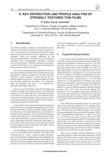
10 Materials Structure, vol. 5, no. 1 (1998)<br />
X- RAY DIFFRACTION LINE PROFILE ANALYSIS OF<br />
STRONGLY TEXTURED THIN FILMS<br />
P. Šutta 1 and Q. Jackuliak 2<br />
1 Department <strong>of</strong> Physics, Faculty <strong>of</strong> Logistics, Military Academy<br />
031 11 Liptovský Mikuláš, Slovak Republic<br />
2 Department <strong>of</strong> Technical Physics, Faculty <strong>of</strong> Electrical Engineering,<br />
University <strong>of</strong> ilina, 010 26 ilina, Slovak Republic<br />
1 Introduction<br />
Thin <strong>films</strong> <strong>of</strong> metallic conductors, semiconductors and insulators<br />
are the basic materials for modern electronic devices.<br />
For optimal device performance, these <strong>films</strong> should<br />
possess specific mechanical, electrical, magnetic or optical<br />
properties which are <strong>strongly</strong> influenced by the<br />
microstructural qualities <strong>of</strong> the <strong>films</strong> such as crystal<strong>line</strong> or<br />
amorphous state, crystallographic orientation, crystallite<br />
size, strain and stresses. Therefore, microstructural characterization<br />
<strong>of</strong> <strong>thin</strong> <strong>films</strong> is very important for the design and<br />
improvement <strong>of</strong> electronic devices 1.<br />
Due to their small dimensions perpendicular to the surface,<br />
the microstructure <strong>of</strong> <strong>thin</strong> <strong>films</strong> cannot be easily characterized<br />
by methods developed for the bulk materials.<br />
Therefore, various methods <strong>of</strong> surface physics are frequently<br />
applied to <strong>thin</strong> <strong>films</strong>. Among the analytical methods<br />
especially suitable for <strong>thin</strong> <strong>films</strong>, X-<strong>ray</strong> <strong>diffraction</strong><br />
plays an important role since it is nondestructive,<br />
noncontact and highly quantitative.<br />
However, due to the <strong>thin</strong>ness <strong>of</strong> the film the diffracting<br />
volume is normally very small resulting in weak diffracted<br />
intensities. On the other hand, due to preferred orientation<br />
<strong>of</strong> crystallites in a certain direction, some <strong>diffraction</strong> <strong>line</strong>s<br />
can reach very strong intensities so that in such case there is<br />
no problem to apply <strong>line</strong> <strong>pr<strong>of</strong>ile</strong> <strong>analysis</strong> to obtain the basic<br />
structural characteristics <strong>of</strong> <strong>thin</strong> <strong>films</strong>.<br />
In <strong>line</strong> <strong>pr<strong>of</strong>ile</strong> <strong>analysis</strong> mainly broadening and shape <strong>of</strong><br />
<strong>diffraction</strong> <strong>line</strong> are investigated. Broadening <strong>of</strong> X-<strong>ray</strong> <strong>diffraction</strong><br />
<strong>line</strong> <strong>pr<strong>of</strong>ile</strong>s is mainly caused by nonideal optics <strong>of</strong><br />
the instrument, wavelength dispersion and structural imperfections<br />
<strong>of</strong> the specimen. The structural <strong>line</strong> broadening<br />
is <strong>of</strong>ten subdivided into size broadening and strain broadening.<br />
Size broadening is caused by the finite size <strong>of</strong> domains<br />
diffracting essentially incoherently with respect to<br />
one another. On the other hand, strain broadening is caused<br />
by varying displacements <strong>of</strong> the atoms with respect to their<br />
reference-lattice positions [2].<br />
Line broadening is frequently characterized by means<br />
<strong>of</strong> one or two breadth measures (FWHM - full width at half<br />
maximum and β = Area/I o - integral breadth) and separation<br />
<strong>of</strong> size and strain contributions has been performed on<br />
this basis [3, 4]. More detailed <strong>analysis</strong> is possible by taking<br />
into account the complete shape <strong>of</strong> a <strong>line</strong> <strong>pr<strong>of</strong>ile</strong> by expressing<br />
it in terms <strong>of</strong> Fourier coefficients. Both breadth<br />
and Fourier methods gain in reliability when more than<br />
one order <strong>of</strong> reflection is used for a given set <strong>of</strong> lattice<br />
planes [5].<br />
2 Experimental procedure<br />
In our work, ceramic and metallic <strong>thin</strong> <strong>films</strong> deposited<br />
on single-crystal<strong>line</strong> silicon wafers by means <strong>of</strong> diode sputtering<br />
were investigated. In special cases Pd, Ti, Al, SiO 2<br />
and Al 2 O 3 buffer layers were also applied. A planar r.f.<br />
sputtering system Perkin Elmer 2400/8L was used. The<br />
sputtering chamber was always pumped down to 2x10 -5 Pa<br />
before admission <strong>of</strong> working gas (Ar or Ar/O 2 gas mixture<br />
99.999% in purity). Throughout the sputtering <strong>of</strong> Ag, Pd,<br />
Pt, Al, ZnO and Al 2 O 3 targets (each 203 mm in diameter<br />
and 99.95% in purity) a gas pressure <strong>of</strong> 1.3 Pa was kept<br />
constant [6, 7]. The temperature <strong>of</strong> substrate was mostly<br />
kept at room temperature. In special cases the temperature<br />
<strong>of</strong> substrate was kept at 300 o Corat600 o C. The effects <strong>of</strong><br />
different r.f. powers, different substrates, different metallic<br />
materials with a FCC cubic unit cell and different film<br />
thicknesses were investigated. Furthermore, different ratios<br />
<strong>of</strong> Ar/O 2 gas mixture in case <strong>of</strong> ZnO <strong>films</strong> as well as the<br />
cyclic sputtering and ion etching <strong>of</strong> <strong>films</strong> were applied [8,<br />
9]. The general characterization <strong>of</strong> sputtered <strong>films</strong> is listed<br />
in Table 1.<br />
X-<strong>ray</strong> <strong>diffraction</strong> <strong>line</strong> <strong>pr<strong>of</strong>ile</strong> <strong>analysis</strong> was used to determine<br />
microstructural properties <strong>of</strong> investigated <strong>films</strong>.<br />
First, preliminary <strong>diffraction</strong> patterns was recorded on the<br />
film. After that, the X-<strong>ray</strong> <strong>diffraction</strong> data were collected<br />
by using an automatic X-<strong>ray</strong> powder diffractometer URD-6<br />
with a Bragg-Brentano goniometer. A copper X-<strong>ray</strong> tube<br />
(λ= 0.154178 nm) was used. Ceramic Al 2 O 3 from NIST<br />
was used as an instrumental standard. The intensities <strong>of</strong> <strong>diffraction</strong><br />
<strong>line</strong>s were collected with a constant step <strong>of</strong> 0.02<br />
deg <strong>of</strong> 2-theta and with a constant counting time <strong>of</strong> 20 seconds<br />
at each step. In order to appreciate degree <strong>of</strong> preferred<br />
orientation, the omega-scans <strong>of</strong> the most intensive <strong>diffraction</strong><br />
<strong>line</strong>s for each material were also recorded.<br />
From several available methods appropriate for the<br />
<strong>line</strong> <strong>pr<strong>of</strong>ile</strong> <strong>analysis</strong> a single-<strong>line</strong> method based on a Voigt<br />
function [3] which is more versatile and powerful from the<br />
practical point <strong>of</strong> view was used to determine size-strain<br />
parameters (microstrains and crystallite sizes) <strong>of</strong> investigated<br />
<strong>thin</strong> <strong>films</strong> 4]. Because no monochromator was used,<br />
© Krystalografická spoleènost
X- RAY DIFFRACTION LINE PROFILE ANALYSIS OF STRONGLY TEXTURED THIN FILMS 11<br />
Table 1. Characterization <strong>of</strong> investigated <strong>thin</strong> <strong>films</strong><br />
Sample<br />
(<strong>thin</strong> film)<br />
Special<br />
conditions<br />
Substrate<br />
(configuration)<br />
R.f. Power [W]<br />
Thickness [nm]<br />
Substrate temperature<br />
[ O C]<br />
ZnO 1 Ar+O 2 (25/75) Al/SiO 2 /Si 500 1000 room<br />
ZnO 2 Ar+O 2 (25/75) SiO 2 /Si 500 1000 room<br />
ZnO 3 5x etch Al/SiO 2 /Si 500 1000 room<br />
ZnO 4 5x etch SiO 2 /Si 500 1000 room<br />
ZnO 5 Ar+O 2 (60/40) Al/SiO 2 /Si 500 1000 room<br />
ZnO 6 Ar+O 2 (60/40) SiO 2 /Si 500 1000 room<br />
Zn x O y 1 Multilayers Al x O y /SiO 2 /Si 500 250 room<br />
Zn x O y 2 Multilayers Al x O y /SiO 2 /Si 500 250 300<br />
Zn x O y 3 Multilayers Al x O y /SiO 2 /Si 500 250 600<br />
Ag 1 Ar Pd/Ti/SiO 2 /Si 250 1000 room<br />
Ag 2 Ar Pd/Ti/SiO 2 /Si 500 1000 room<br />
Ag 3 Ar Pd/Ti/SiO 2 /Si 800 1000 room<br />
Ag 4 Ar SiO 2 /Si 500 1000 room<br />
Ag 5 Ar Si [100] 500 1000 room<br />
Pd Ar Si [100] 500 1100 room<br />
Pt Ar Si [100] 500 1000 room<br />
the K α2 <strong>line</strong> had to be removed by a Rachinger method (in<br />
case <strong>of</strong> broad <strong>line</strong>s <strong>of</strong> ZnO and Pt <strong>films</strong>) and by a graphic<br />
method 10, 11] modified for a processing on a personal<br />
computer (in case <strong>of</strong> narrow <strong>line</strong>s <strong>of</strong> metallic Ag and Pd<br />
<strong>films</strong>).<br />
3 Results and Discussion<br />
Because Zinc Oxide has a hexagonal close-packed<br />
wurtzite structure, polycrystal<strong>line</strong> <strong>thin</strong> <strong>films</strong> prepared by<br />
different techniques have usually preferential orientation<br />
<strong>of</strong> their grains in the [001] direction perpendicular to the<br />
substrate, <strong>strongly</strong> depending on the deposition conditions<br />
in the deposition unit.<br />
Diffraction patterns preliminary recorded on the film<br />
indicated that all investigated <strong>films</strong> were polycrystal<strong>line</strong>.<br />
Almost in all cases, a very strong preferred orientation <strong>of</strong><br />
crystallites perpendicular to the substrate, depending on the<br />
material and on the special conditions in the course <strong>of</strong> deposition,<br />
was observed. In case <strong>of</strong> zinc oxide <strong>films</strong> the preferred<br />
orientation is mainly in the [001] and [110]<br />
directions and in case <strong>of</strong> metallic <strong>films</strong> (Ag, Pd, Pt) it is in<br />
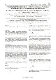
the [111] direction (See part <strong>of</strong> ZnO X-<strong>ray</strong> <strong>diffraction</strong> patterns<br />
presented in Figures 1, 2, 3 and 4).<br />
Figure 1. Influence <strong>of</strong> aluminium buffer layer on preferred orientation<br />
<strong>of</strong> ZnO film (Ar/O 2 =25/75 %)<br />
Figure 2. Influence <strong>of</strong> cyclic sputtering and ion etching <strong>of</strong> <strong>films</strong><br />
on preferred orientation <strong>of</strong> ZnO <strong>films</strong> (Ar/O 2 = 25/75 %)<br />
© Krystalografická spoleènost
12 X- RAY DIFFRACTION LINE PROFILE ANALYSIS OF STRONGLY TEXTURED THIN FILMS<br />
Sample<br />
(<strong>thin</strong> film)<br />
Table 2 Data <strong>of</strong> investigated <strong>thin</strong> <strong>films</strong> obtained from X-<strong>ray</strong> <strong>diffraction</strong><br />
Investigated <strong>line</strong><br />
Line position<br />
Intensity <strong>of</strong><br />
K α1 [cps]<br />
FWHM [deg]<br />
ZnO 1 002 34.184 436 0.4825 282.8<br />
ZnO 2 002 34.205 1467 0.5568 1052<br />
ZnO 3 110 56.265 101 0.9765 119.4<br />
ZnO 4 110 56.324 279 1.0537 359.4<br />
ZnO 5 002 34.216 1664 0.4591 1016<br />
ZnO 6 002 34.027 2445 0.7335 2218<br />
Zn x O y 1 002 34.265 5.9 0.4453 3.3<br />
Zn x O y 2 002 34.379 32.47 0.5799 24.4<br />
Zn x O y 3 002 34.372 724.4 0.4254 365.7<br />
Ag 1 111 38.128 2428 0.0607 201.0<br />
Ag 2 111 38.109 4345 0.0559 320.1<br />
Ag 3 111 38.109 8781 0.0594 686.9<br />
Ag 4 111 38.103 1980 0.0550 154.8<br />
Ag 5 111 38.142 3527 0.0682 336.2<br />
Pd 111 40.197 1548 0.0790 172.4<br />
Pt 111 39.776 2.2277 0.2076 6272<br />
Integrated<br />
intensity [deg/s]<br />
Sample<br />
(<strong>thin</strong> film)<br />
Investigated <strong>line</strong><br />
Table 3 Size-strain data <strong>of</strong> investigated <strong>thin</strong> <strong>films</strong><br />
Integral breadth<br />
[deg] β<br />
Shape factor<br />
φ=FWHM/β<br />
Microstrains<br />
x10 3<br />
ZnO 1 002 0.6493 0.7432 4.5 26<br />
ZnO 2 002 0.7171 07764 5.9 28<br />
ZnO 3 110 1.1818 0.8263 6.9 25<br />
ZnO 4 110 1.2897 0.8170 7.3 21<br />
ZnO 5 002 0.6104 0.7522 4.5 29<br />
ZnO 6 002 0.9070 0.8087 8.6 27<br />
Zn x O y 2 002 0.7462 0.7772 6.2 27<br />
Zn x O y 3 002 0.548 0.8427 5.3 97<br />
Ag 1 111 0.0828 0.7329 0.24 320<br />
Ag 2 111 0.0737 0.7591 0.27 561<br />
Ag 3 111 0.0782 0.7593 0.32 479<br />
Ag 4 111 0.0782 0.7493 0.21 494<br />
Ag 5 111 0.0952 0.7166 0.27 218<br />
Pd 111 0.1115 0.7084 0.28 158<br />
Crystallite size<br />
D [nm]<br />
© Krystalografická spoleènost
X- RAY DIFFRACTION LINE PROFILE ANALYSIS OF STRONGLY TEXTURED THIN FILMS 13<br />
In case <strong>of</strong> continual sputtering there is a [001] preferred<br />
orientation <strong>of</strong> crystallites perpendicular to the substrate.<br />
Cyclic sputtering and ion etching <strong>of</strong> <strong>films</strong> in the<br />
course <strong>of</strong> deposition with 75% <strong>of</strong> O 2 content in the Ar/O 2<br />
gas mixture resulted in [110] preferred orientation <strong>of</strong> ZnO<br />
grains perpendicular to the substrate. After cyclic sputtering<br />
and ion etching <strong>of</strong> <strong>films</strong> with 40% O 2 content in the<br />
Ar/O 2 gas mixture a very strong preferred orientation <strong>of</strong><br />
ZnO crystallites in the [001] direction perpendicular to the<br />
substrate was observed again.<br />
The aluminium conductive layer resulted in a decrease<br />
<strong>of</strong> preferred orientation <strong>of</strong> ZnO crystallites (Figures 1 and<br />
3) as well as decrease <strong>of</strong> lattice imperfections, which can be<br />
observed in decreasing <strong>of</strong> microdeformations. Furthermore,<br />
in all cases <strong>of</strong> ZnO <strong>films</strong> a considerable shift <strong>of</strong> (002)<br />
and (110) <strong>diffraction</strong> <strong>line</strong>s towards the less <strong>diffraction</strong> angles<br />
was observed (See Table 2). Regular positions <strong>of</strong> (002)<br />
and (110) ZnO <strong>line</strong>s according to JCPDS standard are<br />
34.44 and 56.55 deg respectively. This <strong>line</strong> displacement is<br />
accompanied with the lattice strains which are present in<br />
the ZnO <strong>films</strong> due to lattice mismatch between the layer<br />
and substrate and due to the low-energy ion bombardment<br />
<strong>of</strong> <strong>films</strong>.<br />
The texture evolution depending on the substrate temperature<br />
during the deposition can be demonstrated on<br />
Zn x O y /Al x O y multilayered structures prepared as sensitive<br />
layers for UV radiation. When substrate temperature during<br />
the deposition was kept below 300 o C, a part <strong>of</strong> amorphous<br />
phase was also observed. Much better preferred orientation<br />
was observed when substrate temperature was<br />
kept on 600 o C (See Figure 4 and Table 2).<br />
The most expressive preferred orientation <strong>of</strong> crystallites<br />
in the [111] direction perpendicular to the substrate<br />
was observed in case <strong>of</strong> metallic Ag, Pd and Pt <strong>films</strong>. These<br />
<strong>films</strong> are suitable materials for chemical and bio-chemical<br />
sensors as catalytic metal layers or as reference electrodes.<br />
XRD-scans <strong>of</strong> (111) <strong>line</strong>s are demonstrated in Figures 5, 6<br />
and 7.<br />
Figure 3. Influence <strong>of</strong> O 2 content in gas mixture on preferred orientation<br />
<strong>of</strong> ZnO film (Ar/O 2 =60/40 %)<br />
Figure 5. XRD-scan for (111) <strong>line</strong> <strong>of</strong> Ag film deposited on single<br />
crystal<strong>line</strong> Si [100] substrate<br />
Figure 4. Influence <strong>of</strong> substrate temperature on preferred orientation<br />
<strong>of</strong> Zn x O y /Al x O y multilayered structures (Ar/O 2 = 25/75 %)<br />
Figure 6. XRD-scan for (111) <strong>line</strong> <strong>of</strong> Pd film deposited on single<br />
crystal<strong>line</strong> Si [100] substrate<br />
In this case, only (111) <strong>line</strong> and its second order were<br />
observed. Degree <strong>of</strong> preferred orientation can be partially<br />
appreciated by the width <strong>of</strong> the omega-scans <strong>of</strong> (111) <strong>line</strong>s.<br />
The widths <strong>of</strong> the omega-scans for (111) <strong>line</strong>s <strong>of</strong> investigated<br />
Ag and Pt <strong>films</strong> are about 3.3-3.7 deg. For Pd film it<br />
is about 6.4 deg. Higher r.f. power applied in the sputtering<br />
unit resulted in a higher degree <strong>of</strong> preferred orientation <strong>of</strong><br />
crystallites.<br />
4 Conclusions<br />
Our experiments indicated that the X-<strong>ray</strong> <strong>diffraction</strong><br />
<strong>line</strong> <strong>pr<strong>of</strong>ile</strong> <strong>analysis</strong> carried out on a common X-<strong>ray</strong> powder<br />
diffractometer can be successfully used when investigating<br />
the microstructural properties <strong>of</strong> <strong>strongly</strong> <strong>textured</strong> <strong>thin</strong><br />
© Krystalografická spoleènost
14 X- RAY DIFFRACTION LINE PROFILE ANALYSIS OF STRONGLY TEXTURED THIN FILMS<br />
References<br />
Figure 7. XRD-scan for (111) <strong>line</strong> <strong>of</strong> Pt film deposited on single<br />
crystal<strong>line</strong> Si [100] substrate<br />
Figure 8. Omega-scans for (111) <strong>line</strong>s <strong>of</strong> Pt and Ag <strong>films</strong> deposited<br />
on single crystal<strong>line</strong> Si [100] substrate<br />
<strong>films</strong>. The <strong>analysis</strong> is successful also in case when the film<br />
thickness is more less than one micrometer. More attention<br />
has to be paid to the narrow <strong>line</strong>s because in case <strong>of</strong> their<br />
approximation by a non-appropriate <strong>pr<strong>of</strong>ile</strong> the results can<br />
be over- or underestimated.<br />
Acknowledgements<br />
The authors would like to thank Pr<strong>of</strong>. V. Tvaro ek and<br />
Dr. I. Novotný from Slovak University <strong>of</strong> Technology<br />
Bratislava for the preparing <strong>of</strong> samples and Pr<strong>of</strong>. J. Fiala<br />
from ŠKODA Research Ltd. Plzeò, for the recording <strong>of</strong> preliminary<br />
<strong>diffraction</strong> patterns on the film and for valuable<br />
discussions during the preparation <strong>of</strong> the paper. This work<br />
was supported by grant No. IC15-CT96-0804.<br />
1. A. Segmüller, I.C. Noyan and V.S. Speriosu, X-<strong>ray</strong> Diffraction<br />
Studies <strong>of</strong> Thin Films and Multilayer Structures, Prog.<br />
Crystal Growth and Charact. 18, (1989) pp 21-66<br />
2. J.G.M. Van Berkum, J.G.M., A.C. Vermeulen, R. Delhez,<br />
Th.H. De Keijser, and E.J. Mittemeijer. Applicabilities <strong>of</strong><br />
the Warren-Averbach Analysis and an Alternative Analysis<br />
for Separation <strong>of</strong> Size and Strain Broadening, J. Appl.<br />
Cryst. 27, (1994) pp. 345-357<br />
3. J.I. Langford. A Rapid Method for Analysing the Breadths<br />
<strong>of</strong> Diffraction and Spectral Lines using the Voigt Function,<br />
J. Appl. Cryst. 11, (1978) pp 10-14<br />
4. R. Delhez, Th.H. De Keijser and E.J. Mittemeijer. Determination<br />
<strong>of</strong> Crystallite Size and Lattice Distortions through<br />
X-<strong>ray</strong> Diffraction Line Pr<strong>of</strong>ile Analysis, Fresenius Z. Anal.<br />
Chem. 312, (1982) pp 1-16<br />
5 D. Balzar, and H. Ledbetter. Voigt-Function Modeling in<br />
Fourier Analysis <strong>of</strong> Size- and Strain-Broadened X-<strong>ray</strong> Diffraction<br />
Peaks, J. Appl. Cryst. 26, (1993) pp. 97-103<br />
6. V. Tvaro ek et al Sensors and Actuators B, 18-19,(1994)<br />
pp. 597-602<br />
7. V. Tvaro ek. Microsystem Technology in Biosensors. D.P.<br />
Nikolelis et al (eds.), Biosensors for Direct Monitoring <strong>of</strong><br />
Environmental Pollutants in Field, 351-371, Kluwer Academic<br />
Publishers. Printed in the Netherlands. (1998)<br />
8. I. Novotný, P. Šutta, F. Mika and V. Tvaro ek. Piezoelectric<br />
ZnO Thin Films Prepared by Cyclic Sputtering and Etching<br />
Technology, In: Proc. <strong>of</strong> the 20th International Conference<br />
on Microelectronics MIEL95, Vol.1, held in Niš, Serbia,<br />
12-14 September 1995 pp. 65-68<br />
9. P. Šutta. et al X-<strong>ray</strong> Diffraction Analysis and Optical Properties<br />
<strong>of</strong> ZnO Thin Films Prepared by Cyclic Sputtering<br />
and Etching Technique, In: Proc. <strong>of</strong> the international conference<br />
ASDAM’96, held in October 22-26, 1996,<br />
Smolenice, Slovakia<br />
10. Q. Jackuliak, and P. Šutta, Refinement <strong>of</strong> Method for Calculation<br />
<strong>of</strong> K 1 and K 2 Components <strong>of</strong> Diffraction Line, In:<br />
Materials Structure in Chemistry, Biology, Physics and<br />
Technology, Vol. 3, (1996) No. 3, pp. 267-269<br />
11 I.B. Borovskij, Fizièeskije osnovy rentgenospektra¾nych<br />
issledovanij, Izdate¾stvo Moskovskogo universiteta,<br />
Moskva 1956<br />
© Krystalografická spoleènost