SB 9 Mini Variometer w. Emergency Battery - ILEC GmbH
SB 9 Mini Variometer w. Emergency Battery - ILEC GmbH
SB 9 Mini Variometer w. Emergency Battery - ILEC GmbH

Create successful ePaper yourself
Turn your PDF publications into a flip-book with our unique Google optimized e-Paper software.
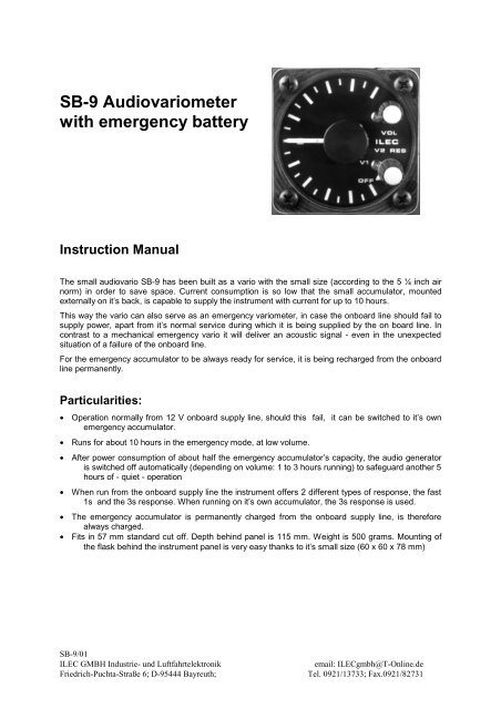
<strong>SB</strong>-9 Audiovariometer<br />
with emergency battery<br />
Instruction Manual<br />
The small audiovario <strong>SB</strong>-9 has been built as a vario with the small size (according to the 5 ¼ inch air<br />
norm) in order to save space. Current consumption is so low that the small accumulator, mounted<br />
externally on it’s back, is capable to supply the instrument with current for up to 10 hours.<br />
This way the vario can also serve as an emergency variometer, in case the onboard line should fail to<br />
supply power, apart from it’s normal service during which it is being supplied by the on board line. In<br />
contrast to a mechanical emergency vario it will deliver an acoustic signal - even in the unexpected<br />
situation of a failure of the onboard line.<br />
For the emergency accumulator to be always ready for service, it is being recharged from the onboard<br />
line permanently.<br />
Particularities:<br />
• Operation normally from 12 V onboard supply line, should this fail, it can be switched to it’s own<br />
emergency accumulator.<br />
• Runs for about 10 hours in the emergency mode, at low volume.<br />
• After power consumption of about half the emergency accumulator’s capacity, the audio generator<br />
is switched off automatically (depending on volume: 1 to 3 hours running) to safeguard another 5<br />
hours of - quiet - operation<br />
• When run from the onboard supply line the instrument offers 2 different types of response, the fast<br />
1s and the 3s response. When running on it’s own accumulator, the 3s response is used.<br />
• The emergency accumulator is permanently charged from the onboard supply line, is therefore<br />
always charged.<br />
• Fits in 57 mm standard cut off. Depth behind panel is 115 mm. Weight is 500 grams. Mounting of<br />
the flask behind the instrument panel is very easy thanks to it’s small size (60 x 60 x 78 mm)<br />
<strong>SB</strong>-9/01<br />
<strong>ILEC</strong> GMBH Industrie- und Luftfahrtelektronik<br />
Friedrich-Puchta-Straße 6; D-95444 Bayreuth;<br />
email: <strong>ILEC</strong>gmbh@T-Online.de<br />
Tel. 0921/13733; Fax.0921/82731
Principle of measurement<br />
The transducer is a thermal flow measurement device using thermistors at constant temperature,<br />
developed by <strong>ILEC</strong>. It offers an excellent stability of zero output, a very short response time of 5<br />
milliseconds, and strong independence of calibration of changes in temperature of the instrument. It<br />
ensures the instruments famous high precision.<br />
Signal conditioning<br />
The raw variometer signal coming from the transducer is fed to two different electronic filters in<br />
parallel. With the help of the V1 / V2 - filter switch, the display (visual and acoustic) can alternatively be<br />
switched to one of the following filters:<br />
V1: 3-sec-filter: first order filter with a response equivalent a good moving vane type<br />
V2: 1-sec-filter: second order filter with a fast, however strongly damped response. In the emergency<br />
case only the 3-sec-filter is available.<br />
Audio generator<br />
Visual meter indication is important but the audio provides the heart of the <strong>SB</strong>-9. The base frequency<br />
of the audio signal increases exponentially with vertical speed. It´s base pitch is modulated by a slow<br />
frequency which varies with the rate of climb. At zero climb this frequency is reduced to zero producing<br />
a continuous tone. In sink the modulation frequency is constant at 1 per second. This double tone <strong>ILEC</strong><br />
audio is a delight to listen to, providing instant information on rate of climb or sink between +/- 30 kts.<br />
This wide range provides accurate information in the weakest and strongest thermals.<br />
Altitude error<br />
The calibration factor of the variometer depends on air density and therefore on altitude. When<br />
measuring the actual vertical speed, the indicated value decreases at 5% per 1000 meters increase in<br />
altitude. In the altitude range from 200 to 2200 m NN the altitude error remains within +/- 5%, at 1200<br />
m NN , the calibration altitude, the error is zero.<br />
Technical Data:<br />
Supply Voltage: 10 to 15 Volts<br />
Consumption: 10mA up to 30 mA, depending on audio volume<br />
Dimensions: 61 x 62 x 115mm (fits in 57mm standard cutout)<br />
Weight:<br />
0.5 kg<br />
Temp. Range: -20 to + 60 deg C<br />
Measurement: +/- 30 kts<br />
Audio: +/- 30 kts<br />
Meter: +/- 10 kts<br />
Zero Accuracy: +/- 0.3 kts from -20 to + 50 deg C<br />
Calibration: Measurement: +/- 2%<br />
Meters: +/- 3%<br />
Altitude: 0 to 45000ft<br />
Installation<br />
2
When choosing the place where the instrument is to be installed the following point should be taken<br />
into account:<br />
• Since the variometer is read rather frequently, the instrument should be placed at the upper rim of<br />
the instrument panel.<br />
• If a compass is installed in the panel, all other non magnetic instruments should be grouped around<br />
it (altimeter, air speed indicator, moving vane variometer), all electrical instruments at a distance<br />
of at least 10 to 15 cm. The same applies to a compass mounted on the cover over the panel:<br />
the speaker at the rear end of the instrument may disturb in this case.<br />
• During transport, take off and landing, the glider will be submitted to rather severe shocks which<br />
should be kept off all instruments. Contrary to a widespread opinion, the best suspension is the one<br />
that will link all instruments to the primary structure of the fuselage in the most r i g i d way. For<br />
this reason instrument panels should be designed for maximum rigidity and linked to the fuselage in<br />
the most rigid way.<br />
Panel cutout:<br />
Figure 1 shows the dimension of the 80-mm- and 57-mm-openings to be machined in the panel. If they<br />
are not yet there, work with precision. It must be possible to insert the instrument and in particular the<br />
bolts freely without any jamming, otherwise the nut inserts may be damaged. Fixing bolts delivered are<br />
M4x10, non magnetic, black, Phillips-head 3.<br />
Figure 1: Opening in the instrument panel<br />
Dimensions in mm, dimensions in brackets for 57-mm-cutout<br />
<strong>Variometer</strong> flask:<br />
• The flask is being mounted behind the instrument panel. The flexible silicon connecting tube is<br />
delivered with the instrument, it may be shortened at will.<br />
Electrical connection:<br />
• Connect the blue wire to battery ground, the red wire to battery plus 12VDC<br />
Pneumatic installation:<br />
• Connect the total energy pressure to the large nipple, the variometer flask to the small one.<br />
Basic operation<br />
<strong>SB</strong>-9/01<br />
<strong>ILEC</strong> GMBH Industrie- und Luftfahrtelektronik<br />
Friedrich-Puchta-Straße 6; D-95444 Bayreuth;<br />
email: <strong>ILEC</strong>gmbh@T-Online.de<br />
Tel. 0921/13733; Fax.0921/82731
Upper button: Volume control.<br />
Lower button: Select switch position 1: OFF<br />
position 2: V1 normal 3-sec-variometer<br />
position 3: V2 fast 1-sec-variometer<br />
position 4: RES normal 3-sec-variometer<br />
emergency battery in use<br />
Charging the emergency battery:<br />
The emergency accumulator is permanently being recharged from the onboard supply. The position of<br />
the select switch is of no importance. But for this instance the main power supply must be switched on,<br />
the <strong>SB</strong>-9 must be connected to the onboard battery.<br />
Operation with emergency battery:<br />
The automatic supervisor cicuit will switch off the <strong>SB</strong>-9 upon the supply voltage becoming too low. This<br />
happens in 3 steps:<br />
When operated with audio signal, the running time depends on volume setting. With medium volume<br />
setting, there will be about 3 hours operation with audio signal, afterwards about 5 hours without audio.<br />
With full audio signal you will have about 1 hour operation with audio and afterwards 5 hours without.<br />
The <strong>SB</strong>-9 operates about 10 hours without audio signal in the RES setting. The <strong>SB</strong>-9 is switched off<br />
automatically when the emergency battery voltage falls below 7.7V, to prevent overdischarging and<br />
damaging this accumulator.<br />
Maintenance<br />
<strong>SB</strong>-9 adjustments<br />
The audio basic and modulation frequency can be adjusted to personal preference by two<br />
potentiometers. These are accessible from the top after removing the instruments case.<br />
The zero of the variometer signal can be adjusted by a - non laquered - potentiometer accessible<br />
from the bottom side. Do not remove the laquered potentiometer.<br />
<strong>Emergency</strong> accumulator<br />
The emergency battery is a NiCd accumulator and should be renewed after 5 years. Only use a type<br />
like VARTA TR 7/8 for this purpose.<br />
CAUTION:<br />
Never use non rechargeable primary batteries, they may blow up when being<br />
charged.<br />
The lifetime of this accumulator will be extented, when being discharged twice a year. Therefore we<br />
recommend the <strong>SB</strong>-9 to be switched to the emergency mode (RES) for at least 10 hours, main battery<br />
off, to discharge ist accumulator. Don´t forget charging afterwards.<br />
4