ILEC FINAL GLIDE COMPUTER GPS - ASR - ILEC GmbH
ILEC FINAL GLIDE COMPUTER GPS - ASR - ILEC GmbH
ILEC FINAL GLIDE COMPUTER GPS - ASR - ILEC GmbH

Create successful ePaper yourself
Turn your PDF publications into a flip-book with our unique Google optimized e-Paper software.
1<br />
<strong>ILEC</strong> <strong>FINAL</strong> <strong>GLIDE</strong> <strong>COMPUTER</strong> <strong>GPS</strong> - <strong>ASR</strong><br />
1. About this manual<br />
This manual should be added to the accompanying manual of the SB-8. That one should be<br />
held in the file of the aircraft into which the whole system is installed. This way it will be available<br />
to every pilot who wants to know how the system works and how to use it.<br />
The general chapters of the SB-8 manual about installation, cabling, etc. have of course their<br />
validity also for this instrument.<br />
This manual is regularly updated. It applies to instruments with the serial numbers defined<br />
below, at any rate to the instrument it has been delivered with.<br />
This instrument applies to instruments of the <strong>GPS</strong>-<strong>ASR</strong> model.<br />
State : February 1994<br />
List of contents<br />
1. About this manual<br />
2. Description of the System<br />
1. Functions<br />
2. Mode of Action<br />
3. Accuracy<br />
3. Operating Instructions<br />
1. Adjustment of Safety Altitude<br />
2. Operation en route<br />
3. Operation en route with <strong>GPS</strong>-data<br />
4. Operation en route without <strong>GPS</strong>-data<br />
4. Installation and Maintenance<br />
1. Mechanical Installation<br />
2. Electrical Connections<br />
3. Maintenance and Functional Checks<br />
5. Programming
2. Description of the System<br />
2<br />
2.1. Functions<br />
The <strong>GPS</strong>-<strong>ASR</strong> serves as final glide computer in combination to the SB-8 vario-speed command<br />
computer. The indicated altitude of approach is always the altitude required for the residual<br />
distance. There are two from each other independent functions to choose from :<br />
a) Final glide computer without <strong>GPS</strong> :<br />
Manual input of distance to the turnpoint or goalpoint. The wind component is flown on a<br />
measuring route (adaptive wind-computer) and set at the wind knob. Display of residual<br />
distance as well as required altitude of approach.<br />
b) With <strong>GPS</strong>-Information : Automatic takeover of the <strong>GPS</strong>-distance display and calculation of<br />
the wind component. Display of residual distance as well as required altitude of approach.<br />
2.2. Mode of Action<br />
The <strong>GPS</strong>-<strong>ASR</strong> uses the following information from the SB-8 : dynamic pressure, McCready -<br />
value, wing loading, polar selected, mode (vario / speed command). At the <strong>GPS</strong>-<strong>ASR</strong> itself are<br />
to be set : wind component, distance (without <strong>GPS</strong>), function (final glide computer with / without<br />
<strong>GPS</strong>-coupling). With the <strong>GPS</strong>-<strong>ASR</strong> itself the altitude is measured (pressure) to convert the<br />
dynamic pressure into the required velocities.<br />
The distance covered with reference to ground is continuously computed on the basis of<br />
true air-speed (TAS), wind component, time and mode (vario / speed command) in the mode<br />
glide computer without <strong>GPS</strong> (AR). In the mode <strong>GPS</strong> the distance from the <strong>GPS</strong> is taken over.<br />
The required altitude of approach is computed on the basis of distance to goal, the optimum<br />
glide speed in vertical calm air and the safety altitude in which the goal is supposed to be<br />
reached ( FA = Final Altitude ).<br />
ATTENTION: One must fly at the speed given by the speed command of the SB-8.<br />
The (adaptive) wind component measures the time interval during wind has had an influence.<br />
Starting for that is the moment of the last actuation at the distance knob at the beginning of the<br />
measuring route. The computer takes the momentary set wind component for each one of its<br />
calculations. The drift distance calculated (which is being attributed to wind alone) is being<br />
added to the flight distance with reference to air (which it has counted up all the time). The sum<br />
of both routes is the distance displayed. If now the distance displayed coincides with the real<br />
distance covered on ground, then the wind was set correctly. Otherwise the adjustment at the<br />
wind knob must be changed until the length of the measuring route coincides with the display.<br />
This will then be the correct wind component for the calculation of the altitude of approach and<br />
the flight.<br />
By "inverse calculation" any further parameter can be determined. The parameter to be<br />
computed (McCready - value, e.g. which enables to reach an arbitrary goal over a residual<br />
distance, and from a given altitude). To do that, one keeps turning the relevant knob (for<br />
example the McCready knob) until the result is the one sought. Now all the set parameters are<br />
correct. (By playing with the different knobs one will learn quickly to assess the influence of the<br />
different variables on the possible distance or the glide ratio programmed into the instrument.)
2.3. Accuracy<br />
3<br />
a) Distance Measurement<br />
The total error for measuring distances is the sum of errors of the measuring pressures<br />
(normally less than 2%), plus the error of the speed transducer in the SB-8, plus the calculation<br />
error of the <strong>ASR</strong> itself. The calculation accuracy of the <strong>ASR</strong> is better than 2% for altitudes up to<br />
18.000 feet, above this altitude it will slowly decrease to the upper operating altitude of <strong>GPS</strong>-<br />
<strong>ASR</strong> at 33.000 feet. The velocity for the <strong>ASR</strong> to work properly is in the range from 30 to 150 kts.<br />
In day to day flying the above stated accuracy willnot be met for the following reasons :<br />
* Flight path has not been straight<br />
* Mode has not been set correctly (flight on path in position vario)<br />
* The wind component was not set correctly (it varies with altitude and time).<br />
According to specialist pilots, one will have to reckon with an error from 5 - 10% in real life.<br />
b) Altitude Computation<br />
The computational accuracy depends on a great number of variables. Normally it is in the order<br />
of 1%. Since for great values of altitude, or distance which is based on the computation, the 1%error<br />
can be larger than one digit of the display, therefore this latter one may jitter. This happens<br />
in particular if the wind computer runs very long.<br />
c) Polars<br />
Some polars published are not necessarily made to honour scientific truth, but rather to promote<br />
sales. Some are really honest curves. The polars that were used for the programming of this<br />
instrument, were all subjected to scrutiny. By principle only measured polars have been used.<br />
Since the measurements were done with clean aircraft, we have generally "worsened" the polars<br />
by 5%.<br />
ATTENTION : This does not constitute a reserve, it only takes care of the experience. (A<br />
reserve, for example, can be considered through the approach distance, or by adjusting the<br />
McCready - value to at least 2 kts.<br />
Bugged polars are "worsened" the same way as normal polars, only stronger, depending on the<br />
type of plane in general by 20 - 30%. Where the polar in question could not be approximated<br />
exactly by a polynominal of the second order, slow flying has been favoured in the process.<br />
3. Operating Instructions<br />
The distance and final glide computer <strong>GPS</strong>-<strong>ASR</strong> is turned on and off with the main switch at the<br />
SB-8 vario.<br />
3.1. Setting of Safety Altitude FA (Final Altitude)<br />
If on moves the function switch (AR - <strong>GPS</strong> - W/A) to the right and holds it there, the safety<br />
altitude (FA) can be set with the input-rotary knob.<br />
So two hands are needed for the adjustment - this adjustment should be done on ground before<br />
the flight. An accidental change is being excluded by the "two-hand-operation". The safety<br />
altitude is automatically being added to the altitude required by the air route. To carry out a<br />
decent final approach with a safe landing at the arrival at the air field, a reseve of at least 300 -<br />
500 feet ( 3H - 5H ) should be entered.<br />
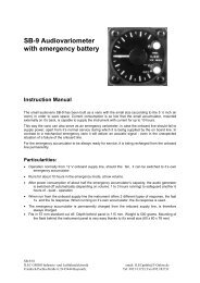
3.2. Operation en Route
The function switch is either switched in position AR (when operating without <strong>GPS</strong>) or in position<br />
<strong>GPS</strong>. In the right side of the display window always the distance to the goal- or turnpoint is<br />
indicated; in the left side of the display window the required altitude to that (inclusive of the safety<br />
altitude FA). The smallest dispresal of the distance display is 0.1nm and 100 feet ( 1H ) for the<br />
altitude display. A display of 30H, e.g., means that 3000 feet are necessary. If one sets the<br />
altimeter on QFE, the altitude displays must coincide. The computer indicates the ABSOLUTE<br />
ALTITUDE one should have at the moment to reach the choosen goal at the final altitude under<br />
the condition of CALM AIR and under the keeping of all other prerequisites (distance, wing<br />
loading, polars, wind component, mainly however, the McCready - value). In real life these<br />
prerequisites will rarely be fulfilled, therefore an approach must be ACTIVE SUPERVISED. (This<br />
doesn´t have anything to do with the computer). The influence of further parameters becomes<br />
clearly, if one shifts these.<br />
On the SB-8 vario the following adjustments are done :<br />
a) Normal polars PN or bugged polars PX<br />
b) wing loading (this has great influence during headwind)<br />
c) McCready - value<br />
If one reckons with an area of sinking air during the final glide, then the glide should always be<br />
started with a MC adjustment larger than 0 kts. During approachment to the goal this adjustment<br />
can be reduced. If one reckons with an area of even up- and downdrafts, the approach can also<br />
be begun with a MC adjustment of 0 kts and then later one can try to collect reserve on the way.<br />
However, this is riskier and demands a conscientiuous keeping of the speed command.<br />
At the final glide computer <strong>GPS</strong>-<strong>ASR</strong> the wind component is set with the potentimeter on the left<br />
hand side of the instrument. The wind scale has a subdivision into 5 kts. and has a range from -<br />
30 kts. headwind (opposite pointed arrows) to + 30 kts. tailwind (even pointed arrows). The<br />
determination of the wind component on course can only lead to a correct result, as long as one<br />
really flies on course. The calculation of wind in the <strong>GPS</strong> - mode is different from the AR - mode<br />
and will be explained further down.<br />
3.3. Operation en Route with <strong>GPS</strong> - data<br />
The function switch is in position <strong>GPS</strong>. As long as no <strong>GPS</strong> - data is received, the display will<br />
indicate "<strong>GPS</strong> OFF". After the beginning of the automatic data transfer the same distance to the<br />
turn- or goalpoint as on the <strong>GPS</strong>-receiver will appear in the right side of the display window. In<br />
the left side the required altitude for this air route will be displayed. This altitude still depends on<br />
the parameters named above (polars, McCready-value, wing loading and the wind component).<br />
The determination of the wind component takes place automatically due to comparison of the<br />
TAS (True Air Speed) with the TGS (True Ground Speed). The TAS is measured via the<br />
dynamic pressure adjacent to the SB-8; and its altitude is corrected by a pressure transducer in<br />
the final glide computer. The TGS is determined by the <strong>GPS</strong>-receiver. The wind component can<br />
be checked by switching the function switch for a very short time in position W/A (W=wind). It is<br />
important to do this very quickly; otherwise the function Adjust Safety Altitude will appear (FA).<br />
This wind component can then be adjusted with the wind potentiometer. A minus on the display<br />
means ´adjust headwind´- opposite pointed arrows on the wind scale. A wind display without a<br />
minus means ´adjust tailwind´- even pointed arrows on the wind scale.<br />
The wind component can only be determined during approach on course. As during a flight off<br />
course nonsensical wind-displays appear on the display, the wind component can not<br />
automatically be taken over into the wind calculation. This would lead to nonsensical altitude<br />
calculations. That is why the detour via the adjustment on the wind knob was necessary. Only<br />
the wind component adjusted at the wind scale is adopted in the calculation. The function of the<br />
SB-8 - vario position or speed command position - has no influence on the accuracy of the<br />
distance- or altitude-display.<br />
3.4. Operation en Route without <strong>GPS</strong> - data<br />
4
The function switch is in position AR. At the beginning the altitude 0H for 0 (Hundert) feet of<br />
altitude will appear in the left side of the display window; in the right side 0,0 for 0 Nautical Miles<br />
of distance will appear. With the input-rotary knob the distance to the turn- or goalpoint is<br />
entered. The distance setting only takes place in entire NM - one NM for every indent of the<br />
rachet mechanism. Turning the knob to the right causes an increase; turning it to the left causes<br />
a decrease of the input. In the left side of the display the necessary altitude for this air route will<br />
now appear.<br />
In contrast to the use of the <strong>GPS</strong>-<strong>ASR</strong> with <strong>GPS</strong>-data, the vario- or speed command-<br />
adjustment at the SB-8 at the final glide computer without <strong>GPS</strong> is very important for the accuracy<br />
of the distance measurement. In position vario only the wind drift is adopted in the distance. In<br />
position speed command the covered distance is also subtracted from the distance. Therefore it<br />
is very important to immedistely switch to VARIO at the beginning of the thermalling, and the<br />
other way round to immediately switch to speed command again for the continuing flight on<br />
course. In case of deviation from the course, one must coincide the distance display with known<br />
landmarks on ground and, if necessary, correct the distance with the rotary knob.<br />
The determination of the wind also differs considerably from the flight with <strong>GPS</strong>. The (adaptive)<br />
wind computer measures the time interval during which wind has had an influence. Starting point<br />
for that is the last actuation at the distance knob at the beginning of the measuring route. The<br />
computer takes the momentary set wind component for each one of its calculations. The drift<br />
distance calculated (which is being attributed to wind alone) is being added to the flight distance<br />
with reference to air (which it has counted up all the time). The sum of both routes is the<br />
distance diplayed.If now the distance displayed coincides with the real distance covered on<br />
ground, then the wind was set correctly. Otherwise the adjustment at the wind knob must be<br />
changed until the length of the measuring route coincides with the display. This will then be the<br />
correct wind component for the calculation of the altitude of approach and the further flight.<br />
Practical example :<br />
You have just taken your turnpoint photograph and you are setting course for the next turnpoint.<br />
The route of 50 nm (which was earlier determined by means of the map) is now entered and an<br />
estimated tailwind of 10 kts. is entered at the wind potentiometer. By turning the adjustment<br />
knob, the internal time of calculation is set to zero - here the measuring starts. You have enough<br />
altitude and fly in position speed command. After 10 nm you fly over some striking railroad<br />
tracks. Your final glide computer, however, still indicates 42 nm of route to be flown - so you<br />
have more tailwind as estimated. The wind knob is now turned in direction ´more tailwind´until<br />
the distance display indicates 40 nm, the correct distance. With this wind component you can<br />
now continue the flight. It is best to now quickly turn the rotary knob for the distance input left or<br />
right and to set it back on 40 nm. With that the internal time of calculation is set back to zero<br />
again and a new measuring can begin. With this method the wind (which changes with altitude in<br />
direction and force) should be controlled constantly, especially during the final approach.<br />
If you don´t use the distance rotary knob for a long time, the value of the internal time of<br />
calculation can become very large. This leads to the fact that the product of time x wind<br />
becomes extremely large and the altitude display jitters. Remedial action here is taken by turning<br />
at the distance rotary knob.<br />
4. Installation and Maintenance<br />
4.1. Mechanical Installation<br />
Opening in the panel according to air-norm 57 mm ( 2 1/4 inch). Drawing see manual SB-8. The<br />
instrument does not disturb the compass, it can be mounted next to it. Do not mount it too low:<br />
knobs may be difficult to reach.<br />
4.2. Electrical Connections<br />
The rear D-connector, 9-pin female, must be connected to the 15-pin D connector of the SB-8.<br />
5
Normally a tested wiring harness is being delivered with every instrument. Just in case :<br />
6<br />
<strong>ASR</strong> SB-8<br />
1 ----------- red ------------ 1<br />
2 ----------- green ----------- 9<br />
3 ----------- blue ------------- 3<br />
4 ----------- orange --------- 13<br />
5 ----------- white ----------- 14<br />
6 ----------- grey ------------ 10<br />
7 ----------- black ----------- 2<br />
8 ----------- brown ---------- 11<br />
9 ----------- yellow ----------------- data line to <strong>GPS</strong>-connection NMEA interface<br />
Important is the mutual ground connection for SB-8, <strong>GPS</strong>-<strong>ASR</strong> and the <strong>GPS</strong> receiver. If<br />
disruptions in the radio can be heard, a shielded wire should be used for the <strong>GPS</strong>-data line The<br />
shield must be connected to ground only at the <strong>GPS</strong>-<strong>ASR</strong>.<br />
4.3. Maintenance and Functional Checks<br />
Exept that it shuold be treated as carefully as any other onboard instrument, it doesn´t require<br />
any maintenance. For details see SB-8 manual.<br />
The window of the liquid crystal display is covered by a polarising film. It must not be cleaned<br />
with any aggressive chemicals, or scratched by sharp objects. In case one wants to do<br />
something extra; then one should check the speed sensor in the SB-8 (see SB-8 manual).<br />
To check proper functioning (on the ground) : SB-8 in position VARIO, <strong>ASR</strong>-<strong>GPS</strong> - function<br />
switch in position AR, enter a few kilometers with the input-turning knob, and turn the wind knob<br />
fully clockwise on tailwind. The distance display must now increase by 31 kts. with a tolerance of<br />
+/ - 5%. Setting wind to zero, the display may only run very slowly; at a maximum speed of 1-2<br />
kts.<br />
ATTENTION : On the ground, when speed is zero, and one has switched to the speed<br />
command mode, then the counter runs uncontrolled. This effect is absolutely normal and will<br />
stop as soon as there is dynamic pressure (The phenomenon is caused by mathematics !). The<br />
running must stop as soon as one sets the wind knob to 22 kts. headwind.<br />
In case the distance indicated when flying should disagree with the distance measured on<br />
ground, in a systematic way, even if the above check has been positive and all possible errors<br />
due to flying have been zero, then one should carry out a check flight (wind=zero, test track<br />
straight, at least some 10 nm long, determination errors of crossing start- and arrival-lines less<br />
than 0,2 nm, test track flown over in both directions)<br />
Should the error still be there, then there is a justified suspicion as to an error in the system. It is<br />
to be sought all the way down from the pressure ports via the SB-8 up to the <strong>GPS</strong>-<strong>ASR</strong>. In this<br />
case one should proceed as follows :<br />
1. Check for leaks in the whole aircraft system (this is the most frequent case. See SB-8<br />
manual).<br />
2. Is the TE-compensation in order (it is not personal taste what counts here, but the physical<br />
state). (A deviation of x% from the theoretically exact value of TE-pressure will lead to an error<br />
of 1/4 x% in distance measurement). Since a glider system, if it is to be flyable, will rarely over-<br />
or under-compensate by more than 20%, the error due to compensation will mostly be<br />
unmeasurably small.<br />
3. Is the battery okay ? (quite often it is the culprit for everything)
4. Total pressure (measurement pressure of the ASI) is rarely of a problem here.<br />
5. Water in the SB-8 ?<br />
6. If all this is in order : send us your SB-8 and <strong>GPS</strong>-<strong>ASR</strong> (of the SB-8 only the main<br />
instrument, no cabling or remote indicators). Please give a precise description of the error.<br />
Checking the altitude calculation is extremely complicated. It can be carried out reliably by the<br />
manufacturer only, using test cases. Fortunately, mostly, if there is something wrong here, it is<br />
seriously wrong, meaning easily spotted. Therefore, in case distance counting is okay and only<br />
the altitude calculation is wrong, return the <strong>ASR</strong> only.<br />
5. Programming<br />
The software of the <strong>GPS</strong>-<strong>ASR</strong> is contained in a pluggable EPROM (programmable memory, for<br />
non-electronics people); it also contains the polars of modern gliders. The data set to be used is<br />
being selected by the blue hexademical rotary switch on the upper printed circuit board. This one<br />
becomes accessible after removing the cover (remove the two countersunk screws). In the SB-<br />
8, of course, the same aircraft type as in the <strong>GPS</strong>-<strong>ASR</strong> has to be adjusted.<br />
The instrument is being programmed by the manufacturer for the glider specified by the<br />
customer. If nothing was known, for the DISCUS. If the system consisting of SB-8 and <strong>GPS</strong>-<br />
<strong>ASR</strong> is to be reprogrammed for another glider, contact the manufacturer for the new settings.<br />
The EPROM, which is currently delivered with the instrument, carries the title : <strong>GPS</strong> 4/ 94 .<br />
The version NMFT stands for the display in nautical miles and feet.<br />
7