FOR TRAFFIC SAFETY IMPORTANT! - WiMo
FOR TRAFFIC SAFETY IMPORTANT! - WiMo
FOR TRAFFIC SAFETY IMPORTANT! - WiMo

Create successful ePaper yourself
Turn your PDF publications into a flip-book with our unique Google optimized e-Paper software.
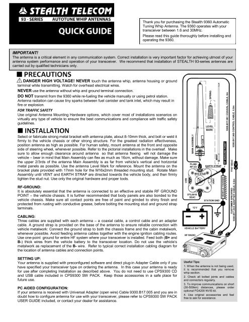
Thank you for purchasing the Stealth 9360 Automatic<br />
Tuning Whip Antenna. The 9360 operates with your<br />
transceiver between 1.6 and 30MHz.<br />
Please read this guide thoroughly before installing and<br />
operating the 9360.<br />
<strong>IMPORTANT</strong>!<br />
The antenna is a critical element in any communication system. Correct installation is very important factor for achieving utmost of your<br />
antenna system performance and operation of your transceiver. We recommend that installation of STEALTH 93-series antennas are<br />
carried out by qualified technicians only.<br />
DANGER HIGH VOLTAGE! NEVER touch the antenna whip, antenna housing or ground<br />
terminal while transmitting. Watch for overhead electrical wires.<br />
NEVER use the antenna without whip and ground terminal connection.<br />
DO NOT transmit from the 9360 while re-fueling the vehicle manually or using petrol station.<br />
Antenna radiation can cause tiny sparks between fuel canister and tank inlet, which may result in<br />
fire or explosion.<br />
<strong>FOR</strong> <strong>TRAFFIC</strong> <strong>SAFETY</strong><br />
Use original Antenna Mounting Hardware options, which cover most of installations scenarios on<br />
virtually any type of vehicle to ensure the best communications and compliance with traffic safety<br />
guidelines.<br />
Select or fabricate strong metal bracket with antenna plate, about 8-10mm thick, and bolt or weld it<br />
firmly to the vehicle chassis or other strong structure. For the greatest radiation effectiveness,<br />
position antenna as high as possible. For human safety, mount antenna at the front and opposite<br />
side of steering wheel, whenever possible. Refer to the pictorial installations in the overleaf. Make<br />
sure to allow enough clearance around antenna so that antenna flexing will not damage the<br />
vehicle – bear in mind that Main Assembly can flex as much as 16cm, without damage. Make sure<br />
the upper 2/3rds of the antenna Main Assembly is as far from vehicle’s vertical and horizontal<br />
metal panels as possible. Use the antenna Level Mark for reference. Mount the antenna on the<br />
bracket plate provided with 17mm hole for the M16x2mm threaded mounting stud. Rotate Main<br />
Assembly until VENT and EARTH STRAP are directed towards the vehicle body, and then firmly<br />
tighten the stud nut. Use only the original hardware and proper tools.<br />
RF-GROUND:<br />
It is absolutely essential that the antenna is connected to an effective and stabile RF GROUND<br />
POINT – the vehicle chassis. It is further recommended that body panels are also bonded to the<br />
vehicle chassis. Make sure all contact points are free of paint and grinded to shiny finish and<br />
protected from rusting with conductive grease, before bolting the mounting stud and ground strap<br />
terminals.<br />
CABLING:<br />
Three cables are supplied with each antenna – a coaxial cable, a control cable and an adapter<br />
cable. A ground strap is provided on the base of the antenna to ensure reliable connection with<br />
vehicle metalwork: Connect the ground strap to both the chassis frame and the cabin metalwork,<br />
whenever possible. Avoid feeding antenna cables together with the engine ignition cabling routes.<br />
Use one-point ground for entire HF system where your transceiver is installed. Feed both (B+ and<br />
B-) thick wires from the vehicle battery to the transceiver location. Do not use the vehicle’s<br />
metalwork as replacement of the B- wire. Refer to typical correct installation cabling diagram for<br />
the location of antenna cables and connection points.<br />
SETTING UP:<br />
Your antenna is supplied with preconfigured software and direct plug-in Adapter Cable only if you<br />
have specified your transceiver type on ordering the antenna. In this case your antenna is ready<br />
for use after completing Installation as described above. You do not need to use CPS9300 CD<br />
and USB cable included in CPS9300 SW PACK. Keep those accessories in a safe place for<br />
future use.<br />
PC AIDED CONFIGURATION:<br />
If your antenna is received with Universal Adapter (open wire) Cable 9300.B17.005 and you are in<br />
doubt how to configure antenna for use with your transceiver, please refer to CPS9300 SW PACK<br />
USER GUIDE included, or contact your dealer for assistance.<br />
Useful Tips:<br />
1. When the antenna is not being used,<br />
it is recommended that you remove<br />
whip section.<br />
2. Check all bolted joints and cables<br />
and connectors regularly.<br />
3. To improve communications on short<br />
(30-500km) distances, please order<br />
optional FG4200 NVIS kit.<br />
4. Use original accessories and feel<br />
free to ask for assistance.
◙ TYPICAL INSTALLATION SCENARIOS <strong>FOR</strong> STEALTH 93XX HF AUTOMATIC TUNING WHIP ANTENNAS<br />
For best communications, position the<br />
antenna as high as possible. Please use a<br />
Level Mark triangle as a reference when<br />
selecting an Universal Gibbet Raiser<br />
option. The picture to the left indicates<br />
preferred option selection considerations.<br />
The picture to the right indicates an<br />
antenna installation that uses optional<br />
FG4200 NVIS kit, for best communications<br />
on 30-500km short ranges.<br />
Most recommended SUV installation<br />
scenarios use Universal Gibbet Mount<br />
(front) or the customer provided Antenna<br />
Bracket (rear). Note the upper 2/3rd of the<br />
Antenna Main Assembly is kept clear of<br />
vehicle’s hood and other metal panels.<br />
Best communications in all directions is<br />
ensured.<br />
Recommended installation options on a<br />
typical sedan vehicle use Universal Gibbet<br />
Mount for both front and rear antenna<br />
locations. Note the upper 2/3 rd of Antenna<br />
Main Assembly is optimally raised above<br />
the trunk and hood of the vehicle.<br />
Recommended installation options on<br />
typical pick-up vehicle using an Universal<br />
Gibbet Mount (front) and an Universal<br />
Gibbet Raiser or a customer provided<br />
bracket (middle). Both methods provide<br />
effective communications in all directions.<br />
NON-RECOMMENDED methods of an<br />
antenna installation using a Universal<br />
Gibbet Mount (both at the rear) shown on<br />
typical minivan or 4WD vehicles. Note the<br />
entire Antenna Main Assembly and<br />
partially Whip Section are OBSTRUCTED<br />
by vehicle metal panels. Excessive RF<br />
losses in the vehicle metal and poor<br />
communications towards vehicle front side<br />
shall be expected.<br />
STEALTH TELECOM FZC<br />
93-SERIES ADVANCED ANTENNA SYSTEMS<br />
P.O. Box 7755, Sharjah, UAE 9300.D53.111 Issue 2 Printed in UAE<br />
www.stealth-tele.com<br />
© 2013 Stealth Telecom