Figure 2. Equivalent circuit of figure 1 if RE= R1+R2+R3 ... - Krypton
Figure 2. Equivalent circuit of figure 1 if RE= R1+R2+R3 ... - Krypton
Figure 2. Equivalent circuit of figure 1 if RE= R1+R2+R3 ... - Krypton

Create successful ePaper yourself
Turn your PDF publications into a flip-book with our unique Google optimized e-Paper software.
Supplementary Notes for Unit 2 - Part A<br />
(Unit 3 and 4 exams also includes the topics detailed in this note)<br />
EET-112: Elementary Electronics<br />
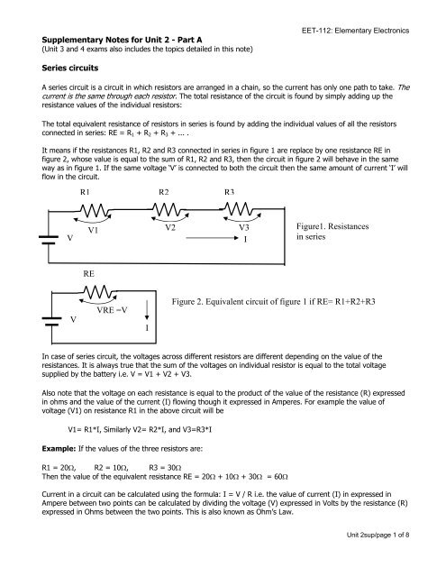
Series <strong>circuit</strong>s<br />
A series <strong>circuit</strong> is a <strong>circuit</strong> in which resistors are arranged in a chain, so the current has only one path to take. The<br />
current is the same through each resistor. The total resistance <strong>of</strong> the <strong>circuit</strong> is found by simply adding up the<br />
resistance values <strong>of</strong> the individual resistors:<br />
The total equivalent resistance <strong>of</strong> resistors in series is found by adding the individual values <strong>of</strong> all the resistors<br />
connected in series: RE = R 1 + R 2 + R 3 + ... .<br />
It means <strong>if</strong> the resistances R1, R2 and R3 connected in series in <strong>figure</strong> 1 are replace by one resistance RE in<br />
<strong>figure</strong> 2, whose value is equal to the sum <strong>of</strong> R1, R2 and R3, then the <strong>circuit</strong> in <strong>figure</strong> 2 will behave in the same<br />
way as in <strong>figure</strong> 1. If the same voltage ‘V’ is connected to both the <strong>circuit</strong> then the same amount <strong>of</strong> current ‘I’ will<br />
flow in the <strong>circuit</strong>.<br />
R1 R2 R3<br />
V<br />
V1<br />
V2<br />
V3<br />
I<br />
<strong>Figure</strong>1. Resistances<br />
in series<br />
RE<br />
V<br />
VRE =V<br />
I<br />
<strong>Figure</strong> <strong>2.</strong> <strong>Equivalent</strong> <strong>circuit</strong> <strong>of</strong> <strong>figure</strong> 1 <strong>if</strong> <strong>RE=</strong> <strong>R1+R2+R3</strong><br />
In case <strong>of</strong> series <strong>circuit</strong>, the voltages across d<strong>if</strong>ferent resistors are d<strong>if</strong>ferent depending on the value <strong>of</strong> the<br />
resistances. It is always true that the sum <strong>of</strong> the voltages on individual resistor is equal to the total voltage<br />
supplied by the battery i.e. V = V1 + V2 + V3.<br />
Also note that the voltage on each resistance is equal to the product <strong>of</strong> the value <strong>of</strong> the resistance (R) expressed<br />
in ohms and the value <strong>of</strong> the current (I) flowing though it expressed in Amperes. For example the value <strong>of</strong><br />
voltage (V1) on resistance R1 in the above <strong>circuit</strong> will be<br />
V1= R1*I, Similarly V2= R2*I, and V3=R3*I<br />
Example: If the values <strong>of</strong> the three resistors are:<br />
R1 = 20Ω, R2 = 10Ω, R3 = 30Ω<br />
Then the value <strong>of</strong> the equivalent resistance RE = 20Ω + 10Ω + 30Ω = 60Ω<br />
Current in a <strong>circuit</strong> can be calculated using the formula: I = V / R i.e. the value <strong>of</strong> current (I) in expressed in<br />
Ampere between two points can be calculated by dividing the voltage (V) expressed in Volts by the resistance (R)<br />
expressed in Ohms between the two points. This is also known as Ohm’s Law.<br />
Unit 2sup/page 1 <strong>of</strong> 8
EET-112: Elementary Electronics<br />
In the above example, <strong>if</strong> the battery has a voltage value <strong>of</strong> 10 V, then the total current in the <strong>circuit</strong> is: I = V/R<br />
= 10/60 = 1/6 Ampere = 0.166 A. The current through each resistor would be 0.166 A.<br />
Parallel <strong>circuit</strong>s<br />
A parallel <strong>circuit</strong> is a <strong>circuit</strong> in which the resistors are arranged with their heads connected together, and their<br />
tails connected together, as shown in <strong>figure</strong> 3a and is same in <strong>figure</strong> 3b shown in slightly d<strong>if</strong>ferent arrangements.<br />
The current in a parallel <strong>circuit</strong> breaks up, with some flowing along each parallel branch and re-combining when<br />
the branches meet again. The voltage across each resistor in parallel is the same, because all have the same<br />
common points.<br />
The total equivalent resistance <strong>of</strong> a set <strong>of</strong> resistors in parallel is found by adding up the reciprocals <strong>of</strong> the<br />
resistance values, and then taking the reciprocal <strong>of</strong> the total as shown below:<br />
1/RE = 1/R 1 + 1/R 2 + 1/R 3 +...<br />
It means <strong>if</strong> the resistances R1, R2 and R3 connected in parallel in <strong>figure</strong> 3a or 3b are replace by one resistance<br />
RE in <strong>figure</strong> 4, whose value is taken such that 1/RE = 1/R 1 + 1/R 2 + 1/R 3 , then the <strong>circuit</strong> in <strong>figure</strong> 3a or 3b will<br />
behave in the same way as in <strong>figure</strong> 4. If the same voltage ‘V’ is connected to both the <strong>circuit</strong> then the same<br />
amount <strong>of</strong> current ‘I’ will be generated in the <strong>circuit</strong>. However, in parallel <strong>circuit</strong>s the current supplied by the<br />
battery splits up in d<strong>if</strong>ferent values, and the amount going through each resistor depends on the resistance.<br />
I<br />
I1 I2 I3<br />
<strong>Figure</strong>3a. Resistances in parallel<br />
V<br />
R1 R2 R3<br />
V<br />
I<br />
I<br />
I1 I2 I3<br />
<strong>Figure</strong>3b. Resistances in parallel<br />
same as in 3a<br />
V<br />
R1 R2 R3<br />
I<br />
V<br />
I<br />
V<br />
I<br />
RE<br />
<strong>Figure</strong> 4. Resistances in parallel same<br />
as in 3a<br />
I<br />
Unit 2sup/page 2 <strong>of</strong> 8
EET-112: Elementary Electronics<br />
The values <strong>of</strong> I1, I2 and I3 will be depend on the values <strong>of</strong> R1, R2 and R3 respectively and will be discussed in<br />
the subsequent units. If R1=R2=R3, then the following relationship will be true: I1=I2=I3.<br />
The following relationship will always also be true. It means that the current flowing into a node will be equal to<br />
the sum <strong>of</strong> the current flowing out <strong>of</strong> the node.<br />
I = I1 + I2 + I3<br />
Example: If the values <strong>of</strong> the three resistors are:<br />
R1= 10Ω, R2=10Ω, and R3=20Ω Then the equivalent RE resistance can be calculated as<br />
1/RE = 1/10 + 1/10 + 1/20 = .1 + .1 + .05 = .25<br />
So, 1/RE = .25 i.e RE = 1/.25 = 4Ω<br />
Using the formula <strong>of</strong> Ohm’s Law, as used in series <strong>circuit</strong>, V=I/R we can calculate the current.<br />
In the above example, <strong>if</strong> the battery has a voltage value <strong>of</strong> 10 V, then the total current in the <strong>circuit</strong> is: I = V/R<br />
= 10/4 = <strong>2.</strong>5 A.<br />
As we discussed that for parallel <strong>circuit</strong> the voltage across each resistor is same i.e. 10 V, so:<br />
I 1 = V/R1 = 10/10 = 1 A<br />
I 2 = V/R2 = 10/10 = 1 A<br />
I 3 = V/R3 = 10/20 = 0.5 A<br />
Note that I1+I2+I3 = 1 + 1 + .5 = <strong>2.</strong>5 equals to the total current I=<strong>2.</strong>5A.<br />
Important points to Remember on Series and parallel Circuits:<br />
For Serial Circuits:<br />
- Series <strong>circuit</strong>s have only one path, so the amount <strong>of</strong> flow <strong>of</strong> current is same through all resistors. If any<br />
part <strong>of</strong> the series <strong>circuit</strong> is broken no current will flow through the <strong>circuit</strong>.<br />
- The amount <strong>of</strong> current in <strong>circuit</strong> is: I=V/RE. (V in volts, RE in Ohms and I in amperes)<br />
- Voltage on each resistor will be d<strong>if</strong>ferent depending on the value <strong>of</strong> the resistor.<br />
V1=IR1, V2=IR2, V3=IR3<br />
- The sum <strong>of</strong> the voltage on individual resistor is equal to the output voltage <strong>of</strong> the source.<br />
V = V1+ V2+ V3<br />
- The equivalent resistor in series can be calculated with the formulae: RE = <strong>R1+R2+R3</strong><br />
For Parallel Circuits:<br />
- Voltage is the same for along parallel paths, but current splits to d<strong>if</strong>ferent branches.<br />
- Parallel <strong>circuit</strong>s have two or more paths for flow <strong>of</strong> current. Amount <strong>of</strong> current through a path depends on<br />
the value <strong>of</strong> the resistors. Formulas; I1 = V/R1, I2 = V/R2 and I3 = V/R3<br />
- The sum <strong>of</strong> the current through individual path is equal to the total current that flows from the source.<br />
I = I1+ I2 + I3<br />
- The equivalent resistor in parallel can be calculated with the formulae: 1/<strong>RE=</strong>1/R1+1/R2+1/R3<br />
- If one <strong>of</strong> the parallel path is broken, current will continue to flow through the remaining path.<br />
- If one <strong>of</strong> the parallel path is short <strong>circuit</strong>ed (i.e. connected with a wire meaning resistance =0) then all<br />
current will flow through the short <strong>circuit</strong> and RE will become zero ohm.<br />
Visit the URL: ‘http://home.att.net/~basicelectronics/parallel.htm’ for more explanation with <strong>figure</strong>s and in an<br />
easy to understand approach.<br />
Also visit: http://www.antonine-education.co.uk/Physics_AS/Module_3/Topic_3/topic_3__series_and_parallel_cir.htm<br />
Circuits with combination <strong>of</strong> series and parallel components<br />
Many <strong>circuit</strong>s have a combination <strong>of</strong> series and parallel resistors. Generally, the total resistance in such a <strong>circuit</strong> is<br />
found by reducing the d<strong>if</strong>ferent series and parallel combinations step-by-step to end up with a single equivalent<br />
Unit 2sup/page 3 <strong>of</strong> 8
EET-112: Elementary Electronics<br />
resistance for the <strong>circuit</strong>. This allows the current from the source to be determined easily. The current flowing<br />
through each resistor can then be found by undoing the reduction process.<br />
General rules for doing the reduction process may be completed in the following steps:<br />
1. First, each <strong>of</strong> the parallel connections can be reduced to one resistor using the equivalent resistance<br />
equation for resistors in parallel. Note that two (or more) resistors with their heads directly connected<br />
together and their tails directly connected together are in parallel.<br />
<strong>2.</strong> In the next step the resistors (including the equivalent resistors calculate from the parallel connections) in<br />
series can be reduced to one equivalent resistor using the equation for resistors in series. Note that two<br />
resistors connected together so that the tail <strong>of</strong> one is connected to the head <strong>of</strong> the next, with no other<br />
path for the current to take along the line connecting them, are in series.<br />
A parallel resistor short-cut<br />
If the resistors in parallel are identical, it can be very easy to work out the equivalent resistance. In this case the<br />
equivalent resistance <strong>of</strong> N identical resistors is the resistance <strong>of</strong> one resistor divided by N, the number <strong>of</strong><br />
resistors. So, two 40-ohm resistors in parallel are equivalent to one 20-ohm resistor (40/2 ohm); five 40-ohm<br />
resistors in parallel are equivalent to one 8-ohm resistor, (40/8) etc.<br />
When calculating the equivalent resistance <strong>of</strong> a set <strong>of</strong> parallel resistors, do not forget to flip the 1/RE upside<br />
down, putting 1/5 <strong>of</strong> an ohm instead <strong>of</strong> 5 ohms, for instance.<br />
Alternating Current - Periodic Signal<br />
Direct current (DC) from a battery moves in one direction only, from positive to negative. In alternating<br />
current (AC) the direction is changing all the time. Power supplies in our homes are AC supply and are periodic<br />
in nature.<br />
http://www.kpsec.freeuk.com/acdc.htm<br />
• The signal in the graph is called a sinusoidal waveform or a sine wave.<br />
• Amplitude is the maximum voltage reached by the signal. It is measured in volts, V. Amplitude is also<br />
known as Peak Voltage.<br />
• Peak-to-peak voltage is twice the peak voltage (amplitude).<br />
• One complete alternation that is repeated over time is called a cycle. The Time Period is the time taken<br />
for one cycle. It is measured in seconds (s). Normally time period tends to be very small. So it is <strong>of</strong>ten<br />
expressed in milliseconds (ms, one thousandth part <strong>of</strong> a second: 10 -3 seconds or 0.001s), microseconds<br />
(µs, one millionth <strong>of</strong> a second: 10 -6 seconds or 0.0000001s), nanoseconds (10 -9 seconds) etc.<br />
• The frequency is the number <strong>of</strong> cycles in one second. Units are hertz (Hz). 1 Hz means that the signal<br />
has 1 cycle in 1 second. Frequencies tend to be very high. So, it is <strong>of</strong>ten expressed in kilohertz (KHz;<br />
1000 Hz or 10 3 Hz), Megahertz (MHz; 1,000,000 Hz or 10 6 Hz) etc. 1 KHz means that the signal has<br />
1000 cycles in 1 second i.e. the period will be 1/1000 second or 1 millisecond. Similarly, a signal with<br />
frequency <strong>of</strong> 1 MHz will have a period <strong>of</strong> 1 microseconds).<br />
Unit 2sup/page 4 <strong>of</strong> 8
EET-112: Elementary Electronics<br />
• If frequency is denoted by f and period by T, then the formula is f = 1/T.<br />
• The current follows exactly the same wave form as voltage.<br />
• The terminologies frequency, period, cycles etc. are applicable to all signals that are periodic in nature<br />
e.g. triangular, square wave etc.<br />
The frequency <strong>of</strong> AC supply is 50 Hz (cycles per second) in UK; 60 Hz in USA. A frequency <strong>of</strong> 50 Hz means a<br />
period <strong>of</strong> 1/50 = .02s = 20ms.<br />
Root Mean Square (RMS) Values<br />
The value <strong>of</strong> an AC voltage is continually changing. We use the root<br />
mean square voltage (V RMS ) to express AC signals. RMS is expressed<br />
in terms <strong>of</strong> peak voltage (V peak ) given by the following formula:<br />
V RMS = 0.7 × V peak OR V peak = 1.4 × V RMS<br />
These equations also apply to current. These equations apply only for<br />
sine waves, which is the most common type <strong>of</strong> AC. The values 0.7 and<br />
1.4 are d<strong>if</strong>ferent other shapes.<br />
The RMS value is the effective value <strong>of</strong> a varying voltage or current. It is the equivalent steady DC (constant)<br />
value which gives the same effect.<br />
For example, a lamp connected to a 6V RMS AC supply will light with the same brightness when connected to a<br />
steady 6V DC supply. However, the lamp will be dimmer <strong>if</strong> connected to a 6V peak AC supply because the RMS<br />
value <strong>of</strong> this is only 4.2V (it is equivalent to a steady 4.2V DC). In everyday use AC voltages (and currents) are<br />
always given as RMS values. It should be clearly stated <strong>if</strong> peak value is indicated.<br />
Note that RMS value is NOT average value <strong>of</strong> the signal. In fact the average voltage (or current) <strong>of</strong> an AC sine<br />
wave signal is zero because the positive and negative parts exactly cancel out.<br />
Visit URL http://www.kpsec.freeuk.com/acdc.htm for more details.<br />
Measuring Instruments and Power Sources:<br />
Measuring Instruments: Voltmeter, Ammeter, Multimeter, Oscilloscope<br />
Power Sources: DC power supply and Function Generator<br />
Read from the lab manual.<br />
See the ‘supplementary material for unit 2 - Part B’, posted on this subject’s web page, that includes<br />
picture <strong>of</strong> equipments with explanations that are used for unit 2 and subsequent experiments.<br />
Important points to Remember on Measuring Instruments:<br />
- For measurement <strong>of</strong> current the instrument must be connected in series to the measuring path, as shown<br />
in the <strong>figure</strong>. For example, for measuring current in each <strong>of</strong> the parallel path <strong>of</strong> resistances R1, R2 and<br />
R3 the ammeters (A1, A2, and A3) must be in series with each <strong>of</strong> the resistors R1, R2 and R3. If you<br />
have only one measuring instrument you can measure one after the other.<br />
Unit 2sup/page 5 <strong>of</strong> 8
EET-112: Elementary Electronics<br />
- The resistance <strong>of</strong> current measuring instrument is low.<br />
- For measurement <strong>of</strong> voltage the measuring instrument must be connected in parallel between the two<br />
points for which the voltage is to be measured, as shown in the following <strong>figure</strong>. For example, for<br />
measuring voltage across resistance R1 it should be placed in parallel to R1 and so on.<br />
- The resistance <strong>of</strong> voltage measuring instrument is very high.<br />
- For measurement <strong>of</strong> resistance the power supply must be disconnected from the <strong>circuit</strong>. The instrument<br />
applies a known voltage across the resistor and measures the current to determine the value <strong>of</strong> the<br />
resistance.<br />
- You must set the appropriate range before start <strong>of</strong> measurement. The range must be a set to a higher<br />
value than the expected measured value.<br />
- You must make sure that the connections made are appropriate to the quantity you want to measure. For<br />
example, to measure resistance with a multimeter the jacks must be connected to COM and Ω inputs <strong>of</strong><br />
the multimeter. The measurement select switch must be in the ohm (Ω) measuring position and proper<br />
range selected.<br />
- Oscilloscope measures only voltage and have high input resistance. Read the manual for selection <strong>of</strong> the<br />
volts/div and Time/div switches.<br />
- AC voltmeters and ammeters show the RMS value <strong>of</strong> the voltage or current. DC meters also show the<br />
RMS value when connected to varying DC providing the DC is varying quickly, <strong>if</strong> the frequency is less<br />
than about 10Hz you will see the meter reading fluctuating instead.<br />
Fig. Source - http://www.antonine-education.co.uk/Physics_AS/Module_3/Topic_3/topic_3__series_and_parallel_cir.htm<br />
Unit 2sup/page 6 <strong>of</strong> 8
EET-112: Elementary Electronics<br />
Some Equipments Used in Unit2 and subsequent experiments<br />
Dual Power Supply<br />
Knob for setting the<br />
output voltage value<br />
<strong>of</strong> the second power<br />
supply<br />
Knob for setting<br />
the output voltage<br />
value <strong>of</strong> the first<br />
power supply<br />
Power Switch<br />
Setting the<br />
range <strong>of</strong> the<br />
value <strong>of</strong> output<br />
voltage<br />
Two (’+’ for positive<br />
voltage, and ‘-‘ for<br />
negative voltage)<br />
Outputs <strong>of</strong> the first<br />
<strong>of</strong> the two Power<br />
Supply<br />
Ground:<br />
Power supply<br />
output is taken<br />
from ground<br />
and one output<br />
(‘ ’ ‘ ‘)<br />
Two (’+’ for positive<br />
voltage, and ‘-‘ for<br />
negative voltage)<br />
Outputs <strong>of</strong> the<br />
second <strong>of</strong> the two<br />
Power Supply<br />
Digital Multimeter<br />
Range<br />
V-Ω Jack<br />
for voltage<br />
Power<br />
Switch<br />
COM Jack<br />
A Jack for<br />
current<br />
Unit 2sup/page 7 <strong>of</strong> 8
EET-112: Elementary Electronics<br />
Dual Power Supplies<br />
Function Generator<br />
Power<br />
Switch<br />
Function Generator<br />
Multimeter<br />
Dual Power Supplies<br />
An Integrated Unit containing Dual Power<br />
Supply, Digital Multimeter, Function Generator<br />
Analog Multimeter<br />
Output reading scales. The<br />
reading scale corresponds to<br />
the range selected below<br />
Range Selector. Note<br />
separate range for Ohms,<br />
voltage and current<br />
Unit 2sup/page 8 <strong>of</strong> 8