Automation platform Modicon Premium - Schneider Electric
Automation platform Modicon Premium - Schneider Electric
Automation platform Modicon Premium - Schneider Electric

Create successful ePaper yourself
Turn your PDF publications into a flip-book with our unique Google optimized e-Paper software.
<strong>Automation</strong> <strong>platform</strong><br />
<strong>Modicon</strong> <strong>Premium</strong><br />
Catalogue<br />
2008
�<br />
Global Detection<br />
Electronic and<br />
electromechanical sensors<br />
n° 960262<br />
MKTED208052EN<br />
Photo-electric sensors<br />
Proximity sensors<br />
Capacitive proximity sensors<br />
Ultrasonic sensors<br />
Limit switches<br />
Pressure switches<br />
Rotary encoders<br />
Radio frequency identifi cation<br />
Machine cabling accessories<br />
�<br />
<strong>Modicon</strong> Momentum<br />
distributed I/O and control<br />
n° 807861<br />
MKTED205061EN<br />
�<br />
<strong>Modicon</strong> Quantum<br />
automation <strong>platform</strong>, Unity,<br />
Concept & ProWORX 32<br />
n° 960237<br />
MKTED208011EN<br />
�<br />
<strong>Modicon</strong> <strong>Premium</strong> and<br />
Unity - PL7 software<br />
n° 960268<br />
MKTED208054EN<br />
�<br />
<strong>Modicon</strong> M340 and<br />
Unity software<br />
n° 960128<br />
DIAED2061001EN<br />
PLCs<br />
Discrete, analogue I/O and<br />
application-specifi c solutions<br />
Communication<br />
A full range of catalogues for . . . . .<br />
Safety Functions<br />
and Solutions<br />
using Preventa<br />
Catalogue<br />
2008/2009<br />
Detection <strong>Automation</strong> <strong>Automation</strong> Operator dialog Motion and Drives<br />
�<br />
Twido programmable<br />
controller and TwidoSuite<br />
software<br />
n° 960211<br />
DIA3ED2070902EN<br />
Controller base<br />
Discrete, analogue I/O<br />
Communication<br />
�<br />
<strong>Automation</strong> functions,<br />
relays, interfaces and<br />
power supplies<br />
n° 960162<br />
MKTED207031EN<br />
Smart relays<br />
Timing relays<br />
Measurement & control relays<br />
Analogue interfaces<br />
Counters<br />
Plug-in relays<br />
Interfaces for discrete signals<br />
Power supplies & transformers<br />
Software<br />
PLCs and safety controllers<br />
programming software<br />
�<br />
Control and signalling<br />
components<br />
n° 960239<br />
MKTED208031EN<br />
Control and signalling units<br />
Control stations & enclosures<br />
Cam switches<br />
Beacons and indicator banks<br />
Pendant control stations<br />
Controllers<br />
Emergency stops<br />
Foot switches<br />
�<br />
Human-Machine interfaces<br />
n° 821230<br />
MKTED206071EN<br />
Operator interface terminals<br />
Industrial PCs<br />
HMI and SCADA PC-based<br />
software<br />
Software<br />
Vijeo Designer<br />
Operator terminal software<br />
Not all products shown in this catalogue are available in every country. Check individual country’s web site or Sales Offi ce for product availability.<br />
See on: www.schneider-electric.com<br />
�<br />
Motion control Lexium 05<br />
n° 808610<br />
DIA7ED2050910EN<br />
�<br />
Motion control Lexium 15<br />
n° 816811<br />
DIA2ED2060506EN<br />
�<br />
Lexium Controller motion<br />
controllers<br />
n° 960165<br />
DIA7ED2070410EN<br />
Servo drives and Servo motors<br />
Motion controllers<br />
Motion control modules<br />
<strong>Modicon</strong> <strong>Premium</strong> and <strong>Modicon</strong><br />
Quantum<br />
�<br />
Soft starters and variable<br />
speed drives<br />
n° 960142<br />
MKTED206111EN<br />
Soft starters and variable speed<br />
drives<br />
Software<br />
Software for drives and motors<br />
Motor control programming<br />
software
. . . . all <strong>Automation</strong> & Control functions<br />
Motor control Machine safety Interfaces and I/O Power supplies Systems & architectures<br />
&<br />
Motor starter solutions<br />
Control and protection<br />
components<br />
n° 814711<br />
MKTED205103EN<br />
Contactors<br />
Circuit-breakers, fuse carriers<br />
Thermal relays<br />
Combinations, motor controllers<br />
Mounting solutions<br />
Motor starter mounting kits<br />
This catalogue contains<br />
<strong>Automation</strong> and Control function<br />
products relating to machines<br />
Safety<br />
&<br />
Safety functions and<br />
solutions using Preventa<br />
n° 960260<br />
MKTED208051EN<br />
Safety PLCs<br />
Safety controllers<br />
Safety monitors<br />
Safety solutions on AS-Interface<br />
cabling system<br />
Safety switches<br />
Safety light curtains<br />
Safety mats<br />
Emergency stops<br />
Control stations<br />
Enabling switches<br />
Foot switches<br />
Beacons & indicator banks<br />
Switch disconnectors<br />
Thermal-magnetic motor circuit<br />
breakers<br />
Enclosed D.O.L. starters<br />
Software<br />
XPSMFWIN configuration<br />
software<br />
XPSMCWIN configuration<br />
software<br />
&<br />
Interfaces, I/O splitter boxes<br />
and power supplies<br />
n° 70263<br />
MKTED203113EN<br />
Discrete interfaces<br />
Pre-wired interfaces<br />
IP 67 Splitter boxes<br />
&<br />
Terminal blocks<br />
n° 960151<br />
MKTED207011EN<br />
Terminal blocks<br />
Cable ends<br />
&<br />
IP 20 distributed<br />
inputs/outputs Advantys STB<br />
n° 960266<br />
MKTED208053EN<br />
Modules for automation island<br />
Network interfaces<br />
Power distribution<br />
Digital I/O, analogs and<br />
application-specific<br />
Software<br />
STB configuration software<br />
&<br />
Power supplies and<br />
transformers Phaseo<br />
n° 822591<br />
DIA3ED2061209EN<br />
Switch mode power supplies<br />
Filtered rectified power supplies<br />
Transformers<br />
This catalogue contains<br />
<strong>Automation</strong> and Control function<br />
products relating to<br />
Communication<br />
&<br />
Machine & Installations with<br />
industrial communication<br />
n° 960153<br />
MKTED207012EN<br />
Preferred implementations<br />
Ethernet TCP/IP, the universal<br />
communication standard<br />
CANopen for machines and<br />
installations<br />
AS-interface, simple and safe<br />
Products<br />
Human-Machine interface<br />
Controllers and PLCs<br />
Field devices<br />
Infrastructure and wiring<br />
Gateways<br />
Software and tools<br />
Collaborative <strong>Automation</strong><br />
Partner Program & Partners
1<br />
2<br />
3<br />
4<br />
5<br />
6<br />
7<br />
8<br />
9<br />
10<br />
General Contents<br />
2<br />
<strong>Modicon</strong> <strong>Premium</strong><br />
automation <strong>platform</strong><br />
1 – <strong>Premium</strong> processors<br />
Unity selection guide ........................................ page 1/2<br />
Unity processors ........................................... page 1/4<br />
Unity slot-PLCs ........................................... page 1/14<br />
PL7 selection guide ........................................ page 1/24<br />
PL7 processors ........................................... page 1/26<br />
2 – Racks, I/O architectures and power supplies<br />
Power supply and fan modules ................................ page 2/2<br />
Single rack configuration . . . . . . . . . . . . . . . . . . . . . . . . . . . . . . . . . . . . page 2/6<br />
Multi-racks configuration without remote module . . . . . . . . . . . . . . . . page 2/8<br />
Multi-racks configuration with remote module . . . . . . . . . . . . . . . . . . page 2/12<br />
3 – Discrete and analog I/O<br />
Discrete I/O modules ........................................ p age 3/2<br />
Analog I/O modules ........................................ page 3/20<br />
Distributed I/O modules ..................................... page 3/28<br />
TeSys Quickfit for motor starter components ................... page 3/42<br />
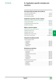
4 – Application-specific modules and solutions<br />
Preventa safety modules ..................................... page 4/2<br />
Counter and electronic cam modules .......................... page 4/18<br />
Motion control modules ..................................... page 4/32<br />
MFB, Motion Function Blocks . . . . . . . . . . . . . . . . . . . . . . . . . . . . . .see page 9/20<br />
Integrated weighing system ................................. page 4/56<br />
Hot Standby redundancy (Unity) . . . . . . . . . . . . . . . . . . . . . . . . . . . . . . page 4/62<br />
Warm Standby redundancy (PL7) ............................. page 4/72<br />
5 – Communication<br />
Selection guides ............................................ page 5/2<br />
Ethernet network - Transparent Ready ......................... page 5/12<br />
CANopen machine bus ..................................... page 5/62<br />
AS-Interface sensor/actuators bus ............................ page 5/68<br />
X-Way bus and network ..................................... page 5/74<br />
Modbus Plus network and Profibus DP/InterBus buses . . . . . . . . . . . . page 5/90<br />
Modbus, Uni-Telway and asynchronous serial links ............. page 5/100
General Contents<br />
6 – Software<br />
Unity software ............................................. page 6/2<br />
PL7 software .............................................. page 6/60<br />
Vijeo Citect supervisory software . . . . . . . . . . . . . . . . . . . . . . . . . . . . . page 6/90<br />
OPC data server software . . . . . . . . . . . . . . . . . . . . . . . . . . . . . . . . . . page 6/100<br />
7 – Human/Machine Interfaces<br />
Magelis Small Panel units and terminals ........................ page 7/2<br />
Magelis Advanced Panel ..................................... page 7/4<br />
HMI software ............................................... page 7/6<br />
8 – Connection interfaces and power supplies<br />
Advantys Telefast ABE 7 pre-wired system ...................... page 8/2<br />
Phaseo Universal range power supplies ....................... page 8/20<br />
9 – Services<br />
Treatement for severe environments,<br />
Conformal Coating <strong>Premium</strong> modules ......................... page 9/2<br />
TSX PSY power supply module selection document . . . . . . . . . . . . . . page 9/6<br />
Technical information<br />
Standards, certifications and environment conditions ............. page 9/8<br />
Ethernet network, infrastructure . . . . . . . . . . . . . . . . . . . . . . . . . . . . . page 9/12<br />
<strong>Automation</strong> product certifications ............................ page 9/18<br />
Index<br />
Product reference index ....................................page 9/22<br />
3<br />
1<br />
2<br />
3<br />
4<br />
5<br />
6<br />
7<br />
8<br />
9<br />
10
1<br />
2<br />
3<br />
4<br />
5<br />
6<br />
7<br />
8<br />
9<br />
10<br />
1/0
Contents<br />
1 - <strong>Modicon</strong> <strong>Premium</strong> processors<br />
<strong>Premium</strong> processors - Unity<br />
Processors and slot-PLCsSelection guide �� ��������������������������������������������page 1/2<br />
b <strong>Premium</strong> processors<br />
v Presentation ............................................. page 1/4<br />
v Description .............................................. page 1/5<br />
v Memory structure ......................................... page 1/8<br />
v Characteristics .......................................... page 1/10<br />
v References ............................................ page 1/12<br />
b Atrium slot-PLCs<br />
v Presentation ............................................ page 1/14<br />
v Description ............................................. page 1/16<br />
v TCP/X-Way software gateway .............................. page 1/17<br />
v Memory structure ........................................ page 1/18<br />
v Characteristics .......................................... page 1/20<br />
v References ............................................ page 1/21<br />
b PCMCIA memory extension cards ............................. page 1/22<br />
<strong>Premium</strong> processors - PL7<br />
Processors Selection guide �� ������������������������������������������������������������������page 1/24<br />
b <strong>Premium</strong> processors<br />
v Presentation ............................................ page 1/26<br />
v Description ............................................. page 1/27<br />
v Characteristics .......................................... page 1/28<br />
v Memory structure ........................................ page 1/30<br />
v References ............................................ page 1/31<br />
b PCMCIA memory extension cards ............................. page 1/32<br />
1/1<br />
1<br />
2<br />
3<br />
4<br />
5<br />
6<br />
7<br />
8<br />
9<br />
10
1<br />
2<br />
3<br />
4<br />
5<br />
6<br />
7<br />
8<br />
9<br />
10<br />
Selection guide<br />
1/2<br />
<strong>Modicon</strong> <strong>Premium</strong> automation<br />
<strong>platform</strong><br />
<strong>Premium</strong> processors and Atrium slot PLCs<br />
Unity<br />
<strong>Premium</strong>/Atrium <strong>platform</strong>s for Unity Pro software offer TSX 57 0p processor TSX 57 1p processors<br />
Number of racks (according to rack type) 1 with 4, 6, 8 or 12 slots 4 with 4, 6, or 8 slots or 2 with 12 slots<br />
In-rack I/O (1) Discrete I/O 256 channels (8-, 16-, 32- or 64-channel<br />
module)<br />
In-rack applicationspecific<br />
channels<br />
Serial link<br />
connections<br />
512 channels (8-, 16-, 32- or 64-channel<br />
module)<br />
Analog I/O 12 channels (4-, 8- or 16-channel module) 24 channels (4-, 8- or 16-channel module)<br />
Max. no. of channels 4 8<br />
Integrated counter (max. 40 kHz) –<br />
Counter Modules with 2/4 counter channels 1 MHz max., single-channel electronic cam module<br />
Motion (2) Modules with 1/2 axes for stepper motors, 2/3/4 axes for analog control servo motors, 8/16 axes<br />
with SERCOS digital link<br />
Weighing Module for 8 load cells (2 application-specific channels)<br />
Serial links TSX SCY in-rack communication modules (1 application-specific channel)<br />
Modbus RS 232, RS 485 or current loop (3) (4) master/slave PCMCIA modules and RS 485 master/<br />
slave in-rack communication modules<br />
Uni-Telway 1 integrated RS 485 master/slave channel, RS 232, RS 485 or current loop (3) (4) master/slave<br />
PCMCIA modules and RS 485 master/slave in-rack communication modules<br />
Character mode 1 integrated RS 485 channel, RS 232, RS 485 or current loop PCMCIA modules (3) (4)<br />
and RS 485 in-rack communication modules<br />
Bus connections AS-Interface actuator/sensor<br />
bus master V2<br />
1 in-rack module 2 in-rack modules<br />
CANopen machine bus<br />
master V4.02<br />
1 integrated PCMCIA module 1 PCMCIA module (3)<br />
InterBus fieldbus master V2 (5) or<br />
Profibus DP fieldbus master V0<br />
Class 1 and 2 (5)<br />
–<br />
Network connections Max. no. of networks 1<br />
Integrated process<br />
control<br />
Ethernet Multiprotocol in-rack modules (Modbus /TCP, Uni-TE, Global Data, I/O Scanning, TCP Open),<br />
Web server, FactoryCast server or FactoryCast HMI server<br />
Fipway/Ethway/Modbus Plus<br />
modules<br />
Configurable loops –<br />
Programmable loops Process control EFB library<br />
Hot Standby availability –<br />
Fipway module (4), Ethway in-rack modules Modbus Plus (3), Fipway (3)(4) modules,<br />
Ethway in-rack modules<br />
Memory capacity Without PCMCIA extension 96 Kb program and data 96 Kb program and data<br />
With PCMCIA extension 128 Kb program<br />
96 Kb data<br />
224 Kb program<br />
96 Kb data<br />
Data storage 256 Kb (PCMCIA extension in upper slot (0) on processor)<br />
USB programming port –<br />
Power supply 100…240 V a, 24 c non-isolated and 24…48 V c isolated power supply. A power supply is<br />
required for each rack.<br />
<strong>Premium</strong> processor Standard TSX P57 104M<br />
Integrated Ethernet<br />
(9)<br />
TSX P57 1634 g<br />
Integrated CANopen TSX P57 0244M<br />
Integrated Fipio TSX P57 154M (11)<br />
Atrium slot PLC Standard<br />
Integrated Fipio<br />
Pages 1/12<br />
(1) The maximum values for the numbers of discrete and analog I/O are cumulative (with the exception of TSX H57 24M/44M Hot Standby processors) .<br />
(2) 1 axis = 1 application-specific channel, except for SERCOS modules where, depending on the configuration, the module = 2…32 channels.<br />
(3) Module to be inserted into the lower PCMCIA slot (no . 1) on a <strong>Premium</strong> processor or into the external PCMCIA slot (no . 1) on an Atrium slot PLC .<br />
(4) Module to be inserted into the TSX SCY 21 601 in-rack communication module slot .<br />
(5) The InterBus and Profibus DP limits are not cumulative.<br />
(11) The TSX P57 154M processor does not support the CANopen bus PCMCIA module .<br />
g
TSX 57 2p processors and slot PLCs<br />
1 with 6, 8 or 12<br />
slots<br />
512 channels (64channel<br />
modules)<br />
80 channels (16channel<br />
modules)<br />
TSX 57 3p processors and slot<br />
PLCs<br />
TSX 57 4p processors<br />
16 with 4, 6, or 8 slots or 8 with 12 slots 1 with 6, 8 or 12<br />
slots<br />
1024 channels (8-, 16-, 32- or 64-channel modules) 512 channels (64channel<br />
modules)<br />
80 channels (4-, 8- or<br />
16-channel modules)<br />
128 channels (4-, 8- or 16-channel<br />
modules)<br />
128 channels (16channel<br />
modules)<br />
18 24 32 18 64<br />
–<br />
– Modules with 2/4 counter channels, single-channel<br />
electronic cam<br />
– Modules with 1/2 axes for stepper motors, 2/3/4 axes for<br />
servo motors, 8/16 axes with SERCOS digital link<br />
TSX 57 5p<br />
processors<br />
16 with 4, 6, or 8 slots or 8 with 12 slots<br />
TSX 57 6p<br />
processors<br />
2048 channels (8-, 16-, 32- or 64-channel modules)<br />
256 channels (4-, 8- or<br />
16-channel modules)<br />
512 channels (4-, 8- or 16-channel<br />
modules)<br />
– Modules with 2/4 counter channels, single-channel electronic<br />
cam<br />
– Modules with 1/2 axes for stepper motors, 2/3/4 axes for<br />
servo motors, 8/16 axes with SERCOS digital link<br />
– Module for 8 load cells (2 application-specific channels) – Module for 8 load cells (2 application-specific channels)<br />
TSX SCY in-rack communication modules (1 application-specific channel)<br />
RS 232, RS 485 or current loop (3) (4) master/slave PCMCIA modules and RS 485 master/slave in-rack communication modules<br />
1 integrated RS 485 master/slave channel, RS 232, RS 485 or current loop (3) (4) master/slave PCMCIA modules and RS 485 master/slave in-rack<br />
communication modules<br />
1 integrated RS 485 channel, RS 232, RS 485 or current loop PCMCIA modules (3) (4) and RS 485 in-rack communication modules<br />
– 4 in-rack modules 8 in-rack modules – 8 in-rack modules<br />
– 1 PCMCIA module (3) – 1 PCMCIA module (3)<br />
– 1 in-rack module 3 in-rack modules – 4 in-rack modules 5 in-rack modules<br />
2 1 + for Atrium,<br />
1 software gateway<br />
3 3 + 1 software<br />
gateway<br />
Multiprotocol in-rack modules (Modbus/TCP, Uni-TE, Global Data, I/O Scanning (6), TCP Open), Web server, FactoryCast server or FactoryCast HMI server and<br />
via software gateway with Atrium slot PLCs<br />
– Modbus Plus (3), Fipway (3)(4) module,<br />
Ethway in-rack modules<br />
4<br />
– Modbus Plus (3), Fipway (3) (4) (7) module,<br />
Ethway in-rack modules<br />
10 channels with 3 loops max. 15 channels with 3 loops max. 20 channels with 3 loops max. 30 channels with 3 loops max.<br />
Process control EFB library<br />
Yes – Yes –<br />
160/192 Kb program and data (8) 192/208 Kb program and data (8) 440 Kb program and data 1 Mb program and 2 Mb program and<br />
data<br />
data<br />
768 Kb program<br />
1.75 Mb program<br />
2 Mb program<br />
7 Mb program 7 Mb program<br />
160/192 Kb data (8)<br />
192/208 Kb data (8)<br />
440 Kb data<br />
1 Mb data 2 Mb data<br />
8 Mb (PCMCIA extension in upper or lower slot (0 or 1) on processor)<br />
– 1<br />
100…240 V a, 24 V c non-isolated and 24…48 V c isolated power supply. A power supply is required for each rack.<br />
TSX H57 24M<br />
(10)<br />
n n n<br />
TSX P57 204M TSX P57 304M<br />
TSX P57 2634M TSX P57 3634M TSX H57 44M<br />
(10)<br />
TSX P57 4634M TSX P57 5634M TSX P57 6634M<br />
TSX P57 254M<br />
TSX PCI 57 204M<br />
TSX P57 354M TSX P57 454M TSX P57 554M<br />
4/69 1/12 1/12<br />
TSX PCI 57 354M<br />
1/21 1/13 4/69 1/13<br />
(6) TSX H57 24M/44M Hot Standby processors do not support the Ethernet I/O Scanning service.<br />
(7) TSX P57 4634M/5634M/6634M processors with integrated Ethernet port do not support the PCMCIA Fipway card.<br />
(8) The second value applies to TSX P57 254M/354M processors with integrated Fipio link and to the TSX H57 24M Hot Standby processor .<br />
(9) The integrated Ethernet port requires one of the available network connections.<br />
(10) The integrated Ethernet port is dedicated to Hot Standby communication (CPU Sync link between “Primary” and “Redundant” processors).<br />
n New feature<br />
1/3<br />
1<br />
2<br />
3<br />
4<br />
5<br />
6<br />
7<br />
8<br />
9<br />
10
1<br />
2<br />
3<br />
4<br />
5<br />
6<br />
7<br />
8<br />
9<br />
10<br />
Presentation<br />
Description:<br />
pages 1/5 …<br />
1/4<br />
Memory structure:<br />
pages 1/8…<br />
<strong>Modicon</strong> <strong>Premium</strong><br />
automation <strong>platform</strong><br />
Unity processors<br />
Presentation<br />
<strong>Modicon</strong> <strong>Premium</strong> TSX P57 pp4M, TSX P57 pp34M and TSX Hp4M automation<br />
<strong>platform</strong> processors manage the entire PLC station comprising:<br />
b Discrete I/O modules<br />
b Preventa safety modules<br />
b Analog I/O modules<br />
b Application-specific modules (counter, motion, weighing, communication)<br />
n The <strong>Premium</strong> processor offer has seen the addition of three new references:<br />
b TSX P57 6634M, high-end processor with 1 integrated Ethernet Modbus/TCP port<br />
and an internal 2 Mb RAM<br />
b TSX H57 24M/44M, which support the Hot Standby system (with "Primary" and<br />
"Secondary" PLCs), see pages 4/60 to 4/69<br />
The processors differ in terms of their memory capacities, processing speeds, the<br />
number of I/O and the number of communication ports.<br />
Depending on the model, they include:<br />
b 1 to 16 racks interconnected by means of Bus X (max. distance: 700 m)<br />
b 192 to 2040 discrete I/O<br />
b 12 to 512 analog I/O<br />
b 4 to 64 application-specific channels. Each application-specific module (counter<br />
motion control, communication or weighing) accounts for one or more applicationspecific<br />
channels.<br />
b 1 to 4 networks (Ethernet Modbus/TCP, Fipway, Modbus Plus, Ethway), 1 to 8<br />
AS-Interface buses<br />
b 0 or 1 Fipio bus, 0 or 1 CANopen or Modbus Plus bus and 0 to 5 InterBus or<br />
Profibus DP (1) fieldbuses<br />
b 0 to 30 process control channels, with each channel capable of supporting up to<br />
3 loops<br />
Depending on the model, <strong>Premium</strong> processors also feature:<br />
b A 10BASE-T/100BASE-TX Ethernet Modbus/TCP port (RJ45 connector)<br />
b A 1 Mbit/s Fipio bus link (bus manager)<br />
b Communication via 2 terminal ports (TER and AUX) using Uni-Telway or character<br />
mode protocol (typically a 19 or 115 Kbit/s programming terminal and an operator<br />
dialogue terminal)<br />
b A USB type TER port (for connecting a programming terminal)<br />
Each processor has two slots for a PCMCIA card:<br />
b An upper slot (no. 0) for battery-backed memory extension cards (program,<br />
symbols, constants and/or data files)<br />
b A lower slot (no. 1) for (1) a network card (Fipway, Modbus Plus) or bus<br />
(CANopen, Fipio Agent, Modbus, Uni-Telway and serial links). Memory extension<br />
cards intended specifically for storing data can also be inserted into this slot.<br />
Treatment for harsh environments<br />
n If the <strong>Modicon</strong> <strong>Premium</strong> automation <strong>platform</strong> is destined for use in extremely<br />
harsh environments, the "conformal coating" offer is available. This involves applying<br />
a coat of "humiseal 1A33" varnish to the electronic cards of the processor and power<br />
supply modules, I/O modules on Bus X and the racks. See page 9/2.<br />
<strong>Premium</strong> application design and installation<br />
The installation of these <strong>Premium</strong> processors requires:<br />
b Unity Pro Medium, Large or Extra Large programming software. This is the same<br />
as the software for installing the <strong>Modicon</strong> M340 and <strong>Modicon</strong> Quantum <strong>platform</strong>s.<br />
b Optionally, depending on requirements:<br />
v The Unity Application Generator (UAG) specialist software for modelling and<br />
generating process applications<br />
v Unity EFB toolkit software for developing EF and EFB libraries in C language<br />
v Unity SFC View software for visualizing and diagnosing applications written in<br />
Sequential Function Chart (SFC) or Grafcet language<br />
___________________________________________________________________________<br />
(1) TSX H57 24M/44M Hot Standby processors do not support the following buses or networks:<br />
Fipio, CANopen, Modbus Plus, InterBus and Profibus DP.<br />
n New feature<br />
Characteristics:<br />
pages 1/10 …<br />
References:<br />
pages 1/12…<br />
PCMCIA references:<br />
pages 1/22 …
Description<br />
TSX P57 104M<br />
TSX P57 204M/304M<br />
TSX P57 0244M<br />
Presentation:<br />
page 1/4<br />
8<br />
1<br />
2<br />
3<br />
4<br />
5<br />
6<br />
7<br />
1<br />
2<br />
3<br />
4<br />
5<br />
6<br />
7<br />
7<br />
1<br />
2<br />
3<br />
4<br />
5<br />
6<br />
TSX P57 154M<br />
TSX P57 254M/354M/454M<br />
Memory structure:<br />
pages 1/8 …<br />
<strong>Modicon</strong> <strong>Premium</strong><br />
automation <strong>platform</strong><br />
Unity processors<br />
Description<br />
TSX P57pp4M processors without integrated Ethernet port<br />
TSX P57 1p4M single-format processors and TSX P57 2p4/3p4M double-format<br />
processors feature the following on the front panel:<br />
1 A display block with 5 LEDs:<br />
v RUN LED (green): Processor in operation (program running)<br />
v ERR LED (red): Fault on the processor or its on-board devices (PCMCIA memory<br />
card and PCMCIA communication card)<br />
v I/O LED (red): Faults occurring on another station module or configuration fault<br />
v TER LED (yellow): Activity on TER or AUX terminal port<br />
v FIP LED (red): Activity on integrated Fipio bus (depending on model)<br />
2 RESET button causing a cold restart of the PLC when it is activated<br />
3 An 8-way female mini-DIN connector marked TER for connecting a programming<br />
or adjustment terminal (RS 485)<br />
4 An 8-way female mini-DIN connector marked AUX for connecting a programming,<br />
adjustment or operator dialogue terminal (RS 485)<br />
5 A PCMCIA slot (no. 0) for a memory card<br />
6 A PCMCIA slot (no. 1) for a communication card or memory extension card for<br />
storing additional data<br />
7 A 9-way SUB-D connector (on TSX P57 154/254/354M models) for Fipio bus<br />
communication (Fipio manager port)<br />
8 An air recirculating heatsink (on TSX P57 0244/1p4M models)<br />
Processor with integrated CANopen port<br />
The TSX P57 0244M processor feature all or some of the following:<br />
1 A display block with 4 LEDs:<br />
v RUN LED (green): Processor in operation (program running)<br />
v ERR LED (red): Fault on the processor or its on-board devices (PCMCIA memory<br />
card and PCMCIA communication card)<br />
v I/O LED (red): Faults occurring on another station module or configuration fault<br />
v TER LED (yellow): Activity on TER or AUX terminal port<br />
2 RESET button causing a cold restart of the PLC when it is activated<br />
3 An 8-way female mini-DIN connector marked TER for connecting a programming<br />
or adjustment terminal (RS 485)<br />
4 An 8-way female mini-DIN connector marked AUX for connecting a programming,<br />
adjustment or operator dialogue terminal (RS 485)<br />
5 A PCMCIA slot (no. 0) for a memory card<br />
6 A PCMCIA slot (no. 1) equipped with PCMCIA CANopen master V4.02 card,<br />
complete with cordset and tap junction (see page 5/65)<br />
7 An air recirculating heatsink.<br />
Characteristics:<br />
pages 1/10 …<br />
References:<br />
pages 1/12 …<br />
PCMCIA references:<br />
pages 1/22 …<br />
1/5<br />
1<br />
2<br />
3<br />
4<br />
5<br />
6<br />
7<br />
8<br />
9<br />
10
1<br />
2<br />
3<br />
4<br />
5<br />
6<br />
7<br />
8<br />
9<br />
10<br />
Description (continued)<br />
TSX P57 1634M/2634M/3634M<br />
Presentation:<br />
page 1/4<br />
1/6<br />
1 3 2<br />
4<br />
5<br />
6<br />
7<br />
8<br />
Memory structure:<br />
pages 1/8 …<br />
<strong>Modicon</strong> <strong>Premium</strong><br />
automation <strong>platform</strong><br />
Unity processors<br />
Description<br />
TSX P57 pp34M processors with integrated Ethernet port<br />
TSX P57 1634M/2634M/2834M double-format processors with integrated<br />
Ethernet Modbus/TCP port feature, on the front panel:<br />
1 A display block with 5 LEDs:<br />
v RUN LED (green): Processor in operation (program running)<br />
v ERR LED (red): Fault on the processor or its on-board devices (PCMCIA memory<br />
card and PCMCIA communication card)<br />
v I/O LED (red): Faults occurring on another station module or configuration fault<br />
v TER LED (yellow): Activity on TER or AUX terminal port<br />
2 A display block relating to the integrated Ethernet port featuring 5 LEDs:<br />
v RUN LED (green): Ethernet port ready<br />
v ERR LED (red): Ethernet port fault<br />
v COL LED (red): Collision detection<br />
v STS LED (yellow): Ethernet link diagnostics<br />
v Two TX and RX LEDs (yellow): Transmission/reception activity<br />
3 RESET button causing a cold restart of the PLC when it is activated<br />
4 An 8-way female mini-DIN connector marked TER for connecting a programming<br />
or adjustment terminal (RS 485)<br />
5 An 8-way female mini-DIN connector marked AUX for connecting a programming,<br />
adjustment or operator dialogue terminal (RS 485)<br />
6 An RJ45 connector for connection to the<br />
Ethernet Modbus/TCP 10BASE-T/100BASE-TX network<br />
7 A PCMCIA slot (no. 0) for a memory card<br />
8 A PCMCIA slot (no. 1) for a communication card or memory extension card for<br />
storing additional data<br />
Characteristics:<br />
pages 1/10 …<br />
References:<br />
pages 1/12…<br />
PCMCIA references:<br />
pages 1/22 …
Description (continued)<br />
1 2<br />
TSX P57 454M/554M<br />
Presentation:<br />
page 1/4<br />
3<br />
4<br />
5<br />
6<br />
7<br />
8<br />
9<br />
1 2<br />
TSX P57 4634M/5634M<br />
TSX P57 6634M<br />
Memory structure:<br />
pages 1/8 …<br />
<strong>Modicon</strong> <strong>Premium</strong><br />
automation <strong>platform</strong><br />
Unity processors<br />
Description<br />
TSX P57 4p4/5p4/6634M and TSX H57 p4M<br />
high-performance processors (1)<br />
<strong>Premium</strong> (numbers) double-format high-performance processors<br />
TSX P57 454/554M/4634M/5634M/6634M and TSX H57 24M/44M (1) feature the<br />
following on the front panel:<br />
1 A display block with 5 LEDs:<br />
v RUN LED (green): Processor in operation (program running)<br />
v ERR LED (red): Fault on the processor or its on-board devices (PCMCIA memory<br />
card and PCMCIA communication card)<br />
v I/O LED (red): Faults occurring on another station module or configuration fault<br />
v TER LED (yellow): Activity on the AUX terminal port<br />
v FIP LED (red): Activity on integrated Fipio bus (TSX P57 454/554M model)<br />
In the case of models with an integrated Ethernet port<br />
(TSX P57 4634M/5634M/6634M), this display block features 6 additional LEDs:<br />
v RUN LED (green): Ethernet port ready<br />
v ERR LED (red): Ethernet port fault<br />
v COL LED (red): Collision detection<br />
v STS LED (yellow): Ethernet link diagnostics<br />
Two TX and RX LEDs (yellow): Transmission/reception activity<br />
2 A "Memory extract" button for extracting the PCMCIA memory extension card.<br />
The associated "Memory extract ready" LED indicates that this card can be<br />
extracted safely.<br />
3 RESET button causing a cold restart of the PLC when it is activated<br />
4 An 8-way female mini-DIN connector marked AUX for connecting a programming,<br />
adjustment or operator dialogue terminal<br />
5 A USB type connector marked TER for connecting a programming terminal<br />
(requires the PC-compatible 3 m connection cable, reference<br />
UNY XCA USB 033, to be ordered separately)<br />
6 A PCMCIA slot (no. 0) for a memory extension card<br />
7 A PCMCIA slot (no. 1) for a communication card or memory extension card for<br />
storing additional data<br />
8 A 9-way SUB-D connector (on TSX P57 454M/554M models) for Fipio bus<br />
communication (Fipio manager port)<br />
9 An RJ45 connector (on TSX P57 4634M/5634M/6634M models) for connection to<br />
the Ethernet Modbus/TCP 10BASE-T/100BASE-TX network<br />
USB port<br />
The USB port 5 boasts a faster useful data rate (12 Mbit/s) than the Uni-Telway<br />
terminal port available on <strong>Premium</strong> processors. The USB port is compatible with<br />
Unity Pro programming software and the OPC Factory Server (OFS).<br />
TSX P57 4p4M/5p4M/6634M processors can be connected to a USB bus<br />
comprising several peripheral devices. However:<br />
b Only one processor must be connected to the USB bus<br />
b No device on the USB bus (modem, printer) can be controlled by the PLC.<br />
__________________________________________________________________<br />
(1) TSX H57 24M/44M Hot Standby processor, see description on page 4/61 .<br />
Characteristics:<br />
pages 1/10 …<br />
References:<br />
pages 1/12 …<br />
PCMCIA references:<br />
pages 1/22 …<br />
1/7<br />
1<br />
2<br />
3<br />
4<br />
5<br />
6<br />
7<br />
8<br />
9<br />
10
1<br />
2<br />
3<br />
4<br />
5<br />
6<br />
7<br />
8<br />
9<br />
10<br />
Memory structure<br />
Processor without PCMCIA memory card<br />
Internal RAM<br />
1<br />
1<br />
Presentation:<br />
page 1/4<br />
2<br />
1/8<br />
96 to 2048 Kb<br />
Located data<br />
Global and DFB<br />
unlocated data<br />
Program, symbols and<br />
area for online program<br />
modification<br />
Constants<br />
Processor with PCMCIA memory card in slot no . 0<br />
Internal RAM<br />
PCMCIA card<br />
(slot no. 0)<br />
96 to 2048 Ko<br />
128 to 7168 Ko<br />
Located data<br />
Global unlocated data<br />
DFB unlocated data<br />
DFB unlocated data<br />
Program and symbols<br />
Constants<br />
Additional data storage<br />
Processor with data storage type memory card in slot no . 0<br />
Internal RAM<br />
PCMCIA data<br />
storage card<br />
(slot no. 0)<br />
96 to 2048 Kb<br />
4096 or 8192 Ko<br />
Located data<br />
Unlocated data<br />
Program, symbols and<br />
area for online program<br />
modification<br />
Constants<br />
Additional data storage<br />
Description:<br />
pages 1/5 …<br />
1<br />
1<br />
2<br />
3<br />
1<br />
1<br />
1<br />
2<br />
3<br />
4<br />
1<br />
1<br />
2<br />
3<br />
4<br />
<strong>Modicon</strong> <strong>Premium</strong><br />
automation <strong>platform</strong><br />
Unity processors<br />
Memory structure<br />
The application memory is divided into memory areas, which are physically<br />
distributed across the internal RAM and 0, 1 or 2 PCMCIA memory extension cards:<br />
1 The application data, which is always found in the internal RAM, is divided into<br />
two possible types:<br />
v Located data, corresponding to data defined by an address (e.g. %MW237),<br />
which can have a symbol linked to it (e.g. Counter_rejects).<br />
v Unlocated data, corresponding to data defined only by a symbol. This type of<br />
addressing eliminates the problems of memory mapping management, because<br />
addresses are assigned automatically. It also facilitates data structuring.<br />
v DFB unlocated data, corresponding to DFB user function block data. The size of<br />
this area (which is determined by the physical size of the available internal RAM)<br />
depends on the processor model, see pages 1/12 and 1/13.<br />
2 Area in internal RAM or PCMCIA memory card for the program and symbols. If<br />
this area happens to be inside the internal RAM, it also contains the area for<br />
modifying the program in online mode (1).<br />
This area contains the program's executable binary code and IEC source code.<br />
The user selects the type of information to be stored in the PLC memory.<br />
3 Constants area in the internal RAM or the PCMCIA memory card (slot no. 0)<br />
4 Area for storing additional data (slot no. 0 or no. 1), e.g. for production data and<br />
manufacturing recipes<br />
Memory organization<br />
The memory will be organized in one of two ways, depending on whether the<br />
<strong>Premium</strong> processor is fitted with 0, 1 or 2 memory extension cards:<br />
b Application in internal RAM: In this case, the application is completely loaded into<br />
the processor's internal battery-backed RAM (2), the capacity of which depends on<br />
the processor model (96 Kb to 2 Mb).<br />
b Application in PCMCIA card: In this case, the internal RAM is reserved for the<br />
application data. The PCMCIA memory card (slot no. 1) contains the program space<br />
(program, symbols and constants areas) (128 Kb to 2 Mb). Certain types of PCMCIA<br />
memory card also host the data storage area (max. 6976 Kb).<br />
Symbols areas<br />
Having the symbols area in the same place as the program area is optional.<br />
However, if the application symbols database is available on the PLC, it means that,<br />
when an empty programming terminal is connected to the PLC, all the elements<br />
needed to debug or upgrade this PLC can be transferred to the terminal.<br />
__________________________________________________________________<br />
(1) If a PCMCIA card has been inserted, it is the memory on this memory card that will be used<br />
for the purpose of modifying the program in online mode (outside areas 2, 3 and 4 opposite).<br />
(2) The internal RAM is backed up by an optional battery (with a service life of 3 years), which is<br />
located in the power supply module (see page 2/4) .<br />
Characteristics:<br />
pages 1/10 …<br />
References:<br />
pages 1/12 …<br />
PCMCIA references:<br />
pages 1/22 …
Memory structure (continued)<br />
Processor with mixed type memory card in slot no . 0 and data<br />
storage type memory card in slot no . 1 (1)<br />
Internal RAM<br />
PCMCIA card<br />
(slot no. 0)<br />
PCMCIA data<br />
storage card<br />
(slot no. 1)<br />
Presentation:<br />
page 1/4<br />
96 to 2048 Ko<br />
128 to 7168 Ko<br />
4096 or 8192 Ko<br />
(1) TSX P57 20 processors and higher<br />
Located data<br />
Global and DFB<br />
unlocated data<br />
Program and<br />
symbols<br />
Constants<br />
Additional data<br />
storage (zone A)<br />
Additional data<br />
storage (zone B)<br />
Description:<br />
pages 1/5 …<br />
1<br />
1<br />
2<br />
3<br />
4<br />
4<br />
<strong>Modicon</strong> <strong>Premium</strong><br />
automation <strong>platform</strong><br />
Unity processors<br />
Memory structure (continued)<br />
Extension of the data storage area<br />
Memory cards reserved for data storage (4096 or 8192 Kb) are used to:<br />
b Access the data storage area in cases where the application is fully loaded into the<br />
internal RAM. In this case, the data storage memory card is inserted into PCMCIA<br />
slot no. 0.<br />
b Free up memory to serve as additional program space when the application is on<br />
the PCMCIA card (slot no. 0). In this case, the data storage memory card is inserted<br />
into PCMCIA slot no. 1 (although the memory card in slot no. 0 can still be used for<br />
some of the data).<br />
Unity Pro programming software helps the application designer to manage the<br />
structure and organize how the memory space on the <strong>Premium</strong> PLC is occupied.<br />
Protecting the application<br />
Regardless of the PLC memory structure (whether the application is located in the<br />
internal RAM or on the PCMCIA card), it is possible to prevent the application from<br />
being accessed (for the purpose of reading or modifying the program) by only<br />
loading the executable code into the PLC.<br />
A memory protection bit, set in configuration mode, is also available to prevent any<br />
program modification (via the programming terminal or downloads).<br />
Program modification in online mode<br />
This function is different from previous versions of <strong>Premium</strong> PLCs (with PL7 software)<br />
in that it now allows program code and data from different parts of the application to<br />
be added or modified in a single modification session (thus making modification<br />
unified and consistent with regard to the controlled process).<br />
This increased flexibility comes at a cost in terms of the amount of program memory<br />
required. In order for the program to be modified in online mode, the amount of<br />
program memory space available must be at least equal to the combined size of all<br />
sections of the Unity Pro program affected by the single modification session<br />
concerned.<br />
Depending on circumstances:<br />
b In the case of a processor with a memory extension card, there will be sufficient<br />
memory left on the card for online modification, provided that the recommendations<br />
on page 1/22 are observed.<br />
b In the case of a processor without a memory extension card, if the user wants to<br />
be able to make modifications in online mode, he or she must select a processor on<br />
the basis of the following:<br />
v The anticipated size of the application<br />
v The number and size of the program sections to be modified in online mode<br />
Note: A memory extension card based exclusively on Flash EPROM technology (without<br />
additional SRAM) is clearly incapable of supporting online program modifications.<br />
Characteristics:<br />
pages 1/10 …<br />
References:<br />
pages 1/12 …<br />
PCMCIA references:<br />
pages 1/22 …<br />
1/9<br />
1<br />
2<br />
3<br />
4<br />
5<br />
6<br />
7<br />
8<br />
9<br />
10
1<br />
2<br />
3<br />
4<br />
5<br />
6<br />
7<br />
8<br />
9<br />
10<br />
Characteristics<br />
<strong>Premium</strong> PLCs have been developed to comply with major national and international standards on electronic industrial automation equipment.<br />
See pages 9/8 to 9/19 "Standards, certification and environmental conditions".<br />
Characteristics and performance<br />
Types of processor TSX P57<br />
0244M<br />
Maximum<br />
configuration<br />
Functions Max. no in-rack<br />
(3)<br />
1/10<br />
TSX P57<br />
104M<br />
TSX P57<br />
1634M<br />
TSX P57<br />
154M<br />
No. of racks 4/6/8 slots 1 4 16<br />
12 slots 1 2 8<br />
Max. no. of slots for modules 12 32 128<br />
Integrated<br />
connections<br />
Max. no. of<br />
connections<br />
TSX P57<br />
204M<br />
Discrete I/O 192/256 (2) 512 1024<br />
Analog I/O 12 24 80<br />
Process control<br />
channels<br />
Application-specific<br />
channels, number<br />
Application-specific<br />
channels, type<br />
TSX P57<br />
2634M (1)<br />
TSX P57<br />
254M<br />
– 10 (up to 30 parameterizable simple<br />
loops)<br />
Programmable loops via EFB control blocks (with Unity Pro Large and Extra Large)<br />
4 8 24<br />
Counter, axis control, weighing and serial links (Modbus, Uni-Telway and asynchronous)<br />
Ethernet – 1 – 1 –<br />
Fipio manager – 1<br />
(63 agents)<br />
Serial link 1 link with 2 connectors (TER and AUX) 19.2 Kbit/s<br />
Network (Ethernet,<br />
Fipway, Ethway,<br />
Modbus Plus)<br />
<strong>Modicon</strong> <strong>Premium</strong> automation<br />
<strong>platform</strong><br />
Unity processors<br />
1 1 integrated<br />
Ethernet<br />
port<br />
AS-Interface bus 1 2 4<br />
CANopen or<br />
1 integrated 1 1 Modbus 1<br />
Modbus Plus bus<br />
CANopen<br />
Plus only<br />
– 1<br />
(127 agents)<br />
1 1 integrated<br />
Ethernet<br />
port<br />
InterBus or<br />
Profibus DP bus<br />
– 1<br />
Memories Maximum Without PCMCIA card Kb 96<br />
160<br />
192 prog.+<br />
capacity<br />
prog. + data<br />
prog. + data<br />
data<br />
With PCMCIA card Kb 128 prog. 224 prog.<br />
768 prog.<br />
768 prog.<br />
96 data 96 data<br />
160 data<br />
192 data<br />
Data storage Kb 256 16,384 (limited to 8192 with current<br />
PCMCIA cards)<br />
Maximum size Located internal bits bits 4096 8132<br />
of object zones (%Mi)<br />
Located internal data Kb 64 for internal words %Mpi<br />
64 for constant words %Kpi<br />
Unlocated internal Kb Elementary EDT and derived DDT data: 32 Kb Elementary EDT and derived DDT data:<br />
data<br />
64 Kb<br />
DFB and EFB function blocks: Size per instance: 64 Kb, unlimited number of instances (7)<br />
Application Tasks Master 1 1 1<br />
structure<br />
Fast 1 1 1<br />
Auxiliary – – –<br />
Event-triggered 32 (1 of which has priority) 64 (1 of which has priority)<br />
Execution time Without Boolean ms 0.19 0.19 0.19<br />
for one<br />
instruction<br />
PCMCIA card On word or fixed-point<br />
arithmetic<br />
ms 0.25 0.25 0.25<br />
On floating points ms 1.75…2.60<br />
(7)<br />
1.75…2.60 (7) 1.75…2.60 (7)<br />
With PCMCIA Boolean ms 0.25 0.25 0.21<br />
card<br />
On word or fixed-point<br />
arithmetic<br />
ms 0.50 0.50 0.42<br />
On floating points ms 1.75…2.60<br />
(7)<br />
1.75…2.60 (7) 1.75…2.60 (7)<br />
No . of Without 100% Boolean Kinst/ 4.76 4.76 4.76<br />
Kinstructions PCMCIA card<br />
ms<br />
executed<br />
every ms<br />
65% Boolean and<br />
35% fixed arithmetic<br />
Kinst/<br />
ms<br />
3.71 3.71 3.71<br />
With PCMCIA 100% Boolean Kinst/ 3.10 3.10 3.70<br />
card<br />
ms<br />
65% Boolean and Kinst/ 2.10 2.10 2.53<br />
35% fixed arithmetic ms<br />
System Tasks Master ms 1.00 1.00 1.00<br />
overhead<br />
Fast ms 0.30 0.30 0.30<br />
(1) For details of TSX H57 p4M processor characteristics and performance, see page 4/68 .<br />
(2) The first value applies to the TSX P57 Cp 0204M configuration and the second to the TSX P57 0244M processor .<br />
(3) Only affects in-rack modules. The maximum values for the number of discrete I/O, analog I/O, application-specific channels and process control channels are<br />
cumulative. The remote I/O on the bus or network (Ethernet, CANopen, AS-Interface, Uni-Telway, Fipio, Modbus Plus, etc.) or third-party bus (InterBus or<br />
Profibus DP) are not included in these maximum numbers.<br />
1
Characteristics (continued)<br />
<strong>Premium</strong> PLCs have been developed to comply with major national and international standards on electronic industrial automation equipment.<br />
See pages 9/8 to 9/19 "Standards, certification and environmental conditions".<br />
Characteristics and performance (continued)<br />
Types of processor TSX P57<br />
304M<br />
TSX P57<br />
3634M<br />
TSX P57<br />
354M<br />
TSX P57<br />
454M<br />
TSX P57<br />
4634M (1)<br />
Maximum No. of racks 4/6/8 slots 16 16 16<br />
configuration<br />
12 slots 8 8 8<br />
Max. no. of slots for modules 128 128 128<br />
Functions Max. no in-rack<br />
(3)<br />
TSX P57<br />
554M<br />
Discrete I/O 1024 2040 2040<br />
Analog I/O 128 256 512<br />
Process control<br />
channels<br />
<strong>Modicon</strong> <strong>Premium</strong> automation<br />
<strong>platform</strong><br />
Unity processors<br />
15 (up to 45 parameterizable simple<br />
loops)<br />
20 (up to 60 parameterizable<br />
simple loops)<br />
TSX P57<br />
5634M<br />
6634M<br />
30 (up to 90 parameterizable<br />
simple loops)<br />
Programmable loops via EFB control blocks (with Unity Pro Large and Extra Large)<br />
Application-specific<br />
channels, number<br />
32 64 64<br />
Application-specific<br />
channels, type<br />
Counter, axis control, weighing and serial links (Modbus, Uni-Telway and asynchronous)<br />
Integrated Ethernet – 1 – 1 – 1<br />
connections Fipio manager – 1 (127 agents) – 1<br />
(127 agents)<br />
–<br />
Serial link 1 link with 2 connectors (TER and 1 x 12 Mbit/s USB link (TER),<br />
AUX) 19.2 or 115 Kbit/s<br />
1 x 19.2 Kbit/s (AUX) link<br />
Max. no. of Network (Ethernet,<br />
3 3 including 1 3 4 4 including 1 4 4 including 1<br />
connections Fipway, Ethway,<br />
integrated<br />
integrated<br />
integrated<br />
Modbus Plus)<br />
Ethernet port<br />
Ethernet port (4)<br />
Ethernet port (4)<br />
AS-Interface bus 8 8 8<br />
CANopen or<br />
Modbus Plus bus<br />
1<br />
InterBus or<br />
Profibus DP bus<br />
3 4 5<br />
Memories Maximum Without PCMCIA card Kb 192 prog. + data 208 prog. 440<br />
1024/2048 (5)<br />
capacity<br />
+ data prog. + data<br />
prog. + data<br />
With PCMCIA card Kb 1792 prog.<br />
1792 prog. 2048 prog.<br />
7168 prog.<br />
192 data<br />
208 data 440 data<br />
1024/2048 data (5)<br />
Data storage Kb 16,384 (limited to 8192 with current PCMCIA cards)<br />
Maximum size Located internal bits bits 16,384 32,768 32,768<br />
of object zones (%Mi)<br />
Located internal data Kb 64 for internal words %Mpi<br />
128 for int. words %Mpi<br />
64 for constant words %Kpi<br />
64 for const. words %Kpi<br />
Unlocated internal Kb Elementary EDT and derived DDT Elementary EDT and derived DDT data: Unlimited (6)<br />
data<br />
data: 64 Kb<br />
DFB and EFB function blocks: DFB and EFB function blocks:<br />
- Size per instance: 64 Kb<br />
- Size per instance: unlimited (6),<br />
- Unlimited number of instances (6) - Unlimited number of instances (6)<br />
Application Tasks Master 1 1 1<br />
structure<br />
Fast 1 1 1<br />
Auxiliary – – 4<br />
Event-triggered 64 (1 of which has priority) 64 (1 of which has priority) 128 (1 of which has priority)<br />
32 (timers)<br />
Execution Without Boolean ms 0.12 0.039…0.057 (7) 0.0375...0.045 (7)<br />
time for one<br />
instruction<br />
PCMCIA card On word or fixed-point<br />
arithmetic<br />
ms 0.17 0.054…0.073 (7) 0.045...0.060 (7)<br />
On floating points ms 1.75...3.00 (7) 0.55…0.63 (7) 0.48...0.56 (7)<br />
With PCMCIA Boolean ms 0.17 0.048…0.057 (7) 0.0375...0.045 (7)<br />
card<br />
On word or fixed-point<br />
arithmetic<br />
ms 0.32 0.054…0.073 (7) 0.045...0.060 (7)<br />
On floating points ms 1.75...3.00 (7) 0.55…0.63 (7) 0.48...0.56 (7)<br />
Typical Without 100% Boolean Kinst/ 6.72 15.75 20.26<br />
program PCMCIA card<br />
ms<br />
code<br />
execution<br />
time for 1<br />
Kinstruction<br />
With PCMCIA<br />
card<br />
65% Boolean and<br />
35% fixed arithmetic<br />
100% Boolean<br />
Kinst/<br />
ms<br />
Kinst/<br />
ms<br />
5.11<br />
4.59<br />
11.40<br />
15.75<br />
14.00<br />
20.26<br />
65% Boolean and Kinst/ 3.11 11.40 14.00<br />
35% fixed arithmetic ms<br />
System overhead Master task ms 1.00 1.00 1.00<br />
Fast task ms 0.35 0.08 0.07<br />
(4) TSX FPP 20 PCMCIA Fipway card not supported.<br />
(5) The first value applies to TSX P57 554M/5634M processors and the second to the TSX P57 6634M processor .<br />
(6) Within the limits of the processor's data memory capacity<br />
(7) Values limited according to type of instruction .<br />
1/11<br />
1<br />
2<br />
3<br />
4<br />
5<br />
6<br />
7<br />
8<br />
9<br />
10
1<br />
2<br />
3<br />
4<br />
5<br />
6<br />
7<br />
8<br />
9<br />
10<br />
References<br />
TSX P57 0244M<br />
TSX P57 1634M<br />
TSX P57 2634M/3634M<br />
TSX P57 154M/254M/354M<br />
Presentation:<br />
page 1/4<br />
1/12<br />
TSX 57 processors<br />
I/O capacity (2) Capacity Maximum number<br />
TSX 57 0p 1 rack<br />
256 discrete I/O<br />
12 analog I/O<br />
4 applicationspecific<br />
channels<br />
TSX 57 1p 4 racks (4)<br />
512 discrete I/O<br />
24 analog I/O<br />
8 applicationspecific<br />
channels<br />
TSX 57 2p 16 racks (4)<br />
1024 discrete I/O<br />
80 analog I/O<br />
24 applicationspecific<br />
channels<br />
TSX 57 3p 16 racks (4)<br />
1024 discrete I/O<br />
128 analog I/O<br />
32 applicationspecific<br />
channels<br />
<strong>Modicon</strong> <strong>Premium</strong><br />
automation <strong>platform</strong><br />
Unity processors<br />
Memory Control<br />
channels<br />
96 Kb<br />
integrated<br />
128 Kb on<br />
PCMCIA<br />
of bus/network<br />
modules<br />
0 1 network<br />
1 AS-Interface bus<br />
Integrated<br />
port<br />
Reference<br />
(3)<br />
Weight<br />
kg<br />
CANopen TSX P57 0244M 0.320<br />
96 Kb 0 1 network<br />
– TSX P57 104M 0.380<br />
integrated<br />
2 AS-Interface buses<br />
224 Kb max. on<br />
PCMCIA<br />
1 CANopen bus<br />
2 AS-Interface buses Ethernet<br />
1 CANopen bus<br />
TSX P57 1634M –<br />
1 network<br />
2 AS-Interface buses<br />
Fipio TSX P57 154M 0.420<br />
160 Kb 10 1 network<br />
integrated<br />
4 AS-Interface buses<br />
768 Kb max. on<br />
1 CANopen bus (5)<br />
PCMCIA<br />
1 fieldbus (5)<br />
4 AS-Interface buses<br />
1 CANopen bus (5)<br />
1 fieldbus (5)<br />
– TSX P57 204M 0.520<br />
Ethernet TSX P57 2634M –<br />
192 Kb 10 2 Ethernet networks Ethernet TSX H57 24M 0.560<br />
integrated<br />
dedicated to<br />
768 Kb max. on<br />
Hot Standby<br />
PCMCIA<br />
1 network<br />
4 AS-Interface buses<br />
1 CANopen bus (5)<br />
1 fieldbus (5)<br />
Fipio TSX P57 254M –<br />
192 Kb<br />
integrated<br />
1792 Kb max.<br />
on PCMCIA<br />
208 Kb<br />
integrated<br />
1792 Kb max.<br />
on PCMCIA<br />
15 3 networks<br />
8 AS-Interface buses<br />
1 CANopen bus (5)<br />
3 fieldbuses (5)<br />
– TSX P57 304M 0.520<br />
2 networks<br />
8 AS-Interface buses<br />
1 CANopen bus (5)<br />
3 fieldbuses (5)<br />
Ethernet TSX P57 3634M –<br />
15 3 networks<br />
8 AS-Interface buses<br />
1 CANopen bus (5)<br />
3 fieldbuses (5)<br />
Fipio TSX P57 354M 0.560<br />
(1) Two of these channels are used by the TSX CTY 2A 2-channel 40 kHz counter module integrated into the configuration.<br />
(2) Cumulative maximum values . The number of remote I/O on the various buses is not taken into account .<br />
(3) Product supplied with multilingual Quick Reference Guide: English, French, German, Spanish and Italian.<br />
(4) Maximum number of TSX RKY 4EX/6EX/8EX racks (4, 6 or 8 slots). Using the TSX RKY 12 EX rack (12 slots) is the same<br />
as using 2 racks with 4, 6 or 8 slots.<br />
(5) Fieldbus: InterBus or Profibus DP.<br />
Description:<br />
pages 1/5 …<br />
Memory structure:<br />
pages 1/8 …<br />
Characteristics:<br />
pages 1/10 …<br />
PCMCIA references:<br />
pages 1/22…
References (continued) <strong>Modicon</strong> <strong>Premium</strong><br />
automation <strong>platform</strong><br />
Unity processors<br />
TSX P57 454M/554M<br />
TSX P57 4634M/5634M/6634M<br />
TSX PCX 1031<br />
TSX CUSB 485<br />
Presentation:<br />
page 1/4<br />
TSX 57 processor (continued)<br />
I/O capacity (1) Capacity Maximum number<br />
TSX 57 4p 16 racks (3)<br />
2040 discrete I/O<br />
256 analog I/O<br />
64 application-specific<br />
channels<br />
TSX 57 5p 16 racks (3)<br />
2040 discrete I/O<br />
512 analog I/O<br />
64 application-specific<br />
channels<br />
TSX 57 6p 16 racks (3)<br />
2040 discrete I/O<br />
512 analog I/O<br />
64 application-specific<br />
channels<br />
Memory Control<br />
channels<br />
440 Kb<br />
integrated<br />
2048 Kb max.<br />
on PCMCIA<br />
1 Mb integrated<br />
7168 Kb max.<br />
on PCMCIA<br />
2 Mb integrated<br />
7168 Kb max.<br />
on PCMCIA<br />
PCMCIA memory extension cards<br />
of bus/network<br />
modules<br />
Integrated<br />
port<br />
Reference<br />
(2)<br />
Weight<br />
kg<br />
20 3 networks<br />
8 AS-Interface buses<br />
1 CANopen bus (4)<br />
4 fieldbuses (4)<br />
Ethernet TSX P57 4634M 0.610<br />
4 networks<br />
Ethernet<br />
Ethernet<br />
dedicated to<br />
Hot Standby<br />
TSX H57 44M 0.610<br />
4 networks<br />
8 AS-Interface buses<br />
1 CANopen bus<br />
4 fieldbuses (4)<br />
Fipio TSX P57 454M 0.560<br />
30 3 networks<br />
8 AS-Interface buses<br />
1 CANopen bus<br />
5 fieldbuses (4)<br />
Ethernet TSX P57 5634M 0.610<br />
4 networks<br />
8 AS-Interface buses<br />
1 CANopen bus<br />
5 fieldbuses (4)<br />
Fipio TSX P57 554M 0.560<br />
30 3 networks<br />
8 AS-Interface buses<br />
1 CANopen bus<br />
5 fieldbuses (4)<br />
Ethernet TSX P57 6634M 0.610<br />
<strong>Premium</strong> processors can support up to 2 memory extension cards. However, useful memory capacity is limited to the<br />
maximum size defined for the processor model. See pages1/22 and 1/23<br />
Connection cables for PC programming terminal<br />
Description Use<br />
From terminal port To PC<br />
Universal cable for<br />
terminal port/RS 232 port<br />
Cable for terminal port/<br />
USB port<br />
Mini-DIN (TER or AUX) on:<br />
TSX Micro<br />
<strong>Premium</strong> TSX P57 0p/1p<br />
<strong>Premium</strong> TSX P57 2p/3p<br />
Atrium TSX PCI 57 20/35<br />
Tap junction TSX P ACC 01<br />
Mini-DIN (TER or AUX) on:<br />
TSX Micro<br />
<strong>Premium</strong> TSX P57 0p/1p<br />
<strong>Premium</strong> TSX P57 2p/3p<br />
Atrium TSX PCI 57 20/35<br />
Tap junction TSX P ACC 01<br />
USB (TER) on:<br />
<strong>Premium</strong> TSX 57 4p/5p<br />
Quantum 140 CPU 6p1<br />
RS 232D port<br />
(9-way SUB-D)<br />
USB port<br />
(USB/RS 485<br />
converter)<br />
USB port<br />
(mini-DIN/RJ45<br />
cable)<br />
USB port on a PC<br />
terminal<br />
Length Reference Weight<br />
kg<br />
2.5 m TSX PCX 1031 0.170<br />
0.4 m TSX CUSB 485<br />
(5)<br />
2.5 m TSX CRJMD 25<br />
(5)<br />
0.144<br />
0.150<br />
3.3 m UNY XCA USB 033 –<br />
(1) Cumulative maximum values . The number of remote I/O on the bus is not included .<br />
(2) Product supplied with a multilingual Quick Reference Guide.<br />
(3) Maximum number of TSX RKY 4EX/6EX/8EX racks (4, 6 or 8 slots). Using the TSX RKY 12 EX rack (12 slots) is the same<br />
as using 2 racks with 4, 6 or 8 slots.<br />
(4) Fieldbus: InterBus or Profibus DP.<br />
(5) The TSX CUSB485 converter requires the use of cable TSX CRJMD 25 (length 2.5 m, equipped with1 mini-DIN connector<br />
and 1 RJ45 connector).<br />
Description:<br />
pages 1/5 …<br />
Memory structure:<br />
pages 1/8 …<br />
Characteristics:<br />
pages 1/10…<br />
PCMCIA references:<br />
pages 1/22 …<br />
1/13<br />
1<br />
2<br />
3<br />
4<br />
5<br />
6<br />
7<br />
8<br />
9<br />
10
1<br />
2<br />
3<br />
4<br />
5<br />
6<br />
7<br />
8<br />
9<br />
10<br />
Presentation<br />
TSX PCI 57 pp4M<br />
Description:<br />
pages 1/16 …<br />
1/14<br />
Memory structure:<br />
pages 1/18 …<br />
<strong>Modicon</strong> <strong>Premium</strong><br />
automation <strong>platform</strong><br />
Atrium slot PLCs<br />
Unity<br />
Presentation<br />
Atrium TSX PCI 57 204M/354M slot PLCs are PC format cards (PCI 32-bit/25…33<br />
MHz bus) to be integrated into a PC running under Windows 2000 or Windows XP.<br />
This combination of PLC and PC optimizes performance in applications requiring, for<br />
example, a higher level of communication, control or supervision functions. The slot<br />
PLC manages the entire PLC station, which comprises the same I/O modules as<br />
<strong>Premium</strong> processors (discrete, analog, application-specific and communication):<br />
b Locally, in one or more racks connected to bus X on the Atrium slot PLC<br />
b Using remote I/O via the same fieldbuses<br />
Two types of Atrium slot PLC are available. They can both accommodate:<br />
b A maximum of 16 extendable TSX RKY ppEX racks<br />
b A CANopen master bus function in their external PCMCIA slot<br />
Both have:<br />
b An internal PCMCIA slot (no. 0) to accommodate all types of memory extension<br />
card: program and symbols only, or mixed (program, symbols and data storage)<br />
b An external PCMCIA slot (no. 1) to accommodate the network card (Fipway,<br />
Modbus Plus) or bus (CANopen, Modbus, Uni-Telway, Fipio Agent and serial link)<br />
This slot can also accommodate the 4 or 8 Mb SRAM memory extension card used<br />
to store additional data (see page 1/22).<br />
Their distinguishing characteristics are:<br />
b The short application program execution time<br />
b The program memory and data memory capacity<br />
b 80 or 128 “in-rack” analog I/O<br />
b 24 or 32 application-specific channels: Each application-specific module (counter,<br />
motion control, serial link, or weighing) accounts for 1 or a number of applicationspecific<br />
channels.<br />
b 1 or 3 networks (Ethernet Modbus/TCP, Fipway, Modbus Plus, Ethway types),<br />
1 Ethernet Modbus/TCP network, 4 or 8 AS-Interface buses V2.1, 1 CANopen bus<br />
and 1 or 3 third-party fieldbuses (InterBus, Profibus DP)<br />
b 10 or 15 process control channels<br />
Integrated communication<br />
Six means of integrated communication (communication that does not require the<br />
external rack to be connected on the slot PLC bus X) are possible:<br />
b CANopen master, via a PCMCIA card that is inserted into the external slot on the<br />
slot PLC<br />
b Fipio manager, via a 9-way SUB-D type connector on the faceplate of the<br />
TSX PCI 57 354M slot PLC<br />
b Ethernet Modbus/TCP, via the TCP/X-Way Windows-compatible gateway<br />
software, which communicates with the slot PLC via the PCI bus on the host PC (this<br />
software is either connected to an Ethernet port in the host PC, integrated into the<br />
motherboard or supplied on a PC format card)<br />
b InterBus master generation 4, via an additional PC format card, occupying an ISA<br />
bus slot and connected to the slot PLC via a ribbon cable that includes bus X<br />
b Modbus Plus or Fipway, via a PCMCIA card that is inserted into the external slot<br />
(no. 1) on the slot PLC<br />
b Communication via a terminal port (TER) using Uni-Telway or character mode<br />
protocol, 19.2 or 115 Kbit/s (typically a programming terminal or an HMI terminal)<br />
Characteristics:<br />
pages 1/20 …<br />
References:<br />
pages 1/21 …<br />
PCMCIA references:<br />
pages 1/22 …
Presentation (continued)<br />
Ethernet Modbus/TCP<br />
Altivar<br />
Momentum<br />
PC Panel Magelis iPC<br />
fitted with, for example:<br />
- Atrium TSX PCI slot PLC<br />
- Vijeo Designer and Unity Pro software<br />
- TCP/X-Way gateway software<br />
- c 24 V standalone power supply<br />
<strong>Premium</strong> I/O extension racks<br />
Ethernet, CANopen, Fipio, Modbus Plus, InterBus InterBus<br />
Description:<br />
pages 1/16 …<br />
Memory structure:<br />
pages 1/18…<br />
<strong>Modicon</strong> <strong>Premium</strong><br />
automation <strong>platform</strong><br />
Atrium slot PLCs<br />
Unity<br />
Presentation (continued)<br />
TSX PSI 2010 standalone power supply<br />
In order to enable standalone operation in the event of a PC power outage, a<br />
standalone c 24 V TSX PSI 2010 power supply can be connected to a PCI or ISA<br />
bus slot to ensure continuity of service for the automation part of the system (only<br />
functions managed by the PC are disabled).<br />
Design and installation of Atrium applications<br />
Installation of these new Atrium slot PLCs requires:<br />
b Unity Pro Medium, Large, Extra Large or XL Safety programming software. This is<br />
the same as the software used on the <strong>Modicon</strong> M340 and <strong>Modicon</strong> Quantum<br />
<strong>platform</strong>s.<br />
b Optionally, depending on requirements:<br />
v Unity Application Generator (UAG) specialist software for modeling and<br />
generating process applications<br />
v Unity EFB toolkit software for developing EF and EFB function block libraries in<br />
C language<br />
v Unity SFC View software for displaying and diagnosing applications written in<br />
Sequential Function Chart (SFC) language<br />
The Atrium slot PLC is not supplied with any Windows driver or application type<br />
software programs. These are supplied with the Unity Pro, Vijeo Designer,<br />
Vijeo Citect, OFS (OPC Factory Server), etc. software.<br />
They enable connection to the slot PLC via:<br />
b Uni-Telway and the TER port on the front panel<br />
b PCIway and the PC host’s PCI bus<br />
b Ethernet Modbus/TCP (XIP)<br />
Typical architecture<br />
By integrating an Atrium slot PLC card, the architecture shown opposite can be<br />
created using any compatible PC (equipped with PCI bus slots) and PC Panel<br />
Magelis iPC<br />
This solution can provide a PLC architecture in which the I/O are:<br />
b Remotely located close to the machine or process via the fieldbus (1):<br />
v Ethernet Modbus/TCP via the TLX CD GTW 10M gateway software<br />
v CANopen with TSX CPP 110 PCMCIA card<br />
v Fipio with the integrated port on the TSX PCI 57 354M slot PLC<br />
v Modbus Plus with TSX MBP 100 PCMCIA card<br />
v InterBus with PC format slot PLC card, TSX IBX 100 ISA bus (link to<br />
TSX PCI 57 204M/354M slot PLC via ribbon cable)<br />
b And/or centralized in TSX RKY ppEX extendable racks. TSX RKY ppEX<br />
extendable racks connected on bus X permit the use of application-specific modules<br />
and the setting up of AS-Interface bus segments. For example:<br />
v TSX ETY 4103 or TSX ETY 5103 Ethernet Modbus/TCP module (with Web<br />
server, FactoryCast server or TSX WMY 100 module (FactoryCast HMI server)<br />
v InterBus TSX IBY 100 or Profibus DP TSX PBY 100 master module<br />
v TSX SAY 1000 AS-Interface V2.1 master module<br />
v TSX CAY, TSX CFY or TSX CSY 84 (SERCOS) motion control modules.<br />
_________________________________________________________________<br />
(1) Corresponding to an integrated module solution on the host PC, without having to use<br />
modules on extension racks on bus X .<br />
Characteristics:<br />
pages 1/20 …<br />
References:<br />
pages 1/21 …<br />
PCMCIA references:<br />
pages 1/22 …<br />
1/15<br />
1<br />
2<br />
3<br />
4<br />
5<br />
6<br />
7<br />
8<br />
9<br />
10
1<br />
2<br />
3<br />
4<br />
5<br />
6<br />
7<br />
8<br />
9<br />
10<br />
Description<br />
TSX PCI 57 354M<br />
TSX PCI ACC1<br />
TSX PSI 2010<br />
Presentation:<br />
pages 1/14…<br />
1/16<br />
7<br />
8<br />
9<br />
1<br />
2<br />
3<br />
5<br />
6<br />
4<br />
Memory structure:<br />
pages 1/18 …<br />
<strong>Modicon</strong> <strong>Premium</strong><br />
automation <strong>platform</strong><br />
Atrium slot PLCs<br />
Unity<br />
Description<br />
Atriul slot PLCs<br />
TSX PCI 57 204M/354M slot PLCs mechanically occupy two consecutive slots on<br />
the PCI bus, but only use one electrically (1). They feature:<br />
b On the faceplate:<br />
1 A PCMCIA slot (no.1) for a communication card or memory extension card for<br />
storing additional data<br />
2 A 9-way female SUB-D connector for connecting bus X to the first extendable rack<br />
supporting the I/O modules and application-specific modules<br />
3 An 8-way female mini-DIN connector marked TER for connecting a programming<br />
terminal<br />
4 A RESET button causing a cold restart of the slot PLC when it is activated<br />
5 An ERR lamp (red); fault on the slot PLC or its on-board devices (PCMCIA<br />
memory or communication cards)<br />
6 A 9-pin male SUB-D connector (on TSX PCI 57 354M model) for Fipio bus<br />
manager communication.<br />
b On the components side of the card:<br />
v 4 or 5 LEDs indicating the operating status (RUN, TER, BAT, I/O and FIP on the<br />
TSX PCI 57 354M)<br />
v A slot for a backup battery for the slot PLC internal RAM memory<br />
v A slot (no. 0) for a PCMCIA format memory extension card<br />
v A bus X line terminator circuit (type A)<br />
v A PCI bus connector for connection to the host PC<br />
Supplied with the slot PLC<br />
1 bus X line terminator (type B) to be installed at the end of the last of the I/O and<br />
application-specific module support racks.<br />
Description of the additional TSX PCI ACC1 remote bus X faceplate<br />
7 An additional faceplate, TSX PCI ACC1, fitted with a 9-way male SUB-D<br />
connector, enabling the slot PLC Atrium to be located in the middle of its extension<br />
racks rather than at one end of them.<br />
Description of the c 24 V TSX PSI 2010 power supply<br />
The c 24 V TSX PSI 2010 power supply is inserted into a PCI bus slot located next<br />
to the TSX PCI 57 204M/354M slot PLC. It occupies one slot mechanically but no<br />
slots electrically. It can provide the power supply for one slot PLC.<br />
It features the following on the front panel:<br />
8 A 9-way female SUB-D connector enabling a second remote bus X to be<br />
connected (instead of using the TSX PCI ACC1 faceplate)<br />
9 A 3-way female SUB-D connector for connection to the c 24 V power supply<br />
(male connector supplied)<br />
This power supply includes two ribbon cables for connection to the slot PLC, one for<br />
the power supply to the slot PLC and the other to ensure bus X continuity.<br />
__________________________________________________________________<br />
(1) Atrium slot PLCs can also operate using just one PC slot: For this purpose, carefully unscrew<br />
and remove the external PCMCIA slot .<br />
Characteristics:<br />
pages 1/20…<br />
References:<br />
pages 1/21 …<br />
PCMCIA references:<br />
pages 1/22 …
Gateway,<br />
setup<br />
PC<br />
SCADA<br />
OFS server<br />
Ethernet Modbus/TCP<br />
1 2<br />
3<br />
Uni-TE<br />
<strong>Premium</strong><br />
Quantum<br />
Modbus<br />
1 Atrium slot PLC<br />
2 Ethernet Modbus/TCP card or integrated port<br />
3 TCP/X-Way software gateway<br />
Magelis iPC or PC with:<br />
- 1 Atrium slot PLC<br />
- and TSX PCI ACC1<br />
faceplate or TSX PSI 2010<br />
power supply<br />
TSX RKY ppEX rack TSX RKY ppEX rack<br />
Presentation:<br />
pages 1/14 …<br />
Memory structure:<br />
pages 1/18 …<br />
<strong>Modicon</strong> <strong>Premium</strong><br />
automation <strong>platform</strong><br />
Atrium slot PLCs<br />
Unity<br />
TCP/X-Way gateway<br />
The TCP/X-Way software gateway performs 2 main functions for Atrium slot PLCs:<br />
b Communication using the Modbus or Uni-TE protocol via the Ethernet<br />
Modbus/TCP card integrated in the PC<br />
b Data exchange in both directions with remote stations via the telephone modem in<br />
the PC<br />
This software interfaces with the Atrium slot PLC PCIway driver and automatically<br />
routes messages. The most common configurations are:<br />
v Via Ethernet network (diagram opposite). Access is made secure by checking<br />
incoming IP addresses, in a similar way to the <strong>Premium</strong> PLC Ethernet TSX ETY 4103<br />
module. The Global Data and I/O Scanning services are not supported.<br />
v Via modem link. Incoming calls are checked via the standard Windows password<br />
checking mechanisms. In addition to remote access with Unity Pro software, the<br />
TCP/IP gateway enables communication with other stations that can be connected<br />
to a local Ethernet network (RAS (Remote Access Server) function).<br />
Setup<br />
Integration into the host PC<br />
To receive a TSX PCI 57 204M/354M Atrium slot PLC, the host PC must:<br />
b Run under Windows 2000 or Windows XP<br />
b Have a 33-bit 33 MHz (c 5 V or c 3.3 V) PCI bus<br />
b Have two consecutive slots available on the PCI bus (of which at least one must<br />
be a PCI type slot)<br />
The maximum number of slot PLCs per PC depends on the number of available<br />
PCI/ISA slots, the PC power supply rating (when the TSX PSI 2010 power supply<br />
option is not used) and whether or not PCMCIA cards have been inserted into the<br />
slot PLC.<br />
The slot PLC is completely independent of the application running on the PC, in<br />
particular:<br />
b The standard PC command “Restart” (1) has no effect on the slot PLC operating<br />
modes (2).<br />
b Switching the PC off and then on again causes a warm restart of the application<br />
being managed by the slot PLC (restart without loss of application context).<br />
b The TSX PSI 2010 c 24 V standalone power supply allows the slot PLC to<br />
operate even in the event of a PC power supply outage.<br />
The host PC, equipped with Unity Pro software, can be used as a programming and<br />
setup terminal for the TSX PCI 57 Atrium slot PLC.<br />
Logical location on bus X<br />
The Atrium TSX PCI 57 204M/354M slot PLC logically occupies the same 2 slots as<br />
a <strong>Premium</strong> TSX 57 processor of the same type. The 2 slots in the TSX RKY ppEX<br />
rack with address 0 next to the TSX PSY ppp0M power supply module must<br />
therefore remain unoccupied.<br />
The TSX PCI ACC1 faceplate or TSX PSI 2010 c 24 V power supply enables a<br />
second bus X to be connected from PC Panel Magelis iPC industrial PCs, thus<br />
forming a Y structure (see the diagram opposite, where the maximum length of each<br />
bus X segment is 100 m).<br />
__________________________________________________________________<br />
(1) “Ctrl-Alt-Del” command, followed by “Restart” or pressing the “Reset” button on the PC (if<br />
there is one) .<br />
(2) Causes the loss of the PCI bus connection .<br />
Characteristics:<br />
pages 1/20 …<br />
References:<br />
pages 1/21…<br />
PCMCIA references:<br />
pages 1/22 …<br />
1/17<br />
1<br />
2<br />
3<br />
4<br />
5<br />
6<br />
7<br />
8<br />
9<br />
10
1<br />
2<br />
3<br />
4<br />
5<br />
6<br />
7<br />
8<br />
9<br />
10<br />
Memory structure<br />
Slot PLC without PCMCIA memory card<br />
Internal RAM<br />
Internal RAM<br />
PCMCIA card<br />
slot no. 0<br />
1<br />
1<br />
2<br />
1/18<br />
3<br />
160 or 208 Kb<br />
160 to 208 Kb<br />
Located data<br />
Global and DFB<br />
unlocated data<br />
Program, symbols and<br />
area for online program<br />
modification<br />
Constants<br />
Slot PLC with PCMCIA memory card in slot no . 0<br />
Presentation:<br />
pages 1/14…<br />
128 to 7168 Kb<br />
Located data<br />
1<br />
Global unlocated data 1<br />
DFB unlocated data<br />
1<br />
Program and symbols<br />
2<br />
Constants<br />
Storage of additional<br />
data<br />
Description:<br />
pages 1/16 …<br />
3<br />
4<br />
1<br />
1<br />
2<br />
3<br />
<strong>Modicon</strong> <strong>Premium</strong><br />
automation <strong>platform</strong><br />
Atrium slot PLCs<br />
Unity<br />
Memory structure<br />
The application memory is divided into memory areas physically distributed in the<br />
internal RAM memory and on 0, 1 or 2 PCMCIA memory extension cards:<br />
1 The application data area, which may be one of 2 possible types, is always in the<br />
internal RAM:<br />
v Located data corresponding to data defined by an address (e.g. %MW237) to<br />
which a symbol may be associated (e.g. Counting_rejects).<br />
v Global unlocated data corresponding to data defined only by a symbol. This type<br />
of addressing removes memory “mapping” management constraints, as address are<br />
assigned automatically, and enables data to be structured.<br />
v DFB unlocated data, corresponding to data from DFB user function blocks. The<br />
size of this object zone is only limited by the size of the physical internal RAM<br />
memory available 1 (160 Kb or 208 Kb).<br />
2 Area in internal RAM or PCMCIA memory card for the program and symbols. In<br />
the event of this area being in internal RAM, it also supports the area for modifying<br />
the program in online mode (1).<br />
This area contains the program’s executable binary code and IEC source code.<br />
The user selects the type of information to be stored in the slot PLC memory.<br />
3 Constants area in the internal RAM or the PCMCIA memory card (slot no. 0)<br />
4 Storage area for additional data (slot no. 0 or no. 1), e.g. for production data and<br />
manufacturing recipes<br />
Memory organization<br />
Two memory structures are possible depending on whether the Atrium slot PLC is<br />
fitted with 0, 1 or 2 memory extension cards:<br />
b Application in internal RAM. In this case, the application is entirely loaded in the<br />
PLC slot’s internal battery-backed RAM (2), the capacity of which depends on the<br />
PLC slot model (160 Kb or 208 Kb).<br />
b Application in PCMCIA card. In this case, the internal RAM is reserved for<br />
application data. The PCMCIA memory card (slot no. 1) contains the program space<br />
(program, symbols and constants areas) (768 Kb or 1792 Kb).<br />
Certain types of PCMCIA memory card host the data storage area (max. 6976 Kb).<br />
Symbols areas<br />
The presence of the symbols area with the program area is optional. Having the<br />
application symbols database on the memory of the slot PLC means that, when<br />
connected to a programming terminal not containing any applications all the<br />
elements needed to debug or upgrade this PLC are available within the PLC.<br />
__________________________________________________________________<br />
(1) If a PCMCIA card has been inserted, the memory used by program modification in online<br />
mode is located in this memory card (outside zones 2, 3 and 4 opposite).<br />
(2) The internal RAM memory is backed up by an optional battery (3 years’ battery life) located in<br />
the power supply module (see page 2/2) .<br />
Characteristics:<br />
pages 1/20…<br />
References:<br />
pages 1/21 …<br />
PCMCIA references:<br />
pages 1/22 …
Memory structure (continued)<br />
Slot PLC with data storage memory card in slot no . 0<br />
Internal RAM<br />
PCMCIA data<br />
storage card (slot<br />
no. 0)<br />
Internal RAM<br />
PCMCIA card (slot<br />
no. 0)<br />
160 or 208 Kb<br />
4096 or 8192 Kb<br />
160 or 208 Kb<br />
Located data<br />
Global and DFB<br />
unlocated data<br />
Program, symbols and<br />
area for online program<br />
modification<br />
Constants<br />
Storage of additional<br />
data<br />
Slot PLC with mixed type memory cards in slot no . 0 and data<br />
storage type memory cards in slot no . 1<br />
PCMCIA data<br />
storage card (slot<br />
no. 1)<br />
Presentation:<br />
pages 1/14 …<br />
128 to 7168 Kb<br />
4096 or 8192 Kb<br />
Located data<br />
1<br />
Global unlocated data 1<br />
Unlocated DFB data<br />
1<br />
Program and symbols 2<br />
Constants<br />
3<br />
Additional data storage<br />
(zone A)<br />
4<br />
Additional data storage 4<br />
(zone B)<br />
Description:<br />
pages 1/16 …<br />
1<br />
1<br />
2<br />
3<br />
4<br />
<strong>Modicon</strong> <strong>Premium</strong><br />
automation <strong>platform</strong><br />
Atrium slot PLCs<br />
Unity<br />
Memory structure (continued)<br />
Extension of the data storage area<br />
Memory cards reserved for data storage (4096 or 8192 Kb) are used to:<br />
b Access the data storage area when the application is entirely supported by the<br />
internal RAM. In this case, the data storage memory card is inserted into PCMCIA<br />
slot no. 0.<br />
b Free up memory space to provide additional program space when the application<br />
is in the PCMCIA card (slot no. 0). In this case, the data storage memory card is<br />
inserted into PCMCIA slot no. 1 (a part of it can be supported by the memory card in<br />
the slot).<br />
Unity Pro programming software assists the application designer with the<br />
management of the structure and the occupation of memory space on the<br />
Atrium slot PLC.<br />
Protecting the application<br />
Regardless of the slot PLC memory structure (whether the application is located in the<br />
internal RAM or in the PCMCIA memory card), it is possible to protect this in order to<br />
prevent it being accessed (read or modify program) by only loading the executable<br />
code on the slot PLC.<br />
A memory protection bit, set in configuration mode, is also available to prevent any<br />
program modification (via the programming terminal or downloads).<br />
Program modification in online mode<br />
This function is different from previous versions of <strong>Premium</strong> PLCs (with PL7<br />
software) and now allows program code and data in different parts of the application<br />
to be added or modified in a single modification session (thus making modification<br />
unified and consistent with regard to the controlled process).<br />
This increased flexibility comes at a cost in terms of the program memory volume<br />
required. Any program modifications made in online mode require available program<br />
memory space at least equal in size to the combined size of all sections of the<br />
Unity Pro program affected by the same modification session.<br />
Depending on circumstances:<br />
b For a slot PLC with memory extension card, the memory volume remaining<br />
available in the card for online modification is sufficient if the recommendations on<br />
page 1/22 are observed.<br />
b For a slot PLC without memory extension card, users wishing to have the option of<br />
making modifications in online mode may select a processor according to:<br />
v The anticipated size of the application<br />
v The number and size of the program sections to be modified in online mode<br />
Note: A memory extension card that only uses Flash Eprom technology (without additional<br />
SRAM) cannot provide the function of program modification in online mode.<br />
Characteristics:<br />
pages 1/20 …<br />
References:<br />
pages 1/21 …<br />
PCMCIA references:<br />
pages 1/22 …<br />
1/19<br />
1<br />
2<br />
3<br />
4<br />
5<br />
6<br />
7<br />
8<br />
9<br />
10
1<br />
2<br />
3<br />
4<br />
5<br />
6<br />
7<br />
8<br />
9<br />
10<br />
Characteristics<br />
1/20<br />
<strong>Modicon</strong> <strong>Premium</strong><br />
automation <strong>platform</strong><br />
Atrium slot PLCs<br />
Unity<br />
Characteristics and performance<br />
Type of processor TSX PCI P57 204M TSX PCI P57 354M<br />
Maximum No. of racks 4/6/8 slots 16<br />
configuration<br />
12 slots 8<br />
Max. no. of slots for modules 128<br />
Functions Max. no. “in<br />
rack” of (1)<br />
Discrete I/O 1024<br />
Analog I/O 80 128<br />
Process control channels 10 (up to 30 simple loops) 15 (up to 60 simple loops)<br />
Programmable loops via EFB control blocks (with Unity Pro Large and Extra Large)<br />
No. of applic.-specific ch. 24 32<br />
Type of applic.-specific ch. Counter, axis, weighing and serial links (Modbus, Uni-Telway and asynchronous)<br />
Integrated Ethernet 1 (uses the Ethernet Modbus/TCP port integrated in the host PC via the TLX CD GTW 10M<br />
connections<br />
gateway software)<br />
Fipio manager – 1 (127 agents)<br />
Maximum<br />
no. of<br />
connections<br />
Memories Maximum<br />
capacity<br />
Application<br />
structure<br />
Execution<br />
time for one<br />
instruction<br />
Maximum<br />
size of<br />
object<br />
zones<br />
Typical program code<br />
execution time for<br />
1 Kinstruction<br />
System<br />
overhead<br />
Serial link 1 link with 2 connectors (TER and AUX)<br />
19.2 Kbit/s<br />
Network<br />
2 (including 1 Ethernet Modbus/TCP<br />
(Ethernet, Fipway, Ethway,<br />
integrated into host PC)<br />
Modbus Plus)<br />
1 link with 2 connectors (TER and AUX),<br />
19.2 or 115 Kbit/s<br />
4 (including 1 Ethernet Modbus/TCP<br />
integrated into host PC)<br />
AS-Interface bus 4 8<br />
CANopen or Modbus Plus bus 1<br />
InterBus or Profibus DP bus 1, none if CANopen is used 3, 2 if CANopen is used<br />
Without PCMCIA card Kb 160 program + data 208 program + data<br />
With PCMCIA card Kb 768 program<br />
160 data<br />
1792 program<br />
208 data<br />
Data storage Kb 16,384 (limited to 8192 with current PCMCIA cards)<br />
Located internal bits (% Mi) bit/s 8132 16,384<br />
Located internal data Kb 64 for internal words %MpWi, 64 for constant words %KpWi<br />
Global unlocated internal data Kb Elementary EDT and derived DDT data: 64 Kb<br />
DFB and EFB function blocks: size per instance 64 Kb, unlimited number of instance (within the<br />
limits of slot PLC’s data memory capacity)<br />
Tasks Master 1<br />
Fast 1<br />
Auxiliary –<br />
Evens 64 (1 of which has priority)<br />
Without Boolean ms 0.19 0.12<br />
PCMCIA<br />
card<br />
On word or fixed-point<br />
arithmetic<br />
ms 0.25 0.17<br />
On floating points ms 1.75...2.60 (2)<br />
With Boolean ms 0.21 0.17<br />
PCMCIA<br />
card<br />
On word or fixed-point<br />
arithmetic<br />
ms 0.42 0.32<br />
On floating points ms 1.75...2.60 (2)<br />
100% Boolean Kinst/<br />
ms<br />
4.76/ 3.70 (3) 6.72/4.59 (3)<br />
65% Boolean and 35% fixed Kinst/ 3.71/2.53 (3) 5.11/3.12 (3)<br />
arithmetic<br />
ms<br />
Tasks Master ms 1.00 1.00<br />
Fast ms 0.30 0.25<br />
(1) Only affects “in-rack” modules. The maximum values for the number of discrete I/O, analog I/O and application-specific channels are cumulative. The remote I/O<br />
on the bus or network (CANopen, AS-Interface/Uni-Telway/Fipio/Modbus Plus, etc.) or third-party bus (InterBus or Profibus DP) are not included in this<br />
maximum number .<br />
(2)Values limited according to the type of instruction<br />
(3)The first value corresponds to execution time without PCMCIA card and the second value with PCMCIA card.<br />
Standalone power supply characteristics<br />
Type of power supply module TSX PSI 2010<br />
Primary Voltage Nominal V c 24<br />
Limits (including ripple) V c 19.2 … 30 (possible up to 36 V)<br />
Current Nominal input value 1 rms A y 1.1 at c 24 V<br />
Initial powerup<br />
at 25°C<br />
1 inrush A 100 at c 24 V<br />
I 2 t on triggering A 2 3<br />
It on triggering As 0.04<br />
Power line disturbance period ms y 7 at 24 V, y 1 at 19.2 V<br />
Built-in protection Via a 2 A time-delay fuse (complying with standards)<br />
Conformity to standards IEC 1131-2<br />
Insulation Dielectric<br />
strength<br />
Primary/secondary and<br />
primary/earth<br />
V rms Non-isolated, internal 0 V connected to PC ground
References<br />
TSX PCI 57 204M<br />
TSX PCI 57 354M<br />
TSX PCI ACC1<br />
TSX PSI 2010<br />
Presentation:<br />
pages 1/14 …<br />
Atrium slot PLCs<br />
<strong>Modicon</strong> <strong>Premium</strong><br />
automation <strong>platform</strong><br />
Atrium slot PLCs<br />
Unity<br />
I/O capacity (1) Capacities Maximum number<br />
Memory Process control<br />
channels<br />
TSX PCI 57 20 16 racks (2)<br />
1024 discrete I/O<br />
80 analog I/O<br />
24 application-specific<br />
channels<br />
TSX PCI 57 35 16 racks (2)<br />
1024 discrete I/O<br />
128 analog I/O<br />
32 application-specific<br />
channels<br />
160 Kb integrated<br />
Max. 768 Kb on<br />
PCMCIA<br />
208 Kb integrated<br />
Max. 1792 Kb on<br />
PCMCIA<br />
of bus/network<br />
modules<br />
10 1 network all types<br />
1 Ethernet network<br />
4 AS-Interface<br />
buses<br />
1 CANopen bus (3)<br />
1 fieldbus (3)<br />
Reference Weight<br />
kg<br />
TSX PCI 57 204M 0.310<br />
15 1 integrated Fipio<br />
3 networks all types<br />
1 Ethernet network<br />
8 AS-Interface<br />
buses<br />
1 CANopen bus (3)<br />
3 third-party buses<br />
(3)<br />
TSX PCI 57 354M 0.340<br />
PCMCIA memory extension cards<br />
Atrium slot PLCs can support up to 2 memory extension cards. However, useful memory capacity is limited to the maximum<br />
size defined for the slot PLC model.<br />
References, see pages 1/22 and 1/23.<br />
Software options (4)<br />
When connected to an Atrium slot PLC, the TCP/X-Way gateway software offer (supplied on CD-ROM) enables<br />
communication under the Modbus or Uni-TE protocol using the Ethernet Modbus/TCP port integrated into the host PC.<br />
Description Use Site license Reference Weight<br />
kg<br />
TCP/X-Way gateway<br />
software<br />
Compatible with Windows 2000 or XP Single-station TLX CD GTW 10M –<br />
Separate parts<br />
Description Use Sold in lots of Reference Weight<br />
kg<br />
Faceplate for remote bus X Enables a second remote<br />
bus X connection (9-way SUB-D<br />
connector)<br />
– TSX PCI ACC1 –<br />
c 24 V standalone power<br />
supply<br />
Enables the TSX PCI slot PLC to operate in<br />
the event of a PC power supply outage<br />
Enables a second remote bus X connection<br />
(9-way SUB-D connector)<br />
– TSX PSI 2010 –<br />
Batteries Internal RAM memory of slot PLC backup 1 TSX PLP 01 0.010<br />
10 TSX PLP 101 0.100<br />
(1) Cumulative maximum values . The number of remote I/O on the bus is not counted .<br />
(2) Maximum number of TSX RKY 4EX/6EX/8EX racks (4, 6 or 8 slots). Using the TSX RKY 12 EX rack with 12 slots is the<br />
same as using 2 racks with 4, 6 or 8 slots.<br />
(3) Fieldbus: InterBus or Profibus DP.<br />
(4) Other software compatible with Atrium slot PLCs: OFS data server software, see page 6/105;<br />
Vijeo Designer/Vijeo Citect supervisory software, see our catalog “Human/Machine Interfaces”.<br />
Description:<br />
pages 1/16 …<br />
Memory structure:<br />
pages 1/18 …<br />
Characteristics:<br />
pages 1/20 …<br />
PCMCIA references:<br />
pages 1/22 …<br />
1/21<br />
1<br />
2<br />
3<br />
4<br />
5<br />
6<br />
7<br />
8<br />
9<br />
10
1<br />
2<br />
3<br />
4<br />
5<br />
6<br />
7<br />
8<br />
9<br />
10<br />
Presentation<br />
PCMCIA SRAM memory card<br />
PCMCIA SRAM memory card<br />
<strong>Premium</strong> processors<br />
Atrium slot PLCs<br />
Cards recommended for program modification<br />
in online mode<br />
1/22<br />
TSX P57 Cp<br />
TSX P57 0p<br />
All<br />
TSX MRP PpppK<br />
and TSX MRP<br />
CpppK/M/7<br />
<strong>Modicon</strong> <strong>Premium</strong> automation<br />
<strong>platform</strong><br />
PCMCIA memory extension cards<br />
Unity<br />
Presentation<br />
PCMCIA memory extension cards are used to extend the internal RAM capacity of<br />
<strong>Premium</strong> processors and Atrium slot PLCs.<br />
Some of the cards can also be used on Quantum and Micro processors. Depending<br />
on the model, these cards can host:<br />
b Application program, symbols and constants<br />
b Additional application data<br />
b Or both<br />
PCMCIA memory extension cards<br />
All the cards are inserted into PCMCIA slot no. 0 on <strong>Premium</strong> processors and Atrium<br />
slot PLCs, i.e.:<br />
b The upper slot on processors<br />
b The internal slot on slot PLCs<br />
Two of these SRAM data storage memory cards can also be inserted into slot no. 1,<br />
i.e.:<br />
b The lower slot on processors<br />
b The external slot on slot PLCs<br />
These cards support three types of data storage:<br />
b Application storage: Program, symbols and constants in a common space (128 Kb<br />
to 7168 Kb, depending on the card model):<br />
v TSX MRP PpppK for SRAM memories<br />
v TSX MFP PpppK/M for Flash EPROM memories<br />
b Storage of the application and additional data, with 192 Kb to 7 Mb of application<br />
space and 7 Mb to 0 Kb of data storage space for additional data. The limit between<br />
these 2 spaces is configurable. The configurable cards are:<br />
v TSX MRP CpppK/M for SRAM memories<br />
v TSX MCP CpppK/M for Flash EPROM and SRAM memories<br />
b Storage of additional data, provided by 4 Mb or 8 Mb TSX MRP F00pM SRAM<br />
memory cards<br />
These cards use 2 technologies:<br />
b Battery-backed SRAM<br />
Used in particular in the creation and debugging phases for the application program.<br />
These cards support:<br />
v All of the application’s transfer and modification services in online mode<br />
v Additional data storage<br />
The memory is backed up by a removable battery integrated into the PCMCIA card.<br />
A second auxiliary battery is present to enable the main battery to be replaced<br />
without loss of data.<br />
b Flash EPROM<br />
Used once debugging of the application program is complete. It enables:<br />
v Backup battery life restrictions to be overcome<br />
v A global application transfer to be performed<br />
If it is used, the application cannot be modified in online mode.<br />
Program modification in online mode<br />
Only extension cards on which the program is stored in SRAM memory<br />
(TSX MRP PpppK/M. and TSX MRP CpppK/M) support online program<br />
modification.<br />
Users of processors fitted with memory extension cards who wish to modify or add<br />
program data in online mode must follow the two recommendations below:<br />
b Structure the application program in a number of sections of a reasonable size<br />
b Where possible, select one of the two extension cards recommended in the table<br />
below:<br />
TSX P57 1p TSX P57 2p<br />
TSX PCI 57 2p<br />
TSX MRP<br />
P224K/P384K,<br />
all TSX MRP<br />
CpppK/M/7<br />
TSX P57 3p<br />
TSX PCI 57 3p<br />
TSX P57 4p TSX P57 5p TSX P57 6p<br />
All TSX MRP CpppK/M/7 TSX MRP C002M, TSX MRP C003M,<br />
TSX MRP C007M
References<br />
Reminder of the memory capacities of processors and slot PLCs<br />
<strong>Modicon</strong> <strong>Premium</strong> automation<br />
<strong>platform</strong><br />
PCMCIA memory extension cards<br />
Unity<br />
Memory capacities without PCMCIA extension card (data, program, symbols, and constants in internal RAM memory):<br />
<strong>Premium</strong> processors<br />
Atrium slot PLCs<br />
TSX P57<br />
Cp0244/<br />
0244M<br />
TSX P57<br />
104/154M/<br />
1634M<br />
TSX 57<br />
204/<br />
2634M<br />
TSX PCI<br />
57 204M<br />
TSX P57<br />
254<br />
TSX P57<br />
304/<br />
3634M<br />
TSX P57<br />
354M<br />
TSX PCI<br />
57 354M<br />
TSX P57<br />
454/<br />
4634M<br />
TSX P57<br />
554/<br />
5634M<br />
TSX P57<br />
6634M<br />
In internal RAM 96 Kb 160 Kb 192 Kb 208 Kb 440 Kb 1024 Kb 2048 Kb<br />
Memory capacities with PCMCIA extension card(s) (data in internal RAM memory; program, symbols, constants, and data storage on PCMCIA card):<br />
<strong>Premium</strong> processors TSX P57 TSX P57 TSX 57 TSX PCI TSX P57 TSX P57 TSX P57 TSX PCI TSX P57 TSX P57 TSX P57<br />
Atrium slot PLCs<br />
0244M 104/154M/ 204/ 57 204M 254 304/ 354M 57 354M 454/ 554/ 6634M<br />
1634M 2634M<br />
3634M<br />
4634M 5634M<br />
Data in internal RAM 96 Kb 160 Kb 192 Kb 208 Kb 440 Kb 1024 Kb 2048 Kb<br />
PCMCIA extension (progr.,<br />
symbols and constants)<br />
128 Kb 224 Kb 768 Kb 768 Kb 1792 Kb 1792 Kb 2048 Kb 7168 Kb 7168 Kb<br />
Data storage on PCMCIA (1) 256 Kb 16,384 Kb, limited to 8192 Kb if the TSX MRP F008M PCMCIA card is used<br />
PCMCIA memory extension cards<br />
<strong>Premium</strong> TSX P57 Cp/0p/1p/2p/3p/4p/5p/6p processors and Atrium TSX PCI 57 2p/3p slot PLCs support the memory extension<br />
cards listed below. There are two types of memory limit:<br />
- One associated with the type of processor or slot PLC (see above)<br />
- One associated with the model of PCMCIA memory card selected<br />
The lowest of these two limits defines the memory capacity available to the user for his/her application.<br />
Use on processor Slot Memory size Reference Weight<br />
Application Additional data<br />
kg<br />
SRAM application memory extensions<br />
TSX 57 Cp, TSX 57 0p…57 4p Slot 0 128 Kb – TSX MRP P128K 0,076<br />
TSX PCI 57 2p/3p<br />
224 Kb – TSX MRP P224K 0,076<br />
384 Kb – TSX MRP P384K 0,076<br />
Configurable SRAM application/additional data memory extensions<br />
TSX 57 Cp, TSX 57 0p…57 4p<br />
TSX PCI 57 2p/3p<br />
Slot 0 96…448 Kb 352…0 Kb TSX MRP C448K 0,076<br />
TSX 57 Cp TSX 57 0p…57 6p Slot 0 192…768 Kb 576…0 Kb TSX MRP C768K 0,076<br />
TSX PCI 57 2p/3p<br />
192…1024 Kb 832…0 Kb TSX MRP C001M 0,076<br />
192…1792 Kb 1600…0 Kb TSX MRP C01M7 0,076<br />
192…2048 Kb 1856…0 Kb TSX MRP C002M 0,076<br />
192…3072 Kb 2880…0 Kb TSX MRP C003M 0,076<br />
192…7168 Kb 6976…0 Kb TSX MRP C007M 0,076<br />
Flash EPROM application memory extensions<br />
TSX 57 Cp, TSX 57 0p…57 4p<br />
TSX PCI 57 2p/3p<br />
TSX 57 Cp, TSX 57 0p…57 6p<br />
TSX PCI 57 2p/3p<br />
Slot 0 128 Kb – TSX MFP P128K 0,044<br />
224 Kb – TSX MFP P224K 0,044<br />
384 Kb – TSX MFP P384K 0,044<br />
Slot 0 512 Kb – TSX MFP P512K 0,044<br />
1024 Kb – TSX MFP P001M 0,044<br />
TSX 57 2p…57 6p<br />
Slot 0 2048 Kb – TSX MFP P002M 0,044<br />
TSX PCI 57 2p/3p<br />
4096 Kb – TSX MFP P004M 0,044<br />
Flash EPROM and SRAM application/additional data memory extensions<br />
TSX 57 0p…57 4p<br />
TSX PCI 57 2p/3p<br />
Slot 0 224 Kb 256 Kb TSX MCP C224K 0,076<br />
TSX 57 Cp<br />
TSX 57 0p…57 6p<br />
TSX PCI 57 2p/3p<br />
SRAM additional data memory extensions<br />
TSX 57 2p…57 6p<br />
TSX PCI 57 2p/3p<br />
Slot 0 512 Kb 512 Kb TSX MCP C512K 0,076<br />
2048 Kb 1024 Kb TSX MCP C002M 0,076<br />
Slot 0 or 1<br />
(2)<br />
– 4096 Kb TSX MRP F004M 0,076<br />
8192 Kb TSX MRP F008M 0,076<br />
Flash EPROM backup card (3)<br />
TSX 57 Cp<br />
TSX 57 0p/1p<br />
Replacement parts<br />
Slot 0 96 Kb – TSX MFP B096K –<br />
Description Use Type Reference Weight<br />
kg<br />
Backup batteries PCMCIA SRAM memory card Main TSX BAT M02 (4) 0.010<br />
Auxiliary TSX BAT M03 0 005<br />
Handle Remove PCMCIA memory card<br />
(provided with the memory card)<br />
– TSX P CAP 0.010<br />
(1) Intended for the storage of manufacturing recipes and production data . Capacity depending on PCMCIA card model .<br />
(2) Memory extension card for file storage to be inserted into slot no. 0 if free, otherwise into slot no. 1. In the latter case, an<br />
application memory type or application memory and file storage type memory extension card is inserted into slot no. 0.<br />
(3) This card is pre-loaded and can be used to update the application program on a <strong>Premium</strong> PLC without having to use a<br />
programming terminal (the entire program must be located in the internal RAM).<br />
(4) TSX BAT M02 with PCMCIA card PV u 04 (blue), for PCMCIA card PV < 04, please order TSX BAT 01 reference .<br />
1/23<br />
1<br />
2<br />
3<br />
4<br />
5<br />
6<br />
7<br />
8<br />
9<br />
10
1<br />
2<br />
3<br />
4<br />
5<br />
6<br />
7<br />
8<br />
9<br />
10<br />
Selection guide<br />
<strong>Premium</strong>/Atrium <strong>platform</strong>s for PL7 software offer TSX 57 1p processors TSX 57 2p processors<br />
Number of racks (according to rack type) 4 with 4, 6, or 8 slots or 2 with 12 slots<br />
In-rack I/O (1) Discrete I/O 512 channels (8-, 16-, 32- or 64-channel<br />
modules)<br />
In-rack applicationspecific<br />
channels<br />
1/24<br />
16 with 4, 6, or 8 slots or 8 with 12 slots<br />
1024 channels (8-, 16-, 32- or 64-channel<br />
modules)<br />
Analog I/O 24 channels (4-, 8- or 16- channel modules) 80 channels (4-, 8- or 16- channel modules)<br />
Integrated process control – Configurable loops (10 channels with 3 loops<br />
max.)<br />
Max. no. of channels 8 24<br />
Counter Modules with 2/4 counter channels 1 MHz max., single-channel electronic cam module<br />
Motion (2) Modules with 1/2 axes for stepper motors, 2/3/4 axes for analog control servo motors, 8/16 axes<br />
with SERCOS digital link<br />
Weighing Module for 8 load cells (2 application-specific channels)<br />
Serial links In-rack communication modules (1 application-specific channel)<br />
Serial link connections Modbus RS 232, RS 485 or current loop (3) (4) master/slave PCMCIA modules and RS 485 master/<br />
slave in-rack communication modules<br />
Uni-Telway 1 integrated RS 485 master/slave channel, RS 232, RS 485 or current loop (3) (4) master/slave<br />
PCMCIA modules and RS 485 master/slave in-rack communication modules<br />
Character mode 1 integrated RS 485 channel, RS 232, RS 485 or current loop (3) (4) PCMCIA modules and<br />
RS 485 in-rack communication modules<br />
Bus connections Actuator/sensor bus<br />
AS-Interface master V2<br />
2 in-rack modules 4 in-rack modules<br />
CANopen machine bus master<br />
V4.02 (5)<br />
1 PCMCIA module (3)<br />
InterBus fieldbus master V2 (5) or<br />
Profibus DP fieldbus master V0<br />
Class 1 and 2 (5)<br />
– 1 in-rack module<br />
Network connections Max. no. of networks 1 1<br />
Ethernet Multiprotocol in-rack modules (Modbus/TCP, Uni-TE, Global Data, I/O Scanning, TCP Open),<br />
Web server, FactoryCast service and FactoryCast HMI services<br />
Network modules Fipway (3) (4) and Modbus Plus (3) PCMCIA modules, Ethway in-rack modules<br />
Memory capacity Without PCMCIA extension 32 Kwords program and data 48/64 Kwords program and data (6)<br />
With PCMCIA extension 32 Kwords data<br />
64 Kwords program<br />
<strong>Modicon</strong> <strong>Premium</strong><br />
automation <strong>platform</strong><br />
<strong>Premium</strong> processors<br />
PL7<br />
48/64 Kwords data (6)<br />
160 Kwords program<br />
Data storage 128 Kwords 640 Kwords + 2048 Kwords<br />
Symbol storage – 128 Kwords<br />
Power supply 100…240 V a, 24 V c non-isolated and 24…48 V c isolated power supply modules. A power<br />
supply is required for each rack.<br />
<strong>Premium</strong> processor Standard TSX P57 103M TSX P57 203M Q<br />
Integrated Ethernet TSX P57 2623M Q (8)<br />
Integrated Fipio TSX P57 153M (7) TSX P57 253M Q<br />
Integrated Ethernet and Fipio TSX P57 2823M (8)<br />
Pages 1/31<br />
(1) The maximum values for the numbers of discrete I/O, analog I/O and process control channels are cumulative.<br />
(2) 1 axis = 1 application-specific channel, except for SERCOS modules where, depending on the configuration, the module = 2…32 channels.<br />
(3) Module to be inserted into the lower PCMCIA slot (no . 1) on the processor .<br />
(4) Module to be inserted into the PCMCIA slot on the TSX SCY 21 601 in-rack communication module .<br />
(5) Reduce the number of InterBus or Profibus DP modules permitted by 1 when CANopen is used.<br />
(6) The second value corresponds to the processor with integrated Fipio bus manager link.
TSX 57 3p processors TSX 57 4p processors<br />
n<br />
16 with 4, 6, or 8 slots or 8 with 12 slots<br />
1024 channels (8-, 16-, 32- or 64-channel modules)<br />
128 channels (4-, 8- or 16- channel modules)<br />
Configurable loops (15 channels with 3 loops max.)<br />
32 64<br />
Modules with 2/4 counter channels 1 MHz max., single-channel electronic cam module<br />
Modules with 1/2 axes for stepper motors, 2/3/4 axes for analog control servo motors, 8/16 axes with SERCOS digital link<br />
Module for 8 load cells (2 application-specific channels)<br />
In-rack communication modules (1 application-specific channel)<br />
RS 232, RS 485 or current loop (3) (4) master/slave PCMCIA modules and RS 485 master/slave in-rack communication modules<br />
1 integrated RS 485 master/slave channel, RS 232, RS 485 or current loop (3) (4) master/slave PCMCIA modules and RS 485 master/slave in-rack<br />
communication modules<br />
1 integrated RS 485 channel, RS 232, RS 485 or current loop (3) (4) PCMCIA modules and RS 485 in-rack communication modules<br />
8 in-rack modules<br />
1 PCMCIA module (3)<br />
2 in-rack modules<br />
3 4<br />
Multiprotocol in-rack modules (Modbus/TCP, Uni-TE, Global Data, I/O Scanning, TCP Open), Web server, FactoryCast service and FactoryCast HMI services<br />
Fipway (3) (4) and Modbus Plus (3) PCMCIA modules, Ethway in-rack modules<br />
64/80 Kwords program and data (6) 96 Kwords program and data<br />
80/96 Kwords data (6)<br />
384 Kwords program<br />
176 Kwords data<br />
512 Kwords program (992 Kwords with PL7 V4.4 or higher)<br />
640 Kwords + 2048 Kwords 2048 Kwords (640 Kwords + 2048 Kwords with PL7 V4.4 or higher)<br />
128 Kwords 256 Kwords (384 Kwords with PL7 V4.4 or higher)<br />
100…240 V a, 24 V c non-isolated and 24…48 V c isolated power supply modules. A power supply is required for each rack.<br />
TSX P57 303AM Q<br />
TSX P57 3623AM Q (8)<br />
TSX P57 353LAM (9) TSX P57 353AM Q TSX P57 453AM<br />
1/31<br />
(7) The TSX P57 153M processor does not support the CANopen bus PCMCIA module .<br />
(8) The integrated Ethernet port requires one of the available network connections.<br />
(9) Processor reserved for updating configuration with TSX P57351M/352M PL7 processor (old version)<br />
TSX P57 4823AM (8)<br />
Q Processor can be migrated from PL7 to Unity Pro by means of a simple update of the processor's operating system (included on the Unity Pro software<br />
CD-ROM).<br />
n New feature<br />
1/25<br />
1<br />
2<br />
3<br />
4<br />
5<br />
6<br />
7<br />
8<br />
9<br />
10
1<br />
2<br />
3<br />
4<br />
5<br />
6<br />
7<br />
8<br />
9<br />
10<br />
Presentation <strong>Modicon</strong> <strong>Premium</strong><br />
automation <strong>platform</strong><br />
PL7 processors<br />
Description:<br />
page 1/27<br />
1/26<br />
Characteristics:<br />
pages 1/28 ...<br />
Presentation<br />
<strong>Premium</strong> TSX P57 pp3M/3AM and TSX P57 pp23M/23AM automation <strong>platform</strong><br />
processors manage the entire PLC station comprising discrete I/O modules,<br />
Preventa safety modules, analog I/O modules, and application-specific modules,<br />
which can be distributed over one or more racks connected via Bus X or a fieldbus.<br />
TSX P57 processors<br />
The types of processor available are divided into different capacities according to<br />
memory, in-rack I/O, communication, and processing speed. According to the model:<br />
b 4 to 16 racks<br />
b 512 to 2040 discrete I/O<br />
b 24 to 256 analog I/O<br />
b 8 to 64 application-specific channels: Each application-specific module (counter,<br />
motion control, serial link or weighing) accounts for 1 or a number of applicationspecific<br />
channels.<br />
b 1 to 4 networks (Ethernet, Fipway, Ethway, Modbus Plus), 2 to 8 AS-Interface<br />
sensor/actuator buses, 1 to 2 fieldbuses (CANopen, InterBus, Profibus DP), 0 or 1<br />
Fipio fieldbus, serial links (Modbus, Uni-Telway)<br />
b 10 to 20 process control channels<br />
Integrated communication<br />
According to the model, <strong>Premium</strong> processors include:<br />
b A 10 or 100 Mbit/s Ethernet Modbus/TCP port (RJ45 connection)<br />
b A 1 Mbit/s Fipio bus link (bus manager)<br />
b Communication via 2 terminal ports (TER and AUX) using Uni-Telway or character<br />
mode protocol (typically a 19 or 115 Kbit/s programming terminal and an operator<br />
dialogue terminal)<br />
Each processor has a slot for a type III PCMCIA card, which can accommodate a<br />
network card (Fipway, Modbus Plus), bus (CANopen (1), Fipio Agent) or serial links<br />
(Modbus, Uni-Telway, character mode).<br />
Application design and installation<br />
Different software licences are available for PL7 Junior/Pro version V4.5 depending<br />
on requirements:<br />
b Single-station<br />
b Multistation in the form of independent local stations (Junior/Pro), remote stations<br />
connected to a server via a network (Pro OpenTeam for 3 to10 stations or<br />
Pro OpenSite for more than 10 stations).<br />
These licences are compatible with PC terminals running Windows 2000<br />
Professional or Windows XP operating systems.<br />
Configurations with TSX P57 351/352M processor or Atrium slot PLC<br />
The TSX P57 353LAM single-format processor is intended as a replacement for the<br />
old version TSX P57 351M/352M processors and for T PCX 57 203/353M Atrium<br />
slot PLCs. The latter also only occupy one slot; hence there is no need for<br />
reconfiguration when they are replaced.<br />
Migration of <strong>Premium</strong> processors<br />
Some <strong>Premium</strong> TSX P57 pp3M/3AM processors that are compatible with PL7<br />
software can be migrated for compatibility with the Unity Pro software without the<br />
need for hardware modifications. This migration from PL7 to Unity Pro is achieved by<br />
means of the following software updates:<br />
b Processor operating system<br />
b Integrated Ethernet port operating system<br />
This update is carried out using the OS-Loader tool, included in Unity Pro (see page<br />
6/27). Once migrated, PL7 processors are equivalent to corresponding Unity<br />
processors.<br />
The following PL7 processors can be migrated to Unity Pro (software migration):<br />
b TSX 57 2p: TSX P57 203/253/2623M become<br />
TSX P57 204/254/2634M respectively.<br />
b TSX 57 3p: TSX P57 303/353/3623AM become<br />
TSX P7 304/354/3634M respectively (migration supported by Unity Pro version u 3.0).<br />
Note: Processor migration requires the use of new PCMCIA TSX MRP P/C, TSX MFP P/C<br />
memory references. See the equivalence table on page 1/32 .<br />
___________________________________________________________________________<br />
(1) Not with TSX P57 153M processor .<br />
Functions:<br />
page 1/30<br />
References:<br />
pages 1/30 ...
Presentation (continued),<br />
description<br />
TSX P57 1p3M<br />
1<br />
2<br />
3<br />
4<br />
5<br />
6<br />
7<br />
1<br />
2<br />
3<br />
4<br />
5<br />
6<br />
7<br />
TSX P57 2p3M TSX P573p3AM/453AM<br />
1 2 1<br />
TSX P57 2623M<br />
TSX P57 3623AM<br />
3<br />
4<br />
5<br />
6<br />
7<br />
8<br />
9<br />
2<br />
TSX P57 2823M<br />
TSX P57 4823AM<br />
Presentation (continued)<br />
Migration of <strong>Premium</strong> processors (continued)<br />
Migration offers involving the replacement of the processor are available for other<br />
product references. Please contact your Regional Sales Office for more information<br />
about these offers, which are only available for a limited period of time. They concern the<br />
following PL7 processors:<br />
b TSX P57 2823M for migration to TSX P57 254M with TSX ETY 4103 (1)<br />
b TSX P57 453AM for migration to TSX P57 454M<br />
b TSX P57 453AM for migration to TSX P57 554M<br />
b TSX P57 4823AM for migration to TSX P57 4634M<br />
b TSX P57 4823AM for migration to TSX P57 5634M<br />
b TSX P57 4823AM for migration to TSX P57 454M with TSX ETY 4103 (1)<br />
b TSX P57 4823AM for migration to TSX P57 554M with TSX ETY 4103 (1)<br />
Description<br />
Processors without integrated Ethernet port<br />
Single-format TSX P57 1p3M/353LAM processors and double-format<br />
TSX P57 2p3M/3p3AM/453AM processors feature the following on the front panel:<br />
1 A display block with 5 LEDs:<br />
v RUN LED (green): Processor in operation (program running)<br />
v ERR LED (red): Fault on the processor or its on-board devices (PCMCIA memory<br />
card and PCMCIA communication card)<br />
v I/O LED (red): Faults occurring on another station module or configuration fault<br />
v TER LED (yellow): Activity on the terminal port<br />
v FIP LED (red): Activity on the integrated Fipio bus<br />
2 RESET button causing a cold restart of the PLC when it is activated<br />
3 An 8-way female mini-DIN connector marked TER for connecting a programming<br />
or adjustment terminal<br />
4 An 8-way female mini-DIN connector marked AUX for connecting a peripheral<br />
device<br />
5 A PCMCIA slot (no. 0) for a memory extension card<br />
6 A PCMCIA slot (no. 1) for a communication card or 4 Mb SRAM memory<br />
extension card for storing additional data<br />
7 A 9-way SUB-D connector (on TSX P57 153/253M, TSX P57 353 LAM and<br />
TSX P57 353/453AM models) for Fipio bus manager communication<br />
Processors with integrated Ethernet port<br />
Double-format TSX P57 2623/2823M and TSX P57 3623AM/4823AM processors with<br />
integrated Ethernet port feature the following on the front panel:<br />
1 A display block with 5 LEDs:<br />
v RUN LED (green): Processor in operation (program running)<br />
v ERR LED (red): Fault on the processor or its on-board devices (PCMCIA memory<br />
card and PCMCIA communication card)<br />
v I/O LED (red): Faults occurring on another station module or configuration fault<br />
v TER LED (yellow): Activity on the terminal port<br />
v FIP LED (red): Activity on the integrated Fipio bus<br />
2 A display block relating to the integrated Ethernet port featuring 5 LEDs:<br />
v RUN LED (green): Ethernet port ready<br />
v ERR LED (red): Ethernet port fault<br />
v COL LED (red): Collision detection<br />
v STS LED (yellow): Ethernet link diagnostics<br />
v Two TX and RX LEDs (yellow): Transmission/reception activity<br />
3 RESET button causing a cold restart of the PLC when it is activated<br />
4 An 8-way female mini-DIN connector marked TER for connecting a programming<br />
or adjustment terminal<br />
5 An 8-way female mini-DIN connector marked AUX for connecting a peripheral<br />
device<br />
6 An RJ45 connector for connection to the Ethernet network<br />
7 A PCMCIA slot (no. 0) for a memory extension card<br />
8 A PCMCIA slot (no. 1) for a communication card or 4 Mb SRAM memory<br />
extension card for storing additional data<br />
9 A 9-way SUB-D connector (on TSX P57 2823M/4823AM models) for Fipio bus<br />
manager communication<br />
________________________________________________________________________________________________________________________________<br />
(1) The TSX ETY 4103 Ethernet Modbus/TCP module offered features the same functions as the integrated Ethernet port on TSX P57 2823M/4823AM processors .<br />
However, the combined processor and Ethernet module use one slot more than the PL7 processor to be migrated. Therefore, this type of migration requires a<br />
free slot in the <strong>Premium</strong> rack and modification of the converted Unity Pro application.<br />
Presentation:<br />
page 1/26<br />
TSX P57 353LAM<br />
Characteristics:<br />
pages 1/28 ...<br />
<strong>Modicon</strong> <strong>Premium</strong><br />
automation <strong>platform</strong><br />
PL7 processors<br />
Functions:<br />
page 1/30<br />
References:<br />
pages 1/30 ...<br />
1/27<br />
1<br />
2<br />
3<br />
4<br />
5<br />
6<br />
7<br />
8<br />
9<br />
10
1<br />
2<br />
3<br />
4<br />
5<br />
6<br />
7<br />
8<br />
9<br />
10<br />
Characteristics <strong>Modicon</strong> <strong>Premium</strong><br />
automation <strong>platform</strong><br />
PL7 processors<br />
<strong>Premium</strong> PLCs have been developed to comply with major national and international standards on electronic industrial automation equipment.<br />
See pages 9/8 to 9/19 “Standards, certification and environmental conditions”.<br />
Characteristics and performance<br />
Types of processor TSX P57<br />
103M<br />
1/28<br />
TSX P57<br />
153M<br />
Maximum No. of racks 4/6/8 slots 4 16<br />
configuration<br />
12 slots 2 8<br />
Max. no. of slots for modules 32 128<br />
Functions Max. no<br />
in-rack<br />
(1)<br />
Integrated<br />
connections<br />
Max. no. of<br />
connections<br />
Memories Maximum<br />
capacity<br />
Application<br />
structure<br />
Execution<br />
time per<br />
instruction<br />
TSX P57<br />
203M<br />
TSX P57<br />
2623M<br />
TSX P57<br />
253M<br />
Discrete I/O 512 1024<br />
Analog I/O 24 80<br />
Process control channels – 10 (up to 30 simple loops)<br />
Application-specific<br />
channels, number<br />
8 24<br />
Application-specific<br />
channels, type<br />
Counter, axis, weighing and serial links (Modbus, Uni-Telway and asynchronous)<br />
Ethernet – 1 – 1<br />
Fipio manager – 1 (63 agents) – 1 (127 agents)<br />
Serial link 1 link with 2 connectors (TER and AUX) 19.2 Kbit/s<br />
Networks (Ethernet,<br />
Fipway, Modbus Plus,<br />
Ethway)<br />
1 1 1 integrated<br />
Ethernet port<br />
TSX P57<br />
2823M<br />
1 1 integrated<br />
Ethernet port<br />
AS-Interface bus 2 4<br />
CANopen bus 1 – 1<br />
InterBus or Profibus DP<br />
bus<br />
– 1, none if CANopen is used<br />
Without PCMCIA card Kwords 32, program and data 48, program and data 64, program and data<br />
With PCMCIA card Kwords 64, program<br />
32, data<br />
160, program<br />
48, data<br />
Data storage Kwords 128 2688<br />
Maximum size Located internal bits bits 4096 8132<br />
of object zones (%Mi)<br />
Located internal data Kwords 30.5 for internal words %Mpi<br />
32 for constant words %Kpi<br />
Tasks Master 1 1<br />
Fast 1 1<br />
Event 32 (1 of which has priority) 64 (1 of which has priority)<br />
No . of Without<br />
Kinstructions PCMCIA card<br />
executed<br />
every ms<br />
With PCMCIA<br />
card<br />
System<br />
overhead<br />
Without Boolean ms 0.50 0.19<br />
PCMCIA card On word or fixed-point<br />
arithmetic<br />
ms 0.62 0.25<br />
On floating points ms 44 2.6<br />
With PCMCIA Boolean ms 0.60 0.21<br />
card<br />
On word or fixed-point<br />
arithmetic<br />
ms 0.87 0.42<br />
On floating points ms 44 2.6<br />
100% Boolean Kinst/<br />
ms<br />
1.52 4.76<br />
65% Boolean and Kinst/ 1.05 3.57<br />
35% fixed arithmetic ms<br />
100% Boolean Kinst/<br />
ms<br />
1.18 3.70<br />
65% Boolean and Kinst/ 0.85 2.50<br />
35% fixed arithmetic ms<br />
Tasks Master ms 1.50 3.10 1.00 1.2<br />
Fast ms 0.80 0.35<br />
160, program<br />
64, data<br />
(1) Only affects in-rack modules. The maximum values for the number of discrete I/O, analog I/O, application-specific channels, and process control channels are<br />
cumulative. The remote I/O on the bus or network (CANopen, AS-Interface, Uni-Telway, Fipio, Modbus Plus, etc.) or fieldbus (InterBus or Profibus DP) are not<br />
included in these maximum numbers .<br />
Presentation:<br />
page 1/26<br />
Description:<br />
page 1/27<br />
Functions:<br />
page 1/30<br />
References:<br />
pages 1/30 ...
Characteristics (continued) <strong>Modicon</strong> <strong>Premium</strong><br />
automation <strong>platform</strong><br />
PL7 processors<br />
<strong>Premium</strong> PLCs have been developed to comply with major national and international standards on electronic industrial automation equipment.<br />
See pages 9/8 to 9/19 “Standards, certification and environmental conditions”.<br />
Characteristics and performance (continued)<br />
Types of processor TSX P57 303AM TSX P57<br />
3623AM<br />
Maximum No. of racks 4/6/8 slots 16<br />
configuration<br />
12 slots 8<br />
Max. no. of slots for modules 128<br />
Functions Max. no<br />
in-rack<br />
(1)<br />
Integrated<br />
connections<br />
Max. no. of<br />
connections<br />
Memories Maximum<br />
capacity<br />
Application<br />
structure<br />
Execution<br />
time per<br />
instruction<br />
TSX<br />
P57 353LAM<br />
P57 353AM<br />
TSX P57 453AM TSX P57 4823AM<br />
Discrete I/O 1024 2040<br />
Analog I/O 128 256<br />
Process control channels 15 (up to 45 simple loops) 20 (up to 60 simple loops)<br />
Application-specific<br />
channels, number<br />
32 64<br />
Application-specific<br />
channels, type<br />
Counter, axis, weighing and serial links (Modbus, Uni-Telway and asynchronous)<br />
Ethernet – 1 – 1<br />
Fipio manager – 1 (127 agents)<br />
Serial link 1 link with 2 connectors (TER and AUX) 19.2 or 115 Kbit/s<br />
Networks (Ethernet,<br />
Fipway, Modbus Plus,<br />
Ethway)<br />
3 3 including<br />
integrated<br />
Ethernet port<br />
AS-Interface bus 8<br />
CANopen bus 1<br />
InterBus or Profibus DP<br />
bus<br />
2, 1 if CANopen is used<br />
Without PCMCIA card Kwords 64, program and data 80, program and<br />
data<br />
With PCMCIA card Kwords 384, program<br />
80, data<br />
3 4 4 including<br />
integrated<br />
Ethernet port<br />
384, program<br />
96, data<br />
96, program and data<br />
512/992 (2), program<br />
176, data<br />
Data storage Kwords 640 + 2048 2048/640 + 2048 (2)<br />
Maximum size Located internal bits bits 16,384 32,768<br />
of object zones (%Mi)<br />
Located internal data Kwords 30.5 for internal words %Mpi<br />
32 for constant words %Kpi<br />
Task Master 1<br />
Fast 1<br />
Event 64 (1 of which has priority)<br />
No . of Without<br />
Kinstructions PCMCIA card<br />
executed<br />
every ms<br />
With PCMCIA<br />
card<br />
System<br />
overhead<br />
Without Boolean ms 0.12 0.19/0.12 (3) 0.06<br />
PCMCIA card On word or fixed-point<br />
arithmetic<br />
ms 0.17 0.25/0.17 (3) 0.08<br />
On floating points ms 2.5 2.6/2.5 (3) 1.7<br />
With PCMCIA Boolean ms 0.17 0.21/0.17 (3) 0.06<br />
card<br />
On word or fixed-point<br />
arithmetic<br />
ms 0.33 0.42/0.33 (3) 0.08<br />
On floating points ms 2.6 2.6/2.6 (3) 1.7<br />
100% Boolean Kinst/<br />
ms<br />
6.57 4.76/6.57 (3) 13.82<br />
65% Boolean and 35% Kinst/ 4.70 3.57/4.70 (3) 8.80<br />
fixed arithmetic ms<br />
100% Boolean Kinst/<br />
ms<br />
4.49 3.70/4.49 (3) 13.82<br />
65% Boolean and 35% Kinst/ 3.08 2.50/3.08 (3) 8.80<br />
fixed arithmetic ms<br />
Tasks Master ms 1.15 1.00/1.15 (3) 1.15<br />
Fast ms 0.29 0.35/0.29 (3) 0.22<br />
(1) Only affects in-rack modules. The maximum values for the number of discrete I/O, analog I/O, application-specific channels, and process control channels are<br />
cumulative. The remote I/O on the bus or network (CANopen, AS-Interface, Uni-Telway, Fipio, Modbus Plus, etc.) or fieldbus (InterBus or Profibus DP) are not<br />
included in these maximum numbers .<br />
(2) The second value applies if PL7 Junior/Pro programming software V4.4 or higher is used.<br />
(3) The first value applies to the single-format TSX P57 353LAM processor and the second to the double-format TSX P57 353AM processor.<br />
Presentation:<br />
page 1/26<br />
Description:<br />
page 1/27<br />
Functions:<br />
page 1/30<br />
References:<br />
pages 1/30…<br />
1/29<br />
1<br />
2<br />
3<br />
4<br />
5<br />
6<br />
7<br />
8<br />
9<br />
10
1<br />
2<br />
3<br />
4<br />
5<br />
6<br />
7<br />
8<br />
9<br />
10<br />
Functions,<br />
references<br />
Processor without PCMCIA card<br />
1/30<br />
Internal RAM<br />
Presentation:<br />
page 1/26<br />
32 to 96 Kwords<br />
Data<br />
Program<br />
Constants<br />
1 Application data (30.5 Kwords max.)<br />
2 Task descriptor and executable code<br />
3 Constant words, initial values and configuration<br />
Processor with PCMCIA card<br />
Internal RAM<br />
PCMCIA card<br />
(slot no. 0)<br />
32 to 176 Kwords<br />
64 to 512 Kwords<br />
30.5 Kwords<br />
32 Kwords<br />
128/640<br />
Kwords<br />
128/256<br />
Kwords<br />
Data<br />
Program<br />
Constants<br />
Additional<br />
data<br />
storage<br />
Symbols storage<br />
1 Application data (30.5 Kwords max.)<br />
2 Task descriptor and executable code<br />
3 Constant words, initial values and configuration<br />
4 Depending on the model of PCMCIA card<br />
Description:<br />
page 1/27<br />
1<br />
2<br />
3<br />
1<br />
2<br />
3<br />
4<br />
4<br />
<strong>Modicon</strong> <strong>Premium</strong><br />
automation <strong>platform</strong><br />
PL7 processors<br />
Memory structure<br />
The application memory is divided into memory areas, which are physically<br />
distributed across the internal RAM memory and the PCMCIA memory extension<br />
card(s):<br />
b<br />
b<br />
b<br />
The application data area is always in the internal RAM.<br />
The application program area is in the internal RAM or the PCMCIA memory card.<br />
The constants area is in the internal RAM or the PCMCIA memory card.<br />
There are two ways of organizing the application memory for<br />
TSX P57 1p3/2p3/2p23M and TSX P57 3p3/3623/453/4823AM processors with or<br />
without a memory extension installed in the form of a PCMCIA format card:<br />
Application in internal RAM<br />
The application is completely loaded into the processor's battery-backed internal RAM (1),<br />
the capacity of which depends on the processor model (32 to 96 Kwords).<br />
For example, the TSX P57 1p3M processor has 7.5 Kwords of application data and<br />
24.5 Kwords of program, constants and system data (2).<br />
The memory space (32 Kwords) is shared between the application data, the<br />
program, the constants and the system data (2).<br />
Application in the PCMCIA card (slot no . 0)<br />
The internal RAM is reserved for the application data.<br />
The PCMCIA card contains the program and constants (64 to 512 Kwords).<br />
The file storage area of 128 K or 640 Kwords (depending on the model of PCMCIA<br />
card) can be used in remote applications, for storing production data information,<br />
recipes, etc.<br />
The symbols storage area of 128 K or 256 Kwords (depending on the model of<br />
PCMCIA card) enables the application symbols database to be stored on the PLC.<br />
Extension of the additional data storage area (slot no . 1)<br />
This area, containing 128 or 640 Kwords, can be extended up to 2688 Kwords by using<br />
an SRAM TSX MRP DS 2048P/MFP 004MPCMCIA memory card. This card is inserted<br />
into the lower slot on TSX P57 2p3/2p23M, TSX P57 3p3/3623/453/4823AM<br />
processors and can be used in conjunction with memory extension cards (type 1 in the<br />
upper slot).<br />
Data in internal RAM<br />
The data area can be extended to up to 30.5 Kwords. It is only supported by the<br />
PLC's internal RAM.<br />
PL7 Junior/Pro software helps the application designer to manage the structure and<br />
organize how the memory space on the <strong>Premium</strong> PLC is occupied.<br />
Protecting the application<br />
Regardless of the PLC memory structure (whether the application is located in the<br />
internal RAM or on the PCMCIA card), it is possible to protect the application so that<br />
it cannot be accessed (for the purpose of reading or modifying the program) in online<br />
mode under PL7 Junior/Pro.<br />
A memory protection bit, set in configuration mode, is also available to prevent any<br />
program modification (via the programming terminal or downloading).<br />
<strong>Premium</strong> processor references<br />
TSX 57 10/20/30/40 processors are equipped with:<br />
b A PCMCIA slot (no. 0) that can accommodate a memory extension or SRAM<br />
memory card for the purpose of storing additional data<br />
b A PCMCIA slot (no. 1) that can accommodate a communication card or memory<br />
card for the purpose of storing additional data<br />
b Two terminal ports (8-way female mini-DIN type), Uni-Telway or character mode.<br />
TSX 57 processors are double-format modules (except TSX P57 1p3M and<br />
TSX P57 353LAM processors, which are single-format).<br />
TSX 57 30/40 processors support the loading of programs, via the terminal port, at a<br />
maximum speed of 115 Kbit/s (limited to 19.2 Kbit/s for TSX 57 10/20 processors).<br />
The integrated Fipio link (bus manager) on TSX 57 20/30/40 processors supports a<br />
maximum of 127 connection points. The link on the TSX P57 153M processor is<br />
limited to 63 connection points.<br />
___________________________________________________________________________<br />
(1) The internal RAM is protected by an optional battery with a life of 3 years, which is located in<br />
the power supply module .<br />
(2) The system has a minimum reserve RAM memory area in the order of 5 Kwords. Please refer<br />
to the PL7 Micro/Junior/Pro reference manual.<br />
Functions:<br />
page 1/30<br />
References:<br />
pages 1/30 ...
References (continued) <strong>Modicon</strong> <strong>Premium</strong><br />
automation <strong>platform</strong><br />
PL7 processors<br />
TSX P57 103M TSX P57 153M<br />
TSX P57 203M<br />
TSX P57 253M<br />
TSX P57 353AM<br />
TSX P57 453AM<br />
TSX P57 2623M<br />
TSXP57 3623AM<br />
TSX P57 2823M<br />
TSX P57 4823AM<br />
Presentation:<br />
page 1/26<br />
TSX P57<br />
353LAM<br />
TSX 57 processors<br />
I/O capacity (1) Capacity Maximum number<br />
TSX 57 10 4 racks (2)<br />
512 discrete I/O<br />
24 analog I/O<br />
8 applicationspecific<br />
channels<br />
TSX 57 20 16 racks (2)<br />
1024 discrete I/O<br />
80 analog I/O<br />
24 applicationspecific<br />
channels<br />
TSX 57 30 16 racks (2)<br />
1024 discrete I/O<br />
128 analog I/O<br />
32 applicationspecific<br />
channels<br />
TSX 57 40 16 racks (2)<br />
2040 discrete I/O<br />
256 analog I/O<br />
64 applicationspecific<br />
channels<br />
Memory Control<br />
channels<br />
of bus/network<br />
modules<br />
Integrated<br />
Port<br />
Reference Weight<br />
kg<br />
32 Kwords 0 1 network<br />
– TSX P57 103M 0.380<br />
integrated<br />
2 AS-Interface buses<br />
64 Kwords max.<br />
1 CANopen bus<br />
on PCMCIA<br />
1 integrated Fipio<br />
1 network<br />
2 AS-Interface buses<br />
– TSX P57 153M 0.420<br />
48 Kwords<br />
integrated<br />
160 Kwords<br />
max. on<br />
PCMCIA<br />
64 Kwords<br />
integrated.<br />
160 Kwords<br />
max. on<br />
PCMCIA<br />
64/80 Kwords<br />
integrated (4)<br />
384 Kwords<br />
max. on<br />
PCMCIA<br />
80/96 Kwords<br />
integrated (4)<br />
384 Kwords<br />
max. on<br />
PCMCIA<br />
96/176 Kwords<br />
integrated (4)<br />
12/992 Kwords<br />
max. (6) on<br />
PCMCIA<br />
10 1 network<br />
4 AS-Interface buses<br />
1 CANopen bus (3)<br />
1 fieldbus (3)<br />
– TSX P57 203M 0.520<br />
4 AS-Interface buses 1 Ethernet<br />
1 CANopen bus (3)<br />
1 fieldbus (3)<br />
TSX P57 2623M –<br />
10 1 integrated Fipio<br />
1 network<br />
4 AS-Interface buses<br />
1 CANopen bus (3)<br />
1 fieldbus (3)<br />
– TSX P57 253M 0.560<br />
1 integrated Fipio<br />
4 AS-Interface buses<br />
1 CANopen bus (3)<br />
1 fieldbus (3)<br />
1 Ethernet TSX P57 2823M –<br />
15 3 networks<br />
8 AS-Interface buses<br />
1 CANopen bus (3)<br />
2 fieldbuses (3)<br />
– TSX P57 303AM 0.520<br />
2 networks<br />
8 AS-Interface buses<br />
1 CANopen bus (3)<br />
2 fieldbuses (3)<br />
1 Ethernet TSX P57 3623AM –<br />
15 1 integrated Fipio<br />
3 networks<br />
8 AS-Interface buses<br />
1 CANopen bus (3)<br />
2 fieldbuses (3)<br />
– TSX P57 353LAM<br />
(5)<br />
TSX P57 353AM<br />
(5)<br />
0.420<br />
0.560<br />
20 1 integrated Fipio<br />
4 networks (7)<br />
8 AS-Interface buses<br />
– TSX P57 453AM 0.560<br />
1 CANopen bus (3)<br />
2 fieldbuses (3)<br />
1 Ethernet TSX P57 4823AM –<br />
PCMCIA memory extension cards<br />
<strong>Premium</strong> processors can support up to 2 memory extension cards. However, useful memory capacity is limited to the<br />
maximum size defined for the processor model.<br />
References, see pages 1/32 and 1/33.<br />
_________________________________________________________________________________________________<br />
(1) Cumulative maximum values . The number of remote I/O on the bus is not included .<br />
(2) Maximum number of TSX RKY 4EX/6EX/8EX racks (4, 6 or 8 slots). Using the TSX RKY 12EX rack (12 slots) is the same<br />
as using 2 racks with 4, 6 or 8 slots.<br />
(3) Using the CANopen bus reduces the number of possible fieldbuses (InterBus/Profibus DP) by 1.<br />
(4) The second value corresponds to the integrated memory capacity when the processor is equipped with a PCMCIA<br />
memory card .<br />
(5) Single-format processor for TSX P57 353LAM, double-format processor for TSX P57 353AM .<br />
(6) 992 Kwords with PL7 Junior/Pro software V4.4 or higher.<br />
(7) 3 networks with TSX P57 4823AM processor .<br />
Description:<br />
page 1/27<br />
Characteristics:<br />
pages 1/28 ...<br />
Functions:<br />
page 1/30<br />
1/31<br />
1<br />
2<br />
3<br />
4<br />
5<br />
6<br />
7<br />
8<br />
9<br />
10
1<br />
2<br />
3<br />
4<br />
5<br />
6<br />
7<br />
8<br />
9<br />
10<br />
Presentation<br />
PCMCIA<br />
Mémoire<br />
Flash<br />
PCMCIA<br />
EPROM<br />
Flash<br />
memory<br />
EPROM<br />
PCMCIA SRAM memory<br />
1/32<br />
Presentation<br />
PCMCIA memory extension cards are used to extend the internal RAM capacity of<br />
<strong>Premium</strong> processors. Depending on the model, these cards are designed to:<br />
b Receive the application program and constants<br />
b Store additional application data and/or various application object symbols<br />
Offer for <strong>Premium</strong> <strong>platform</strong> under PL7<br />
As of November 2004, the old TSX MRP/MFP pppP PCMCIA memory extension<br />
cards offer, which was specifically for <strong>Premium</strong> processors under PL7, was replaced<br />
by a new offer. This offer is common (1) to:<br />
b TSX Micro PLCs under PL7<br />
b <strong>Premium</strong> processors under Unity Pro and PL7, and Atrium slot PLCs under<br />
Unity Pro<br />
b Quantum processors under Unity Pro<br />
The table below indicates equivalences between the old and new versions. There<br />
may be one or more new references corresponding to each old reference depending<br />
on whether migration from PL7 to Unity Pro is envisaged.<br />
SRAM memory extension (slot no. 0)<br />
Use Max . memory size Old reference Do you envisage migration from PL7 to<br />
PL7 Additional<br />
application data<br />
Symbol<br />
storage<br />
Unity Pro?<br />
(P indicates “PL7 program”)<br />
Recommended<br />
reference<br />
All TSX 57 types 32 Kwords – – TSX MRP 032P No Yes TSX MRP P128K<br />
128 Kwords – TSX MRP 232P No Yes TSX MRP P384K<br />
64 Kwords – – TSX MRP 064P No Yes, P < 52 Kwords TSX MRP P224K<br />
– Yes, P > 52 Kwords TSX MRP P384K<br />
128 Kwords – TSX MRP 264P No Yes (2) TSX MRP P384K<br />
– Yes (2) TSX MRP C768K<br />
TSX 57 20<br />
TSX 57 30<br />
TSX 57 40<br />
128 Kwords – – TSX MRP 0128P – Yes, P < 64 Kwords TSX MRP P384K<br />
No Yes, 64 Kwords < P < 104 Kwords TSX MRP C448K<br />
– Yes, P > 104 Kwords TSX MRP C768K<br />
128 Kwords 128 Kwords TSX MRP 2128P No Yes (2) TSX MRP C768K<br />
– Yes (2) TSX MRP C01M7<br />
256 Kwords – – TSX MRP 0256P – Yes, P < 104 Kwords TSX MRP C768K<br />
No Yes, 128 Kwords < P < 208 Kwords TSX MRP C001M<br />
– Yes, P > 208 Kwords TSX MRP C01M7<br />
640 Kwords 128 Kwords TSX MRP 3256P No Yes TSX MRP C01M7<br />
– Yes (3) TSX MRP C002M<br />
– Yes (4) TSX MRP C003M<br />
384 Kwords 640 Kwords – TSX MRP 3384P – Yes (2) TSX MRP C01M7<br />
No Yes (2) TSX MRP C002M<br />
TSX 57 40 512 Kwords – 256 Kwords TSX MRP 0512P – Yes, P < 256 Kwords TSX MRP C01M7<br />
– Yes, 256 Kwords < P < 384 Kwords TSX MRP C002M<br />
No Yes, P > 384 Kwords TSX MRP C003M<br />
992 Kwords 640 Kwords 384 Kwords – – – TSX MRP C007M<br />
Flash EPROM memory extension (slot no. 0)<br />
All TSX 57 types 32 Kwords – – TSX MFP 032P No Yes TSX MFP P128K (5)<br />
128 Kwords – TSX MFP 232P No Yes TSX MCP C224K (5)<br />
64 Kwords – – TSX MFP 064P No No TSX MFP 064P2 (1)<br />
No Yes, P < 52 Kwords TSX MFP P224K (5)<br />
– Yes, P > 52 Kwords TSX MFP P384K (5)<br />
128 Kwords – TSX MFP 264P No Yes TSX MCP C224K (5)<br />
TSX 57 20<br />
TSX 57 30<br />
TSX 57 40<br />
SRAM memory extension (slot no. 1)<br />
TSX 57 20<br />
TSX 57 30<br />
TSX 57 40<br />
128 Kwords – – TSX MFP 0128P No No TSX MFP 0128P2 (1)<br />
No Yes TSX MFP P384K (5)<br />
256 Kwords – – – No Yes TSX MFP P001M (5)<br />
– 2048<br />
Kwords<br />
<strong>Modicon</strong> <strong>Premium</strong><br />
automation <strong>platform</strong><br />
PCMCIA memory extension cards<br />
PL7<br />
– TSX MRP DS 2048P No Yes TSX MRP F004M<br />
Flash EPROM backup card (slot no. 0)<br />
TSX 57 10 32 Kwords – – TSX MFP BAK 032P No Yes TSX MFP B096K (4)<br />
(1) With the exception of TSX MFP 064P2/0128P2 Flash EPROM memory cards for use with PL7 processors.<br />
(2) Selection based on the size of the PL7 program memory in relation to the size of the data storage memory .<br />
(3) If symbols do not need to be stored on the PCMCIA .<br />
(4) If additional data does not need to be stored on the PCMCIA .<br />
(5) Memory card compatible with processor version u 5 .5 .
Presentation (continued),<br />
references<br />
<strong>Modicon</strong> <strong>Premium</strong><br />
automation <strong>platform</strong><br />
PCMCIA memory extension cards<br />
PL7<br />
Presentation (continued)<br />
PCMCIA memory extension cards<br />
All memory cards (with the exception of TSX MRP P004M and TSX MRP DS 2048P for additional SRAM data storage) are<br />
inserted into PCMCIA slot no. 0 on <strong>Premium</strong> processors (upper slot). The TSX MRP F004M/TSX MRP DS 2048P additional<br />
data storage card is inserted into slot no. 1 only on <strong>Premium</strong> processors (lower slot).<br />
With PL7, these cards support four different types of storage:<br />
b Application storage: Program and constants in a common area of between 64 and 512 Kwords, in the SRAM or Flash<br />
EPROM memory.<br />
b Application and additional data storage, comprising an application area of between 64 and 384 Kwords and a data storage<br />
area of 128 or 640 Kwords designed for additional data, in the SRAM or Flash EPROM and SRAM.<br />
b Application, additional data and symbol storage, comprising an application area of between 32 and 512 Kwords, a data<br />
storage area of 128 or 640 Kwords designed for additional data, and a symbols area of 128 or 256 Kwords, in the SRAM or<br />
Flash EPROM and SRAM.<br />
b Additional data storage provided by an SRAM with a capacity of 2 M words.<br />
These cards use 2 technologies:<br />
b Battery-backed SRAM. Used in particular in the creation and debugging phases for the application program. These cards<br />
support all application transfer and modification services in online mode and the storage of additional data.<br />
The memory is backed up by a removable battery integrated into the PCMCIA card. A second, auxiliary battery, provides<br />
backup so that the main battery can be replaced without data being lost.<br />
b Flash EPROM. Used once debugging of the application program is complete. It enables restrictions in terms of the service life<br />
of backup batteries to be avoided and supports global application transfer. If a Flash EPROM is used, the application cannot be<br />
modified in online mode.<br />
References<br />
If future migration from PL7 to Unity Pro is envisaged, see the equivalence table opposite for the new equivalent reference.<br />
SRAM memory extension (slot no. 0)<br />
Use Max . memory size Old reference Reference Weight<br />
PL7<br />
application<br />
Additional<br />
data<br />
Symbol<br />
storage<br />
TSX 57 10…40 32 Kwords – – TSX MRP 032P TSX MRP P128K 0.076<br />
64 Kwords – – TSX MRP 064P TSX MRP P224K 0.076<br />
128 Kwords – TSX MRP 232P/264P TSX MRP P384K 0.076<br />
TSX 57 20…40 128 Kwords – – TSX MRP 0128P TSX MRP C448K 0.076<br />
128 Kwords 128 Kwords TSX MRP 2128P TSX MRP C768K 0.076<br />
256 Kwords – – TSX MRP 0256P TSX MRP C001M 0.076<br />
640 Kwords 128 Kwords TSX MRP 3256P TSX MRP C01M7 0.076<br />
384 Kwords 640 Kwords – TSX MRP 3384P TSX MRP C002M 0.076<br />
TSX 57 40 512 Kwords – 256 Kwords TSX MRP 0512P TSX MRP C003M 0.076<br />
992 Kwords 640 Kwords 384 Kwords –<br />
Flash EPROM memory extension (slot no. 0)<br />
TSX MRP C007M 0.076<br />
TSX 57 10…40 32 Kwords – – TSX MFP 032P TSX MFP P128K (1) 0.044<br />
64 Kwords – – TSX MFP 064P TSX MFP P224K (1) 0.044<br />
– – TSX MFP 064P TSX MFP 064P2 (2) 0.044<br />
128 Kwords – TSX MFP 232P/264P TSX MCP C224K (1) 0.044<br />
TSX 57 20…40 128 Kwords – – TSX MFP 0128P TSX MFP P384K (1) 0.044<br />
– – TSX MFP 0128P TSX MFP 0128P2 (2) 0.044<br />
256 Kwords – – – TSX MFP P001M (1) 0.044<br />
Flash SRAM memory extension (slot no. 1)<br />
TSX 57 20…40 – 2048 Kwords – TSX MRP DS 2048P TSX MRP F004M 0.076<br />
Flash EPROM backup card (slot no. 0)<br />
TSX 57 10 32 Kwords – – TSX MFP BAK 032P TSX MFP B096K (1) 0.044<br />
Replacement parts<br />
Description Use Type Reference Weight<br />
kg<br />
Backup batteries PCMCIA SRAM memory cards Main battery TSX BAT M02 (3) 0.010<br />
Auxiliary battery TSX BAT M03 (4) 0.05<br />
Handle Removal of PCMCIA memory card –<br />
(provided with the memory card)<br />
TSX P CAP 0.010<br />
(1) Memory card (blue) compatible with processor version u 5 .5 .<br />
(2) Memory card (orange) only compatible in run mode (no backup facility) with processor version y 5.0 and < 6.1 compatible<br />
with processor version u 6 .1 . Memory card designed for PL7 processors .<br />
(3) For the SRAM memory card with the old reference TSX MRP pppP or with the new reference PV < 04 (green), quote order<br />
reference number TSX BAT M01 .<br />
(4) Only for SRAM memory cards with a new reference.<br />
kg<br />
1/33<br />
1<br />
2<br />
3<br />
4<br />
5<br />
6<br />
7<br />
8<br />
9<br />
10
1<br />
2<br />
3<br />
4<br />
5<br />
6<br />
7<br />
8<br />
9<br />
10<br />
2/0
Contents<br />
2 - Racks, I/O architectures<br />
and power supplies<br />
Power supply and fan modules<br />
b Description ������������������������������������������������������������������������������������������������ page 2/2<br />
b Characteristics �� ���������������������������������������������������������������������������������������� page 2/3<br />
b Functions �� ������������������������������������������������������������������������������������������������ page 2/4<br />
b References ���������������������������������������������������������������������������������������������� page 2/5<br />
b Dimensions and mounting ������������������������������������������������������������������������ page 2/5<br />
Single rack configuration<br />
b Presentation,description �������������������������������������������������������������������������� page 2/6<br />
b References ���������������������������������������������������������������������������������������������� page 2/6<br />
b Dimensions and mounting ������������������������������������������������������������������������ page 2/7<br />
Multi-racks configuration without remote module<br />
b Presentation�� �� ������������������������������������������������������������������������������������������ page 2/8<br />
b Description �� ���������������������������������������������������������������������������������������������� page 2/9<br />
b Racks addresses �� ������������������������������������������������������������������������������������ page 2/9<br />
b References �������������������������������������������������������������������������������������������� page 2/10<br />
b Dimensions and mounting ������������������������������������������������������������������������page 2/11<br />
Multi-racks configuration with remote module<br />
b Presentation�� ������������������������������������������������������������������������������������������ page 2/12<br />
b Description �� �������������������������������������������������������������������������������������������� page 2/13<br />
b References �������������������������������������������������������������������������������������������� page 2/13<br />
2/1<br />
1<br />
2<br />
3<br />
4<br />
5<br />
6<br />
7<br />
8<br />
9<br />
10
1<br />
2<br />
3<br />
4<br />
5<br />
6<br />
7<br />
8<br />
9<br />
10<br />
Description<br />
TSX PSY 2600M<br />
2/2<br />
7 6<br />
8<br />
7 6<br />
TSX PSY 5500M<br />
3<br />
1<br />
2<br />
Characteristics:<br />
page 2/3<br />
1<br />
2<br />
3<br />
4<br />
5<br />
1<br />
2<br />
3<br />
4<br />
5<br />
3<br />
4<br />
Functions:<br />
page 2/4<br />
<strong>Modicon</strong> <strong>Premium</strong><br />
automation <strong>platform</strong><br />
Power supply and fan modules<br />
Description of power supply modules<br />
TSX PSYppp0M power supply modules provide the power supply for each rack and<br />
the modules installed on it��<br />
The power supply module is selected according to:<br />
b The mains electrical supply: c 24 V, c 24������48 V, a 100������120, a 200������240 V<br />
b The required power: standard format or double format model, see power<br />
consumption table on page 9/6��<br />
TSX PSYppp0M power supply modules comprise:<br />
1 Display block comprising:<br />
v OK lamp (green), on if voltages are present and correct��<br />
v BAT lamp (red), on if the battery is faulty or missing��<br />
v 24 V lamp (green), on when the sensor voltage is present (according to model)��<br />
2 RESET pencil-point pushbutton causing a warm restart of the application��<br />
3 Slot for a battery which protects the internal RAM memory of the processor��<br />
4 Cover to protect the front panel of the module��<br />
5 Screw terminal for connecting:<br />
v To mains supply��<br />
v The alarm relay contact��<br />
v The sensor power supply for a��c�� supplies (according to model)��<br />
6 Opening for cable clamp��<br />
7 Fuse located beneath the module and protecting:<br />
v 24 VR voltage on the non-isolated d��c�� supply with TSX PSY 3610��<br />
v Primary voltage on the other power supplies��<br />
8 110/220 voltage selector (according to model)��<br />
Description of fan modules<br />
TSX FAN ppP fan modules installed above the racks of <strong>Premium</strong> PLCs provide<br />
forced air convection, in order to maintain an even ambient temperature inside the<br />
enclosure and to eliminate the various hot spots that may exist��<br />
Fan modules are required whenever the ambient temperature is between 60 °C and<br />
70 °C (forced ventilation enables the ambient temperature in the enclosure to be<br />
lowered by 10 °C) (1)��<br />
Three types of fan module are available: c 24 V, a 110 V and a 220 V��<br />
According to the modularity of the racks used:<br />
b One fan module for a 4 or 6 position rack,<br />
b Two fan modules for an 8 position rack,<br />
b Three fan modules for a 12 position rack��<br />
TSX FAN ppP fan modules comprise:<br />
1 Connection terminal for the fan module power supply, the internal temperature<br />
probe and the associated LED or preactuator��<br />
2 Earth terminal��<br />
3 Two mounting holes for the fan module��<br />
4 Shuttered air outlets��<br />
__________________________________________________________________<br />
(1) For an ambient temperature between 25 °C and 60 °C, the use of fan modules increases the<br />
MTBF.<br />
References:<br />
page 2/5
Characteristics<br />
<strong>Modicon</strong> <strong>Premium</strong><br />
automation <strong>platform</strong><br />
Power supply and fan modules<br />
Caracteristics<br />
Type of power supply module TSX PSY 1610M TSX PSY 3610M TSX PSY 5520M<br />
Primary Voltage Nominal V c 24 c 24 c 24������48<br />
Limit (ripple included) V c 19��2������30 (1)<br />
c 19��2������60<br />
(possible up to 34 V for 1 h in evry 24 h)<br />
Frequency Nominal/limit Hz – – –<br />
Currency Nominal input A rms ≤ 1��5 at c 24 V ≤ 2��7 at c 24 V ≤ 3 at c 24 V<br />
≤ 1��5 at c 48 V<br />
Initial start up<br />
at 25 °C (2)<br />
1 inrush A 100 at c 24 V 150 at c 24 V 15 at c 24 V<br />
15 at c 48 V<br />
I²t on activation A ² s 12��5 20 50 at c 24 V<br />
55 at c 48 V<br />
It on activation As 0��2 0��5 7 at c 24 V<br />
6 at c 48 V<br />
Duration of<br />
micro breaks<br />
Main supply (accepted) ms ≤ 1 ≤ 1 ≤ 1<br />
Integrated protection By fuse 5 x 20,<br />
time-delayed 3��5 A<br />
No By fuse 5 x 20,<br />
time-delayed 5 A<br />
Secondary Power Total useful (typical) W 30 50 50<br />
Output c 5 V Nominal voltage V 5 5 5<br />
Nominal current A 3 7 7<br />
Power (typical) W 15 35 35<br />
Output<br />
c 24 VR (3)<br />
Nominal voltage V U mains - 0��6 U mains - 0��6 24<br />
Nominal current A 0��6 0��6 0��8<br />
Power (typical) W 15 19 19<br />
Output c 24 V sensors – – –<br />
Integrated protection on outputs (4) Yes, against overloads, short-circuits and overvoltages<br />
Conformity to standards IEC 61131-2<br />
Isolation Dielectric<br />
withstand<br />
Insulation<br />
resistance<br />
Primary/secondary and<br />
primary/earth<br />
Primary/secondary and<br />
primary/earth<br />
V eff Non isolated, internal 0 V connected to PLC earth 2000 - 50/60 Hz - 1 min<br />
MW – ≥ 10<br />
Type od power supply module TSX PSY 2600M TSX PSY 5500M TSX PSY 8500M<br />
Primary Voltage Nominal V a 100������240 a 100������120/200������240<br />
Limit (ripple included) V a 85������264 a 85������140/190������264 a 85������140/170������264<br />
Frequencys Nominal/limit Hz 50…60/47…63<br />
Current Nominal input A rms 0��5 at a 100 V<br />
0��3 at a 240 V<br />
Initial start up<br />
at 25 °C<br />
(2)<br />
I inrush current A 37 at a 100 V<br />
75 at a 240 V<br />
I²t on activation A²s 0��63 at a 100 V<br />
2��6 at a 240 V<br />
It on activation As 0��034 at a 100 V<br />
0��067 at a 240 V<br />
1��7 at a 100 V<br />
0��5 at a 240 V<br />
38 at a 100 V<br />
38 at a 240 V<br />
4 at a 100 V<br />
2 at a 240 V<br />
0��11 at a 100 V<br />
0��11 at a 240 V<br />
Duration of<br />
micro breaks<br />
Mains supply (accepted) ms ≤ 10 ≤ 10 ≤ 10<br />
Integrated protection By fuse 5 x 20, time-delayed, 4 A<br />
Secondary Power Total useful (typical) W 26 50 77 (5)<br />
Output c 5 V Nominal voltage V 5 5 5<br />
Nominal current A 5 7 15<br />
Power (typical) W 25 35 75<br />
Output<br />
c 24 VR (3)<br />
Nominal voltage V 24 24 –<br />
Nominal current A 0��6 0��8 –<br />
Power (typical) W 15 19 –<br />
1��7 at a 100 V<br />
0��5 at a 240 V<br />
30 at a 100 V<br />
60 at a 240 V<br />
15 at a 100 V<br />
8 at a 240 V<br />
0��15 at a 100 V<br />
0��15 at a 240 V<br />
Output<br />
c 24 VC<br />
Sensors A 0��5 0��8 1��6 (TBTS)<br />
Integrated protection on outputs (4) Yes, against overloads, short-circuits and overvoltages<br />
Conformity to standards IEC 61131-2<br />
Isolation Dielectric<br />
withstand<br />
Insulation<br />
resistance<br />
Description:<br />
page 2/2<br />
Primary/secondary and<br />
primary/earth<br />
Primary/secondary and<br />
primary/earth<br />
Functions:<br />
page 2/4<br />
V eff 2000 - 50/60 Hz - 1 min 3000 - 50/60 Hz - 1 min<br />
MW ≥ 100<br />
(1) When supplying modules with relay outputs, the range is reduced to 21.6…26.4 V.<br />
(2) These values should be taken into account when starting several devices simultaneously and<br />
for sizing protection devices.<br />
(3) Output c 24 V for supplying relays of modules with relay outputs.<br />
(4) Output c 24 VR, cannot be accessed by the user and is protected by a fuse located beneath<br />
the module (5 x 20, 4 A, type Medium)<br />
(5) 77 W at 60 °C, 85 W at 55 °C, or 100 W at 55 °C using TSX FANppP fan modules.<br />
References:<br />
page 2/5<br />
2/3<br />
1<br />
2<br />
3<br />
4<br />
5<br />
6<br />
7<br />
8<br />
9<br />
10
1<br />
2<br />
3<br />
4<br />
5<br />
6<br />
7<br />
8<br />
9<br />
10<br />
Functions<br />
Description:<br />
page 2/2<br />
2/4<br />
Characteristics:<br />
page 2/3<br />
<strong>Modicon</strong> <strong>Premium</strong><br />
automation <strong>platform</strong><br />
Power supply and fan modules<br />
Functions<br />
Alarm relay<br />
The alarm relay located in each power supply module has a volt-free contact which<br />
can be accessed on the connection screw terminal of the module��<br />
The operating principle is as follows:<br />
b Module alarm relay located on the processor rack (rack 0): in normal operation,<br />
PLC in RUN, the alarm relay is activated and its contact is closed (state 1)�� Whenever<br />
the application stops, even partially:<br />
v occurrence of a blocking fault<br />
v incorrect output voltages<br />
v loss of mains power,<br />
the relay de-energizes and the associated contact opens (state 0)��<br />
b Alarm relay of power supply modules located on other racks (racks 1 to 7): when<br />
the module is powered up and if the output voltages are correct, the relay is activated<br />
and its contact is closed (state 1)�� When the mains power is lost or if the output<br />
voltages are incorrect, the relay de-energizes (state 0)��<br />
Back-up battery<br />
Each power supply module has a slot reserved for a battery which provides the<br />
power supply to the internal RAM memory located in the processors, in order to<br />
ensure that data is saved when the PLC is switched off�� The duration of data back-up<br />
is one year�� The battery must be changed as soon as the BAT lamp (red) on the front<br />
panel lights up��<br />
RESET pushbutton<br />
Pressing this pushbutton, which is located on the front panel of the power supply<br />
module, triggers a sequence of service signals which is the same as that for:<br />
b A power break when the pushbutton is pressed<br />
b A power up when the pushbutton is released<br />
These operations are expressed by the application as a warm restart��<br />
Sensor power supply c 24 V<br />
The TSX PSY 2600M/5500M/8500M a��c�� power supply modules have an integrated<br />
power supply which provides a voltage of c 24 V to supply the input sensors��<br />
Connection to this sensor power supply can be accessed via the module screw<br />
terminal�� The available power on c 24 V depends on model (0,5/0,8/1,6 A), see<br />
characteristics page 2/3<br />
References:<br />
page 2/5
References,<br />
dimensions,<br />
mounting<br />
TSX PSY 2600M<br />
TSX PSY 5500M<br />
TSX FAN ppP<br />
<strong>Modicon</strong> <strong>Premium</strong><br />
automation <strong>platform</strong><br />
Power supply and fan modules<br />
References<br />
Each TSX RKY p/pEX rack must be equipped with a single or double format power supply<br />
module (slot marked PS)��<br />
The power required to supply each TSX RKY rack depends on the type and number of modules<br />
installed in the rack�� It is therefore necessary to establish a power consumption table rack by rack<br />
in order to determine the TSX PSY power supply module most suitable for each rack (see pages<br />
9/6 and 9/7)��<br />
Power supply module<br />
Power Available power (1) Format Reference Weight<br />
supply c 5 V c 24 VR c 24 VC Total<br />
(2)<br />
kg<br />
c 24 V non 15 W 15 W – 30 W Standard TSX PSY 1610M 0��540<br />
isolated (3) 35 W 19 W – 50 W Double TSX PSY 3610M 0��780<br />
c 24...48 V<br />
isolated<br />
35 W 19 W – 50 W Double TSX PSY 5520M 0��890<br />
a 100…240 V25<br />
W 15 W 12 W 26 W Standard TSX PSY 2600M 0��510<br />
a 100…120 V 35 W 19 W 19 W 50 W Double TSX PSY 5500M 0��620<br />
a 200…240 V75<br />
W – 38 W<br />
(SELV)<br />
77 W Double TSX PSY 8500M 0��740<br />
Accessories<br />
Description Use Quantity Reference Weight<br />
kg<br />
Battery Internal RAM memory backup (position<br />
in power supply modules)<br />
1 battery TSX PLP 01 0��010<br />
10<br />
batteries<br />
TSX PLP 101 0��100<br />
Fan modules<br />
Description Use Power supply Reference Weight<br />
kg<br />
Fan modules<br />
(4)<br />
Dimensions/mounting TSX FAN pP<br />
Side view Front view Fan module mounting<br />
58<br />
110 146<br />
Description:<br />
page 2/2<br />
Characteristics:<br />
page 2/3<br />
For TSX RKY p or<br />
TSX RKY pEX racks<br />
c 24 V TSX FAN D2P 0��500<br />
a 100…120 V TSX FAN A4P 0��500<br />
a 200…240 V TSX FAN A5P 0��500<br />
(1) Voltages c 5 V and c 24 VR for power supply to <strong>Premium</strong> modules, voltage c 24 VC for<br />
supplying power to input sensors. The sum of absorbed power on each voltage (c 5 V,<br />
c 24 VR and c 24 VC) should not exceed the total power of the module. See power<br />
consumption table on page 9/6.<br />
(2) Product supplied with a processor RAM memory backup battery.<br />
(3) The internal 0 V of the module is connected to the PLC earth.<br />
(4) One fan module for rack with 4 or 6 positions, two fan modules for rack with 8 positions and<br />
three fan modules for rack with 12 positions. Product supplied with bilingual Quick Reference<br />
Guide: English and French.<br />
138<br />
Functions:<br />
page 2/4<br />
54<br />
88,9 58,3<br />
2/5<br />
1<br />
2<br />
3<br />
4<br />
5<br />
6<br />
7<br />
8<br />
9<br />
10
1<br />
2<br />
3<br />
4<br />
5<br />
6<br />
7<br />
8<br />
9<br />
10<br />
Presentation,<br />
description,<br />
references<br />
1<br />
8<br />
7<br />
4<br />
TSX RKY 6<br />
Dimensions :<br />
page 2/7<br />
2/6<br />
Mounting:<br />
page 2/7<br />
5<br />
9<br />
3<br />
6<br />
2<br />
<strong>Modicon</strong> <strong>Premium</strong><br />
automation <strong>platform</strong><br />
Single rack configuration<br />
Presentation<br />
TSX RKY pp racks form the basic elements of the <strong>Premium</strong> control system <strong>platform</strong><br />
with a single rack (6, 8 or 12 positions)��<br />
These non extandable racks provide the following functions:<br />
b Mechanical function: they enable all the modules of a PLC station (power supply,<br />
processor, discrete I/O, analogue I/O, application-specific modules) to be fitted.<br />
b <strong>Electric</strong>al function: they enable connection to the bus (bus X) and provide<br />
distribution of: They enable connection to:<br />
v power supplies required for each module in the same rack,<br />
v data and service signals for the entire PLC station where this has several racks��<br />
TSX FAN ppP fan modules installed above the racks of <strong>Premium</strong> PLCs provide<br />
forced air convection, in order to maintain an even ambient temperature inside the<br />
enclosure and to eliminate the various hot spots that may exist (see page 2/2)��<br />
Description<br />
TSX RKY pp non-extendable racks comprise:<br />
1 Metal frame��<br />
2 Slots for anchoring the module pins��<br />
3 48-way female 1/2 DIN connectors for module-rack connections (the first<br />
connector is reserved for the power supply module)��<br />
4 Locating slot for the power supply module��<br />
5 Tapped holes for fixing the module.<br />
6 Four holes for mounting the rack��<br />
7 Position for rack address label��<br />
8 Position for station network address label��<br />
9 Two earth terminals for earthing the rack��<br />
References<br />
Non-extendable racks<br />
Description Type of modules to be<br />
installed<br />
Non-extendable<br />
racks,<br />
for single rack<br />
configuration<br />
Capacity Reference Weight<br />
kg<br />
TSX PSY power supply, 6 positions TSX RKY 6 (1) 1��470<br />
TSX P57 processor,<br />
TSX H57 processor<br />
I/O modules,<br />
application-specific modules<br />
8 positions<br />
12 positions<br />
TSX RKY 8 (1)<br />
TSX RKY 12<br />
1��750<br />
2��310<br />
Connection accessories<br />
Description Use Comprising Unit reference Weight<br />
kg<br />
Protective covers Unoccupied position on<br />
TSX RKY p or<br />
TSX RKY pEX racks<br />
Mounting screws<br />
M6 x 25<br />
Mounting for<br />
TSX RKY p or<br />
TSX RKY pEX racks<br />
5 screw-on<br />
covers<br />
(Sold in lots of 5)<br />
TSX RKA 02 0��050<br />
Captive screw<br />
and washer with<br />
hexagonal slotted<br />
head<br />
(Sold in lots of 50)<br />
TSX ACC VA625 0��350<br />
(1) In the case where the limits of electromagnetic emissions between 30 MHz and 1 GHz must<br />
be supervised, it is recommended to use the TSX RKY 6EX/8EX extendable racks instead of<br />
the TSX RKY 6/8 non-extendable racks, dee page 2/10.
Dimensions,<br />
mounting<br />
Dimensions, mounting<br />
TSX RKY<br />
Common side view Front view : TSX RKY 6 exemple<br />
<strong>Modicon</strong> <strong>Premium</strong><br />
automation <strong>platform</strong><br />
Single rack configuration<br />
a<br />
TSX RKY 6 261��6<br />
TSX RKY 8 335��3<br />
TSX RKY 12 482��6<br />
(1) With screw terminal bloc<br />
(2) With HE 10 or SUB-D type connectors<br />
Mounting of racks<br />
on AM1 PA perforated plate on AM1 ED profiles<br />
Installation rules<br />
151,5<br />
160 (1) (1) a<br />
200 (2) (2)<br />
AF1-EA6<br />
16<br />
8,75<br />
4 trous (1)<br />
b<br />
a<br />
8,75<br />
88,9 31,3<br />
31,3<br />
165 (1) (1)<br />
151,5<br />
≥150 ≥150 (3) (3) ≥150 (3) (3)<br />
88,9 =<br />
=<br />
a b<br />
TSX RKY 6 261��6 244��1<br />
TSX RKY 8 335��3 317��8<br />
TSX RKY 12 482��6 465��1<br />
(1) For mounting on panel: the diameter of the fixing holes must be sulficient for an M6 screw<br />
a ≥ 50 mm<br />
≥100<br />
a<br />
(4) (4)<br />
(2) (2)<br />
≥100<br />
a<br />
AF1-CF56<br />
a<br />
(1) Equipment or enclosure<br />
(2) Cable ducting or clip<br />
(3) ≥ 130 mm with TSX FAN ppP fan module<br />
(4) TSX RKY 6: 1 fan module per rack<br />
TSX RKY 8: 2 fan modules per rack<br />
TSX RKY 12: 3 fan modules per rack<br />
b<br />
(2) (2)<br />
a a<br />
a<br />
(2) (2)<br />
(1) (1)<br />
2/7<br />
1<br />
2<br />
3<br />
4<br />
5<br />
6<br />
7<br />
8<br />
9<br />
10
1<br />
2<br />
3<br />
4<br />
5<br />
6<br />
7<br />
8<br />
9<br />
10<br />
Presentation<br />
5<br />
Functions:<br />
page 2/9<br />
2/8<br />
1 2<br />
3<br />
100 m maxi (sans déport bus X)<br />
References:<br />
page 2/10<br />
4<br />
<strong>Modicon</strong> <strong>Premium</strong><br />
automation <strong>platform</strong><br />
Multi-racks configuration without remote module<br />
Composition of a PLC station<br />
Using 1 TSX RKY 4EX/6EX/8EX/12EX (1) extendable racks, a PLC station can be<br />
constituted which comprises up to:<br />
b 4 racks for a station with TSX 57 10 <strong>Premium</strong> processor,<br />
b 16 racks for a station with TSX 57 20, 57 30, 57 40, 57 50 <strong>Premium</strong> processor or<br />
TSX PCI 57 20/35 Atrium slot-PLCs��<br />
The racks are connected to each other by bus X extension cables 2��<br />
Bus X<br />
The racks distributed on bus X are connected to each other via bus X extension<br />
cables whose total length is 100 m maximum�� Using TSX REY 200 bus X remote<br />
modules enables the length of bus X to be increased to a maximum of 2 x 350 m (see<br />
2/12)��<br />
The racks are connected to each other using TSX CBY pp0K bus X extension cables<br />
which are connected to one of the two 9-way SUB-D connectors on each extendable<br />
rack�� The incoming cable from another rack can be connected to either the right 4 or<br />
left-hand 3 connector��<br />
Line terminations<br />
The two extendable racks located at the ends of the line must have a TSX TLY EX<br />
line terminator 5 fitted on the unused 9-way SUB-D type connector, except when<br />
using TSX PCI Atrium slot-PLCs where the line terminator is supplied with the<br />
coprocessor module��<br />
Presentation of extentable racks<br />
TSX RKY ppEX racks form the basic elements of the <strong>Premium</strong> control system<br />
<strong>platform</strong>�� These racks provide the following functions:<br />
b Mechanical function: they enable all the modules of a PLC station (power supply,<br />
processor, discrete I/O, analogue I/O, application-specific modules) to be fitted.<br />
b <strong>Electric</strong>al function: they enable connection to the bus (bus X) and provide<br />
distribution of:<br />
v power supplies required for each module in the same rack,<br />
v data and service signals for the entire PLC station where this has several racks��<br />
To meet user requirements, several types of rack are available in order to make up<br />
PLC stations comprising 1 to 16 racks maximum distributed over bus X with a<br />
maximum cumulative length of 100 meters��<br />
TSX FAN ppP fan modules installed above the racks of <strong>Premium</strong> PLCs provide<br />
forced air convection, in order to maintain an even ambient temperature inside the<br />
enclosure and to eliminate the various hot spots that may exist (see page 2/2)��<br />
__________________________________________________________________<br />
(1) Using the TSX RKY 12EX (12 slots) is the same as occupying 2 racks with 4, 6 or 8 slots.<br />
Dimensions:<br />
page 2/11
Description,<br />
functions<br />
1<br />
10<br />
8<br />
11<br />
7<br />
4<br />
5<br />
9<br />
3<br />
11<br />
“less-significant” “most-significant”<br />
PS 00 01 02 03 04<br />
PS 08 09 10 11 12<br />
Address rack n, example with 2 racks 6 slots, standard format<br />
power supply and standard format processor<br />
PS 00 01 02 03 04 05 06 07 8 9 10<br />
Address rack n, example with 1 rack 12 slots, standard format<br />
power supply and standard format processor<br />
PS 00 01 02 03 04 05 06<br />
PS 00 01 02 03 04 05 06<br />
PS 00 01 02 03 04 05 06<br />
PS 00 01 02 03 04 05 06<br />
Description:<br />
page 2/8<br />
References:<br />
page 2/10<br />
6<br />
2<br />
Principal rack<br />
address 0 with<br />
standard format<br />
power supply and<br />
standard format<br />
processor<br />
Principal rack<br />
address 0 with<br />
double format<br />
power supply and<br />
standard format<br />
processor<br />
Extension rack<br />
address n with<br />
standard format<br />
power supply<br />
Extension rack<br />
address n with<br />
double format power<br />
supply<br />
<strong>Modicon</strong> <strong>Premium</strong><br />
automation <strong>platform</strong><br />
Multi-racks configuration without remote module<br />
Description<br />
TSX RKY ppp racks comprise:<br />
1 Metal frame��<br />
2 Slots for anchoring the module pins��<br />
3 48-way female 1/2 DIN connectors for module-rack connections (the first<br />
connector is reserved for the power supply module)��<br />
4 Locating slot for the power supply module��<br />
5 Tapped holes for Mounting the module��<br />
6 Four holes for mounting the rack��<br />
7 Position for rack address label��<br />
8 Position for station network address label��<br />
9 Two earth terminals for earthing the rack��<br />
10 Microswitches for coding the rack address (on extendable racks)��<br />
11 Two 9-way female SUB-D connectors for the remote connection of bus X to<br />
another extendable rack��<br />
Rack addresses<br />
Address 0: this address is always assigned to the rack which holds the processor��<br />
This rack can be located in any position on the line��<br />
Addresses 1 to 7: these can be assigned in any order to all the other extendable<br />
racks of the station��<br />
As the two racks with 4,6, or 8 slots which make up each pair can have the same<br />
address on the bus X, position numbers are defined as follows:<br />
b Rack n “less-significant”: position 00 to xx (02, 04 or 06); rack n “most-significant”:<br />
position 08 to yy (10, 12 or 14)��<br />
b Each rack with 12 slots holds an address (with position 00 to 10)��<br />
Installing the various modules on the standard or extendable rack with address 0<br />
The rack with address 0 must contain a power supply module and the processor<br />
module�� For <strong>Premium</strong> PLCs which have two types of power supply (standard or<br />
double format), the position of the processor (standard or double format) will depend<br />
on the type of power supply used��<br />
Using a standard format power supply module:<br />
b The power supply module systematically occupies position PS��<br />
b The processor module must be installed in position 00/01 (00 with standard<br />
format processor)��<br />
b The other modules are installed from position 02 (01 with standard format<br />
processor)��<br />
Using a double format power supply module:<br />
b The power supply module systematically occupies positions PS and 00��<br />
b The processor module must be installed in position 01/02 (01 with standard format<br />
processor)��<br />
b The other modules are installed from position 03 (02 with standard format<br />
processor)��<br />
Installing the various modules on extendable racks with addresses 1 to 7<br />
Each rack must have either a standard format or double format power supply<br />
module��<br />
Using a standard format power supply module:<br />
b The power supply module systematically occupies position PS��<br />
b The other modules are installed from position 00 onwards��<br />
Using a double format power supply module:<br />
b The power supply module systematically occupies positions PS and 00��<br />
b The other modules are installed from position 01 onwards��<br />
Dimensions:<br />
page 2/11<br />
2/9<br />
1<br />
2<br />
3<br />
4<br />
5<br />
6<br />
7<br />
8<br />
9<br />
10
1<br />
2<br />
3<br />
4<br />
5<br />
6<br />
7<br />
8<br />
9<br />
10<br />
References<br />
TSX RKY 6EX<br />
TSX TLY EX<br />
Presentation:<br />
page 2/8<br />
2/10<br />
Functions:<br />
page 2/9<br />
<strong>Modicon</strong> <strong>Premium</strong><br />
automation <strong>platform</strong><br />
Multi-racks configuration without remote module<br />
Extendable racks<br />
Description Type of modules to be installed Capacity Reference Weight<br />
kg<br />
Extendable racks<br />
for multi-racks<br />
configuration<br />
(max�� 16 racks)<br />
(1)<br />
TSX PSY power supply,<br />
TSX P57 or TSX H57 processor (main rack)<br />
I/O modules<br />
Application-specific modules<br />
Communication modules<br />
4 positions TSX RKY 4EX 1��160<br />
6 positions TSX RKY 6EX 1��500<br />
8 positions TSX RKY 8EX 1��780<br />
12 positions TSX RKY 12EX 2��340<br />
Connection accessories<br />
Description Use Comprising Length Reference Weight<br />
kg<br />
Daisy chaining<br />
cables<br />
Bus X (total length<br />
100 m max��)<br />
(2)<br />
Between<br />
TSX RKY pEX racks<br />
2 x 9-way SUB-D<br />
connectors<br />
Cable on reel Length to be fitted with Cable with free ends,<br />
TSX CBY K9<br />
connectors<br />
2 line testers<br />
Bus X connectors For TSX CBY 1000<br />
cable ends<br />
Line terminators Compulsory on the<br />
2 TSX RKY pEX end<br />
racks<br />
Protective covers Unoccupied position<br />
on TSX RKY p or<br />
TSX RKY pEX racks<br />
Installation of<br />
connectors<br />
Mounting screws<br />
M6 x 25<br />
Mounting of<br />
TSX CBY K9<br />
connectors<br />
Mounting for<br />
TSX RKY p or<br />
TSX RKY pEX racks<br />
2 x 9-way SUB-D<br />
connectors<br />
2 x 9-way SUB-D<br />
connectors labelled<br />
A and B<br />
1 m TSX CBY 010K 0��160<br />
3 m TSX CBY 030K 0��260<br />
5 m TSX CBY 050K 0��360<br />
12 m TSX CBY 120K 1��260<br />
18 m TSX CBY 180K 1��860<br />
28 m TSX CBY 280K 2��860<br />
38 m TSX CBY 380K 3��860<br />
50 m TSX CBY 500K 5��060<br />
72 m TSX CBY 720K 7��260<br />
100 m TSX CBY 1000K 10��060<br />
100 m TSX CBY 1000 12��320<br />
Sold in lots of 2 TSX CBY K9 0��080<br />
Sold in lots of 2 TSX TLY EX 0��050<br />
5 screw-on covers Sold in lots of 5 TSX RKA 02 0��050<br />
2 crimping pliers,<br />
1 pen (3)<br />
Captive screw and<br />
washer with<br />
hexagonal slotted<br />
head<br />
– TSX CBY ACC 10 –<br />
Sold in lots of 50 TSX ACC VA625 0��350<br />
(1) 16 racks TSX RKY 4EX/6EX/8EX max. (4, 6 or 8 slots) or 8 racks TSX RKY 12EX max. (12 slots). Using the<br />
TSX RKY 12EX (12 slots) is the same as occupying 2 racks with 4, 6 or 8 slots.<br />
(2) 2 x 350 m maximum when using the TSX REY 200 bus X remote module (see page 2/12).<br />
(3) Installation of connectors on the cable also requires a wire stripper, a pair of scissors and a digital ohmmeter.<br />
Dimensions:<br />
page 2/11
Dimensions,<br />
mounting<br />
Dimensions, mounting<br />
TSX RKY<br />
Common side view Front view : TSX RKY 6EX example<br />
<strong>Modicon</strong> <strong>Premium</strong><br />
automation <strong>platform</strong><br />
Multi-racks configuration without remote module<br />
a<br />
TSX RKY 4EX 187��9<br />
TSX RKY 6EX 261��6<br />
TSX RKY 8EX 335��3<br />
TSX RKY 12EX 482��6<br />
(1) With screw terminal bloc<br />
(2) With HE 10 or SUB-D type connectors<br />
Mounting of racks<br />
on AM1 PA perforated plate On AM1 ED profiles<br />
Installation rules<br />
a u 50 mm<br />
151,5<br />
160 (1) (1) a<br />
200 (2) (2)<br />
AF1-EA6<br />
16<br />
8,75<br />
4 trous (1)<br />
b<br />
a<br />
(1) Equipment or enclosure<br />
(2) Cable ducting or clip<br />
(3) u 130 mm with TSX FAN ppP fan module<br />
(4) TSX RKY 4EX/6EX: 1 fan module per rack<br />
TSX RKY 8EX: 2 fan modules per rack<br />
TSX RKY 12EX: 3 fan modules per rack<br />
Presentation:<br />
page 2/8<br />
Functions:<br />
page 2/9<br />
8,75<br />
88,9 31,3<br />
31,3<br />
165 (1) (1)<br />
151,5<br />
a b<br />
TSX RKY 4EX 187��9 170��4<br />
TSX RKY 6EX 261��6 244��1<br />
TSX RKY 8EX 335��3 317��8<br />
TSX RKY 12EX 482��6 465��1<br />
(1) For mounting on panel: the diameter of the fixing holes must be sulficient for an M6 screw<br />
≥150 ≥150 (3) (3) ≥150 (3) (3)<br />
88,9 =<br />
=<br />
≥100<br />
a<br />
Dimensions:<br />
page 2/11<br />
(4) (4)<br />
(2) (2)<br />
≥100<br />
a<br />
AF1-CF56<br />
a<br />
b<br />
(2) (2)<br />
a aa<br />
a<br />
(2) (2)<br />
(1) (1)<br />
2/11<br />
1<br />
2<br />
3<br />
4<br />
5<br />
6<br />
7<br />
8<br />
9<br />
10
1<br />
2<br />
3<br />
4<br />
5<br />
6<br />
7<br />
8<br />
9<br />
10<br />
Presentation<br />
Description:<br />
page 2/13<br />
2/12<br />
<strong>Modicon</strong> <strong>Premium</strong><br />
automation <strong>platform</strong><br />
Multi-racks configuration with remote module<br />
Presentation<br />
Bus X for <strong>Premium</strong> PLCs can be used to connect eight 12 position racks or sixteen 4,<br />
6 or 8 position racks, distributed over a maximum length of 100 metres (2/9)��<br />
For applications requiring longer distances between racks, the bus X remote<br />
rackmaster module: TSX REY 200 can be used to increase this distance up to a<br />
maximum of 350 metres without reducing performance��<br />
The bus X remote system is electrical�� Using the bus X remote rackmaster module<br />
will not result in any loss of performance in reading or controlling I/O��<br />
The bus X remote system comprises:<br />
b One TSX REY 200 module called the “master” 1 located on the rack at address 0<br />
(rack supporting the processor 2 and the main bus X 3)�� This module has 2 channels<br />
used to locate 2 bus X segments 5 remotely at a maximum distance of 250 metres��<br />
b One or two TSX REY 200 modules 4 called “slaves” located on each extendable<br />
rack��<br />
b Each slave module is connected to the master module by a TSX CBRY 2500<br />
cable 5, which the user should cut and fit with TSX CBRY K5 connectors as required<br />
(cabling does not require any special equipment)��<br />
Each end of the bus should be fitted with a TSX TLY EX line terminator 6��<br />
4<br />
6<br />
6<br />
5<br />
5<br />
4<br />
Implantation rules<br />
The rules for installing the bus X remote rackmaster module, TSX REY 200, are as<br />
follows :<br />
b Bus X remote rackmaster module acting as a master�� It is installed on the rack at<br />
address 0 supporting the processor with :<br />
v The power supply module systematically occupying position(s) PS (and 00)�� The<br />
processor module must be installed in position 01 (and 02 if it is a double format<br />
processor)��<br />
v The bus X remote rackmaster module, TSX REY 200, can be installed in any<br />
position after 02 (or 03 if it is a double format processor)��<br />
b Bus X remote rackmaster module acting as a slave�� It is installed in an extendable<br />
rack (located on an extendable bus X segment) in any position apart from the<br />
positions dedicated to the power supply module��<br />
3<br />
Bus X<br />
100 m<br />
2<br />
3<br />
Remote location of bus X at 250 m max�� max��<br />
1<br />
6<br />
Bus X<br />
100 m<br />
6<br />
References:<br />
page 2/13<br />
Remote location of bus X at 250 m max�� max��<br />
Bus X<br />
100 m<br />
3<br />
6<br />
6
Description,<br />
references<br />
TSX REY 100<br />
TSX TLY EX<br />
Presentation:<br />
page 2/12<br />
1<br />
2<br />
3<br />
<strong>Modicon</strong> <strong>Premium</strong><br />
automation <strong>platform</strong><br />
Multi-racks configuration with remote module<br />
Maximum distances for remote location<br />
From one remote system, the maximum permitted distances from the processor are<br />
shown in the table below:<br />
Type of modules Reference Lenght of bus X<br />
remote system 5<br />
Discrete inputs (1) TSX DEY ppp 250 m<br />
Discrete outputs TSX DSY ppp<br />
Preventa safety module TSX PAY 262/282<br />
Discrete inputs/outputs (2) TSX DMY 175 m less then the<br />
Analogue inputs/outputs (3) TSX AEY ppp/ASY ppp<br />
lenght 3 of bus X<br />
Counting/motion modules (4) TSX CTY pA/CAY 21/CAY41/CFY p1<br />
Weighing module TSX ISP Y101/Y121<br />
AS-Interface bus module TSX SAY 1000 Remote location of<br />
SERCOS motion modules TSX CSY 84/85/164<br />
bus X not permitted<br />
Communication modules TSX SCY 21601/11601<br />
Ethernet TCP/IP modules TSX ETY 110WS/4103/5103/WMY 100<br />
Fieldbus modules TSX IBY 100/PBY100<br />
(1) Discrete inputs TSX DEY 16FK (version u 06) 225 m less then the<br />
(2) Discrete inputs/outputs TSX DMY 28FK/28RFK<br />
lenght 3 of bus X<br />
(3) Analogue inputs/outputs TSX AEY 810/1614<br />
TSX ASY 410 (version u 11)<br />
(4) Counting/motion modules<br />
Description<br />
TSX CTY 2C/CCY 1128<br />
TSX CAY 22/42/33<br />
The front panel of the bus X remote rackmaster module TSX REY 200 comprises:<br />
1 A display block with 6 indicator lamps:<br />
v RUN indicator: module running<br />
v ERR indicator: module has internal fault<br />
v I/O indicator: module has external fault<br />
v MST indicator: module acting as master or slave<br />
v CH0 indicator: channel 0 operating<br />
v CH1 indicator: channel 1 operating<br />
2 5-way SUB-D 9 connector for the connection of channel 0��<br />
3 5-way SUB-D 9 connector for the connection of channel 1��<br />
References<br />
Description<br />
Rep.<br />
Operation Number of channels Reference Weight<br />
kg<br />
Extendable racks – 4/6/8/12 positions See page 2/10<br />
Bus X remote<br />
rackmaster module<br />
1 or 4<br />
Master/slave 2 TSX REY 200 –<br />
Connection cables and accessories<br />
Description Use Length Reference Weight<br />
kg<br />
Bus X cables<br />
supplied on a drum<br />
5<br />
5-ways SUB-D 9<br />
connectors<br />
Connection of two<br />
TSX REY 200<br />
modules<br />
Class C1 flame<br />
resistance<br />
Cable for daisy chain<br />
mounting (1)<br />
Connections for<br />
bus X cable<br />
250 m TSX CBRY 2500 –<br />
250 m TSX CBRY 2500F –<br />
Sold in lots of 5 TSX CBRY K5 –<br />
Description Use Composition Reference Weight<br />
kg<br />
Line terminators<br />
6<br />
Must be fitted on<br />
eachTSX RKY pEX<br />
end rack<br />
2 x 9-way SUB-D<br />
connectors<br />
Sold in lots of 2<br />
TSX TLY EX 0��050<br />
(1) Mobile installations: cables as per VDE 472, part 603/H:<br />
- for use on cable drag chain with minimum bend radius of 75 mm,<br />
- for use on gantry crane (strikethrough: portal support), subject to compliance with conditions<br />
for use such as acceleration, speed, length etc: contact our regional branch office for further<br />
information.<br />
- not authorized for use on robots, or multi-axis applications.<br />
2/13<br />
1<br />
2<br />
3<br />
4<br />
5<br />
6<br />
7<br />
8<br />
9<br />
10
1<br />
2<br />
3<br />
4<br />
5<br />
6<br />
7<br />
8<br />
9<br />
10<br />
3/0