Simple Circuits - Optical Isolation of Analog Signals - IMSA
Simple Circuits - Optical Isolation of Analog Signals - IMSA
Simple Circuits - Optical Isolation of Analog Signals - IMSA

You also want an ePaper? Increase the reach of your titles
YUMPU automatically turns print PDFs into web optimized ePapers that Google loves.
<strong>Simple</strong> <strong>Circuits</strong> . . . Continued from page 45<br />
The servo feedback control phototransistor is essentially<br />
placed across the two inputs <strong>of</strong> the input buffer op amp.<br />
This keeps the phototransistor at a 0V bias, as photogenerators<br />
display some voltage dependence on linearity, and the objective<br />
is to eliminate this issue, thereby improving linearity.<br />
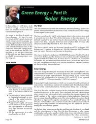
As can be seen in Figure 4, the input amplifier is operating as<br />
an inverting amplifier. The incoming voltage is fed through a<br />
resistor into the negative input <strong>of</strong> the op amp. It is also applied<br />
to the collector <strong>of</strong> the feedback phototransistor.<br />
Figure 4 <strong>Isolation</strong> amplifier (Photovoltaic Operation)<br />
The output <strong>of</strong> the inverting input amplifier, sinks current<br />
through the input diode <strong>of</strong> the optocoupler, whose anode is<br />
pulled up to VCC through a current limiting resistor.<br />
As the input signal is increased, the inverting op amp begins<br />
to sink greater current through the input diode, which in turn<br />
drives the feedback phototransistor into higher conduction.<br />
The photocurrent through the servo control output transistor<br />
is linearly proportional to the input signal.<br />
As the feedback phototransistor conducts it bleeds <strong>of</strong>f current<br />
from the inverting input <strong>of</strong> the op amp, keeping it at 0 volts,<br />
thereby lowering the input signal to the op amp, providing<br />
the negative feedback control.<br />
The output photodiode drives an inverting amplifier, which<br />
inverts and amplifies the already linearized output signal<br />
such that it is properly polarized, and tracks the input signal<br />
as current flows away from the inverting input, into the collector<br />
<strong>of</strong> the output phototransistor.<br />
You will note that I have not attempted to review the math<br />
involved in the preceeding circuit analyses, only the operation<br />
<strong>of</strong> the circuits themselves. This is because Clare has produced<br />
an excellent application note (AN-107). Not only is the<br />
math very simple and straightforward, but it is thoroughly<br />
covered in the App note, which is available for download <strong>of</strong>f<br />
the internet.<br />
Six ranges <strong>of</strong> transfer gain are available for purchase for the<br />
LOC110. Even with factory pre-sorting, small amounts <strong>of</strong><br />
circuit calibration will still likely be required.<br />
Calibration can be accomplished by trimming the amplification<br />
gain resistors <strong>of</strong> the circuit.<br />
Additional Applications:<br />
I have not had the opportunity to cover many applications <strong>of</strong><br />
the LOC110 within the scope <strong>of</strong> this article. The LOC110 can<br />
also be used for modem DAA (Data Access Arrangement)<br />
circuits, where the device can replace the cumbersome isolation<br />
transformer <strong>of</strong> years past.<br />
The LOC110 can also be used in switch mode power supply<br />
designs, cardiac monitoring, isolating voltage to current converters,<br />
and RTD temperature measuring circuits, etc.<br />
You will find LOC11x series devices for sale on the internet<br />
for under $2.00 USD, and they also come with two completely<br />
independent opto-couplers in the same package (LOC21x<br />
series).<br />
An assortment <strong>of</strong> external amplifiers can be used with the<br />
LOC110 including the LM358, LM201, LM1558 and LMC6484.<br />
For high precision/accuracy applications, the AD824 has also<br />
been used. http://www.analog.com/static/imported-files/<br />
data_sheets/AD824.pdf<br />
Conclusion<br />
I would like to thank David Hickle, President <strong>of</strong> Xtel International<br />
for his assistance in the writing <strong>of</strong> this article and<br />
Clare for permission to use graphics (Figures 3 and 4) from<br />
the LOC110 App Note, AN-107.<br />
The LOC series <strong>of</strong> opto-isolators provide low cost, small form<br />
factor, and superior performance over traditional transformer<br />
interface designs, and are readily available from several suppliers.<br />
As always, I have tried to be as accurate as possible within<br />
the scope <strong>of</strong> my column, however, there are several aspects to<br />
this device which I have not had the opportunity to review.<br />
Please read the entire data sheet and application note before<br />
implementing this component into a design.<br />
Until next time,<br />
Take care out there!<br />
Repeatability and Circuit Calibration<br />
Any time a manufacturer produces an electronic component,<br />
they strive for specification consistency from part to part. This<br />
is not always easy to achieve, especially with components<br />
such as opto-isolators, where even the smallest physical<br />
difference can lead to varying performance charactaristics<br />
within a circuit.<br />
In order to compensate for differences in the LOC110, Clare<br />
actually tests and pre-sorts the LOC110 into batches, reflecting<br />
different transfer gain characteristics from various production<br />
runs.<br />
Page 46<br />
<strong>IMSA</strong> Journal