Hand Crank - SUSPA.com
Hand Crank - SUSPA.com
Hand Crank - SUSPA.com

Create successful ePaper yourself
Turn your PDF publications into a flip-book with our unique Google optimized e-Paper software.
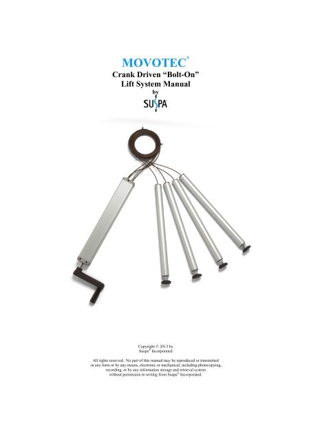
MOVOTEC ®<br />
<strong>Crank</strong> Driven “Bolt-On”<br />
Lift System Manual<br />
by<br />
Copyright © 2013 by<br />
Suspa ® Incorporated<br />
All rights reserved. No part of this manual may be reproduced or transmitted<br />
in any form or by any means, electronic or mechanical, including photocopying,<br />
recording, or by any information storage and retrieval system<br />
without permission in writing from Suspa ® Incorporated.
1<br />
1.0 Table of Contents<br />
2.0 Introduction ................................................................................................................. 2<br />
3.0 Safety Instructions ...................................................................................................... 2<br />
4.0 How it Works............................................................................................................... 4<br />
4.1 Extension Cycle ......................................................................................................... 4<br />
4.2 Retraction Cycle: ....................................................................................................... 5<br />
5.0 Unpacking Instructions .............................................................................................. 5<br />
6.0 Lift System Specifications .......................................................................................... 7<br />
6.1 Lift Cylinder Specifications ....................................................................................... 7<br />
6.2 <strong>Crank</strong> Driven Pump Specifications ........................................................................... 8<br />
6.3 Regulatory Information ............................................................................................. 8<br />
7.0 Installation Instructions ............................................................................................. 9<br />
7.1 System Component Placement .................................................................................. 9<br />
7.2 <strong>Crank</strong> Driven Pump Installation .............................................................................. 10<br />
7.3 Lift Cylinder Installation ......................................................................................... 11<br />
7.4 Hydraulic Tubing Management ............................................................................... 14<br />
7.5 Workstation Leveling .............................................................................................. 14<br />
8.0 Operation Instructions ............................................................................................. 16<br />
8.1 Before Loading the Workstation ............................................................................. 16<br />
8.2 System Extension Cycle .......................................................................................... 18<br />
8.3 System Retraction Cycle ......................................................................................... 18<br />
8.4 Stowing the <strong>Crank</strong> ................................................................................................... 19<br />
9.0 Troubleshooting ........................................................................................................ 20<br />
10.0 Inspection and Maintenance .................................................................................. 21<br />
10.1 Changing Load Conditions .................................................................................... 21<br />
10.2 Contamination ....................................................................................................... 21<br />
10.3 Hydraulic Tubing Damage .................................................................................... 21<br />
11.0 Warranty ................................................................................................................. 22<br />
12.0 Replacement Parts .................................................................................................. 23<br />
13.0 Optional Accessories ............................................................................................... 23<br />
14.0 Disposal .................................................................................................................... 23<br />
15.0 Contact Information ............................................................................................... 23<br />
01/11/13<br />
670- 00017A
2<br />
2.0 Introduction<br />
Thank you for purchasing the Movotec ® <strong>Crank</strong> Driven “Bolt-On” Lift System.<br />
For over twenty years, Movotec ® systems have been used on industrial workbenches,<br />
small machine bases, physical therapy equipment, massage tables, office furniture,<br />
biological and chemical vented hoods, autopsy and necropsy tables, sewing machine<br />
bases, home healthcare beds, packaging equipment, custom yachts, and many other<br />
applications.<br />
3.0 Safety Instructions<br />
READ THE INSTRUCTIONS IN THIS MANUAL BEFORE ATTEMPTING TO<br />
INSTALL, OPERATE, OR SERVICE THIS PRODUCT. FOLLOW THESE<br />
SAFETY INSTRUCTIONS AT ALL TIMES.<br />
This manual contains safety, installation, operation, maintenance, and user service<br />
instructions for the Movotec ® <strong>Crank</strong> Driven “Bolt-On” Lift System. Suspa ® Incorporated<br />
is not responsible for any alteration, misuse, misapplication, or abuse of this product<br />
resulting in property damage, personal injury or death.<br />
FAILURE TO FOLLOW THE INSTRUCTIONS IN THIS<br />
MANUAL COULD RESULT IN PROPERTY DAMAGE,<br />
PERSONAL INJURY OR DEATH.<br />
If you have any questions about the use of this product, the safety practices outlined in<br />
this manual or would like a printed copy of this manual, please contact us (see Section 15<br />
for contact information).<br />
VERIFY SYSTEM SELECTION. Before the installing or operating the system,<br />
please review the application to confirm that the correct Movotec ® Lift System has been<br />
selected. Pay particular attention to the load capacity and adjustment range ratings listed<br />
on the blue product label.<br />
HANDLE COMPONENTS WITH CARE. Do not handle system by the hydraulic<br />
tubing. Keep hydraulic tubing far from heat, sharp edges, and moisture. If hydraulic<br />
tubing is damaged, discontinue use and have the tubing replaced immediately. Do not<br />
ever attempt to repair a damaged hydraulic tubing line.<br />
VISUALLY INSPECT COMPONENTS. Before installing and operating the system,<br />
inspect all <strong>com</strong>ponents for any damage that may have occurred during shipping and<br />
installation. Do not attempt to disassemble system or system <strong>com</strong>ponents for any reason.<br />
If a defective <strong>com</strong>ponent is found, contact Suspa ® Incorporated for repair or replacement.<br />
01/11/13<br />
670- 00017A
3<br />
USE OF TRAINED AND QUALIFIED PERSONNEL System installation, operation,<br />
and repair should only be done by persons having sufficient knowledge of the lift system<br />
and the contents of this manual. In addition, they must have an understanding of all<br />
warnings and precautionary measures noted in these safety instructions.<br />
AVOID HAZARDOUS ENVIRONMENT. Do not operate the system outside. Do not<br />
expose the system to damp or wet conditions. Avoid any chemical or corrosive<br />
environments. Do not operate the system in the presence of flammable solvents,<br />
propellants, and/or explosive materials (i.e. gas, vapor, dust, etc.) Avoid temperatures<br />
outside of the system rated operating temperature range 41 ° to 113 ° F (5 ° to 45 ° C). Do<br />
not subject lift system <strong>com</strong>ponents to vibration and/or impact load conditions.<br />
INSTALLATION SAFEGUARDS. Do not use the system for any purpose other than<br />
its intended function. Before operating system, make sure that the workstation has a<br />
minimum clearance of 2 in. (51mm) from any other object or structure to prevent<br />
pinching or crushing hazards. Do not allow wall, cabinet, electrical lines, hydraulic or<br />
pneumatic lines, or any other fixed structures to obstruct the movement of the<br />
workstation during operation.<br />
KEEP CHILDREN AWAY. It is not re<strong>com</strong>mended that children operate this lift<br />
device. If this device is used by or near children, close supervision is absolutely<br />
necessary.<br />
USE OF ACCESSORIES. Use only spare parts and accessories authorized or supplied<br />
by Suspa ® Incorporated. Do not replace or replenish lift system hydraulic fluid unless the<br />
fluid is supplied by Suspa ® Incorporated.<br />
MAINTENANCE SAFEGUARDS. Prior to performing any maintenance or service on<br />
the device, remove the load from all lift cylinders. The workstation or structure that the<br />
lift system is attached to should be stabilized to prevent personal injury or property<br />
damage during maintenance or service procedures.<br />
RETRACT SYSTEM BEFORE MOVING. To reduce the risk of property damage and<br />
personal injury, always retract the lift system fully before moving the equipment.<br />
UNPLUG BEFORE CLEANING. Retract the lift system before cleaning <strong>com</strong>ponents.<br />
Clean system <strong>com</strong>ponents with a mild soap and water-damped cloth. Do not use<br />
corrosive cleaning agents or high pressure wash systems to clean lift system <strong>com</strong>ponents.<br />
Make sure system is clean and dry before operating the system.<br />
SAVE THIS MANUAL FOR FUTURE REFERENCE.<br />
01/11/13<br />
670- 00017A
4<br />
4.0 How it Works<br />
Movotec ® <strong>Crank</strong> Driven “Bolt-On” Lift Systems are <strong>com</strong>prised of three major <strong>com</strong>ponent<br />
subsystems; the crank, the pump, and the lift cylinders. This section will explain how<br />
each subsystem works together to make the lift system extend and retract.<br />
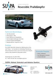
4.1 Extension Cycle<br />
Movotec ® <strong>Crank</strong> Driven Schematic<br />
The crank is mechanically coupled to the pump leadscrew shaft. When the crank is<br />
rotated in a clockwise (CW) direction, the leadscrew shaft rotates in the same (CW)<br />
direction. As the crank continues to rotate in a (CW) direction, the threaded pusherblock<br />
moves up the leadscrew in the direction of arrow “A”. This action drives fluid from the<br />
pressure elements, through the hydraulic tubing, and into the lift cylinders causing them<br />
to extend. As the cylinder load increases, the force required to rotate the crank increases.<br />
Generally speaking, the crank force required to extend the system will always be greater<br />
than the crank force required to retract the system. It is also important to note that when<br />
01/11/13<br />
670- 00017A
5<br />
the pump has reached its upper limit, the user will feel increased resistance at the crank<br />
handle.<br />
4.2 Retraction Cycle: (Refer to Movotec ® <strong>Crank</strong> Driven Schematic on page 6)<br />
The crank is mechanically coupled to the pump leadscrew shaft. When the crank is<br />
rotated in a counter-clockwise (CCW) direction, the leadscrew shaft rotates in the same<br />
(CCW) direction. As the crank continues to rotate in a (CCW) direction, the threaded<br />
pusherblock moves down the leadscrew in the direction of arrow “B”. As long as there is<br />
sufficient load on the lift cylinder piston rods, the fluid in the lift cylinders flows back<br />
through the hydraulic tubing and into the pressure elements. It is important to note that<br />
the user will feel increased resistance at the crank handle when the pump has reached its<br />
lower limit.<br />
5.0 Unpacking Instructions<br />
The system <strong>com</strong>es packaged in a cardboard carton. To unpack the system:<br />
• Check the carton label to confirm that you have received the correct system; open<br />
the carton and remove packaging material.<br />
• Carefully remove the system from the carton, and verify all <strong>com</strong>ponents are<br />
present (reference chart below), and that the correct lift system was received.<br />
Do not handle the lift cylinders and motorized pump by the hydraulic tubing. Incorrect<br />
handling of hydraulic tubing could weaken the tubing material and system tubing<br />
connections.<br />
DAMAGE TO TUBING OR TUBING CONNECTIONS<br />
COULD CAUSE FLUID LOSS AND UNCONTROLLED<br />
DESCENT OF THE WORK-SURFACE.<br />
01/11/13<br />
670- 00017A
6<br />
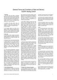
• Verify that all of the listed <strong>com</strong>ponents are present; carton should contain:<br />
System Component<br />
Quantity<br />
(A) <strong>Crank</strong> Driven Pump 1<br />
(B) Lift Cylinders 4<br />
(C) Drill Templates 4<br />
(D) Cable Ties 8<br />
(E) Mounting Clips 8<br />
• If the lift system is damaged or any <strong>com</strong>ponent is missing, please contact<br />
Suspa ® Incorporated to resolve the issue.<br />
• Dispose of the all packaging materials in an ecologically sound manner; if<br />
uncertainty exists with regards to disposal / recycling details, please contact<br />
Suspa ® Incorporated.<br />
01/11/13<br />
670- 00017A
7<br />
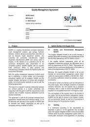
6.0 Lift System Specifications<br />
The “A”, “B”, “X”, and “Y” dimensions shown in the table and drawings below vary<br />
depending on the system lift capacity and the adjustment range of the selected system.<br />
Lift System Adjustment System Lift CB "Bolt-On" Cylinder <strong>Crank</strong> Driven Pump<br />
Part Range Capacity "A" "B" "X" "Y"<br />
Number (in/mm) (lb/kg) (in/mm) (in/mm) (in/mm) (in/mm)<br />
MLS-00001 6.1 / 155 750 / 340 10.2 / 258.5 6.49 / 165 11.50 / 292 10.87 / 276<br />
MLS-00002 7.7 / 195 750 / 340 13.1 / 333.5 9.45 / 240 13.86 / 352 13.23 / 336<br />
MLS-00003 11.8 / 300 750 / 340 18.3 / 463.5 13.39 / 340 18.58 / 472 17.95 / 456<br />
MLS-00004 15.7 / 400 750 / 340 22.0 / 558.5 13.39 / 340 23.39 / 594 22.76 / 578<br />
MLS-00005 5.9 / 150 1000 / 454 10.2 / 258.5 6.49 / 165 13.86 / 352 13.23 / 336<br />
MLS-00006 9.1 / 230 1000 / 454 18.3 / 463.5 13.39 / 340 16.22 / 412 15.59 / 396<br />
MLS-00007 12.0 / 305 1000 / 454 18.3 / 463.5 13.39 / 340 23.39 / 594 22.76 / 578<br />
MLS-00008 15.7 / 400 1000 / 454 22.0 / 558.5 13.39 / 340 28.43 / 722 27.80 / 706<br />
6.1 Lift Cylinder Specifications<br />
CB4xx cylinders are rated for a maximum load of 250lb (113.4kg) each.<br />
01/11/13<br />
670- 00017A
8<br />
6.2 <strong>Crank</strong> Driven Pump Specifications (Refer to Chart on Page X for “X” and “Y”<br />
dimensions)<br />
6.3 Regulatory Information<br />
RoHS Directive (2002/95/EC)<br />
Suspa ® Incorporated has examined all of the materials and processes utilized in the<br />
production of Movotec ® lift systems and has determined that this product is in <strong>com</strong>pliance<br />
with the European Union RoHS Directive 2002/95/EC.<br />
01/11/13<br />
670- 00017A
9<br />
7.0 Installation Instructions<br />
FOLLOW ALL SAFETY INSTRUCTIONS CONTAINED<br />
IN SECTION 3.0 OF THIS MANUAL BEFORE<br />
INSTALLING THIS PRODUCT. FAILURE TO<br />
FOLLOW THE INSTRUCTIONS IN THIS MANUAL<br />
COULD RESULT IN PROPERTY DAMAGE,<br />
PERSONAL INJURY OR DEATH.<br />
7.1 System Component Placement<br />
Movotec ® <strong>Crank</strong> Driven “Bolt-On” Lift System <strong>com</strong>ponents are physically linked<br />
together with hydraulic tubing. Therefore, it is very important to make sure that the<br />
system <strong>com</strong>ponents are located on the workstation so that each <strong>com</strong>ponent can be<br />
installed safely without damaging the hydraulic tubing. It is also important to make sure<br />
that the crank has enough clearance to rotate freely beyond the work surface.<br />
7.1.1 <strong>Crank</strong> Driven Pump Placement - The crank driven pump can be installed<br />
in any orientation, however it is re<strong>com</strong>mended to mount the unit horizontally.<br />
The pump should be installed so that there is enough hydraulic tubing to reach<br />
each lift cylinder and enough clearance for the minimum hydraulic tubing bend<br />
radius of 2 in. (51mm) to be maintained. The crank should be located near the<br />
edge of the work-surface. Suspa ® Incorporated offers other cranks and crank<br />
hardware options which can be purchased on our website at http://movotec.<strong>com</strong> .<br />
7.1.2 Lift Cylinder Placement – The lift cylinders should be located on the<br />
workstation so that the load on the system is balanced. Lift cylinders must also be<br />
oriented vertically and parallel to one another to prevent cylinder binding during<br />
extension and retraction cycles. Suspa ® Incorporated offers an assortment of<br />
brackets to reduce the number of holes to be drilled for lift cylinder mounting and<br />
to facilitate system installation. These cylinder mounting brackets can be<br />
purchased on our website at http://movotec.<strong>com</strong> .<br />
7.1.3 Hydraulic Tubing Placement – Hydraulic tubing must be kept away from<br />
sharp edges and moving parts. Contact with moisture and heat must also be<br />
avoided. Hydraulic tubing should fixed to the workstation or structure using the<br />
cable ties and mounting clips provided. Additional cable ties and mounting clips<br />
can be purchased on our website at http://movotec.<strong>com</strong> .<br />
01/11/13<br />
670- 00017A
10<br />
7.2 <strong>Crank</strong> Driven Pump Installation<br />
• If possible, orient workstation as shown for ease of <strong>com</strong>ponent placement and<br />
installation.<br />
• Place crank driven pump in the desired location, making sure sufficient clearance<br />
exists for the crank to rotate freely beyond the work-surface.<br />
• Mark and prepare three holes in the locations provided in the pump front and rear<br />
mounting plates.<br />
01/11/13<br />
670- 00017A
11<br />
• Mount the crank driven pump to the work-surface. Please note that mounting<br />
screws are not provided with system.<br />
• Check mounting screws to ensure that the unit is tightly secured.<br />
7.3 Lift Cylinder Installation<br />
• Unwrap lift cylinders and drilling templates from bubble wrapping. Dispose of<br />
bubble wrapping material in an ecologically sound manner.<br />
• Thoroughly clean all workstation leg surfaces to ensure the cylinder drilling<br />
templates will adhere. Apply the drilling templates parallel to the workstation leg<br />
surfaces, making sure that the templates are oriented correctly.<br />
01/11/13<br />
670- 00017A
12<br />
• Please note that the drilling templates are shown upside down due to the<br />
orientation of the workstation.<br />
NOTICE<br />
Lift cylinder mounting hole locations vary depending<br />
upon the lift cylinder model number. The lift cylinder<br />
model number can be found on the product label.<br />
“Bolt-On” lift cylinder model numbers begin with “CB”<br />
(i.e. CB431).<br />
Lift cylinder mounting instructions can also be found<br />
printed on the drilling templates provided with the system.<br />
• Drill (4) - 6mm holes in the appropriate locations indicated on each drill<br />
templates.<br />
• Select cylinder mounting screws with a property class of 8.8 or greater.<br />
01/11/13<br />
670- 00017A
13<br />
NOTICE<br />
To avoid lift cylinder damage, the screw depth must not<br />
exceed 7mm (0.27 in.) into the lift cylinder housing as<br />
shown below.<br />
• Install each cylinder to the workstation frame using (4) - M5 screws of the<br />
appropriate length. Suspa ® Incorporated re<strong>com</strong>mends a lift cylinder mounting<br />
screw thread engagement of 0.196-.0275in. (5-7mm).<br />
• Ensure that there is enough flexible hydraulic tubing to reach each workstation leg<br />
without putting any tension on the tubing and while maintaining the minimum<br />
flexible tubing bend radius of 2in. (51mm). Each system is shipped with<br />
hydraulic tubing cut-to-length and assembled to the unit, (2) lengths at 8.2 ft.<br />
(2.5m), and (2) lengths at 10.2 ft. (3.1m).<br />
• Check the lift cylinder mounting screws to ensure that they are tightly secured to<br />
the workstation. Take special care not to over tighten lift cylinder mounting<br />
screws. Suspa ® Incorporated re<strong>com</strong>mends a lift cylinder mounting screw<br />
tightening torque of 4.0-4.5 N-m (35-40 lb-in).<br />
01/11/13<br />
670- 00017A
14<br />
7.4 Hydraulic Tubing Management<br />
• Coil up excess hydraulic flexible tubing into approximately 6 in. (150mm)<br />
diameter coil(s) and attach to the workstation using the mounting clips and/or<br />
cable ties. Take special care not to damage flexible tubing during this operation.<br />
• While it is re<strong>com</strong>mended to coil up excess tubing when hydraulic tubing lengths<br />
are too long, the lines can be shortened. Contact Suspa ® Incorporated for detailed<br />
Movotec ® Tube Shortening Instructions.<br />
• If hydraulic tubing lengths are too short, it is only possible to make the tubing<br />
lengths longer by replacing the line, using a Movotec ® Refill Kit. Contact Suspa ®<br />
Incorporated for a more information and instructions.<br />
• Check flexible tubing to ensure it is secured to the workstation and that no<br />
damage has been sustained during this operation.<br />
7.5 Workstation Leveling<br />
• Thread glides into all lift cylinders until the glide threads are fully engaged as<br />
shown. This step will provide a good starting point for leveling the workstation.<br />
01/11/13<br />
670- 00017A
15<br />
• Re-orient the workstation so that the glides are in contact with the floor as shown.<br />
NOTICE<br />
To prevent damage from occurring to the system, take<br />
special care not to drop the workstation onto the lift<br />
cylinders<br />
• Place a level on the top of the work-surface. Unthread glide(s) from the lift<br />
cylinder(s) as needed to achieve a level work-surface. Once the workstation is<br />
level, tighten the lock nut on all four glides to ensure the workstation will remain<br />
level during use.<br />
01/11/13<br />
670- 00017A
16<br />
8.0 Operation Instructions<br />
FOLLOW ALL SAFETY INSTRUCTIONS CONTAINED<br />
IN SECTION 3.0 OF THIS MANUAL BEFORE<br />
OPERATING THIS PRODUCT. FAILURE TO<br />
FOLLOW THE INSTRUCTIONS IN THIS MANUAL<br />
COULD RESULT IN PROPERTY DAMAGE,<br />
PERSONAL INJURY OR DEATH.<br />
Movotec ® systems can lift relatively large loads, lasting for many years, as long as they<br />
are installed and used correctly. The Movotec ® <strong>Crank</strong> Driven “Bolt-On” Lift System is<br />
not intended for continuous cycling or for applications requiring precision height<br />
adjustment.<br />
NOTICE<br />
The Movotec ® lift system is single-acting and will require a<br />
minimum load of 35 lb (15.9 kg) per cylinder for even lift<br />
system retraction.<br />
8.1 Before Loading the Workstation<br />
• Check all hydraulic connections.<br />
• Check for damage to flexible hydraulic tubing that may have occurred while<br />
unpacking or installing the system.<br />
• Check all system <strong>com</strong>ponents to ensure that they are tightly secured to the work<br />
station.<br />
• Confirm that a minimum load of 35 lb (15.9 kg) per cylinder is present for even<br />
lift system retraction.<br />
• Confirm the maximum system load is not being exceeded. The maximum system<br />
load is the total load including the workstation being lifted and anything on top of<br />
the work-surface.<br />
01/11/13<br />
670- 00017A
17<br />
If the lift system does not operate as explained in Section 4.0<br />
of this manual, remove the load from the system immediately<br />
and contact Suspa ® Incorporated technical support.<br />
If technical support is needed, or any questions exist before operation, system<br />
information can be found using the product labels located on the side of the pump<br />
(reference photographs below).<br />
NOTICE<br />
Do not dismantle the system unless authorized by Suspa ®<br />
Incorporated. Attempting to repair the system or system<br />
<strong>com</strong>ponents without authorization from Suspa ® Incorporated<br />
voids the warranty.<br />
01/11/13<br />
670- 00017A
18<br />
8.2 System Extension Cycle<br />
Rotate crank in the clockwise (CW) direction. Continue rotating the crank in the (CW)<br />
direction until the workstation has reached the desired height or the upper limit is<br />
reached.<br />
8.3 System Retraction Cycle<br />
Rotate crank in the counter-clockwise (CCW) direction. Continue rotating the crank in<br />
the (CCW) direction until the workstation has reached the desired height or the lower<br />
limit is reached.<br />
01/11/13<br />
670- 00017A
19<br />
8.4 Stowing the <strong>Crank</strong><br />
When not in use, the folding handle can easily be stowed inside the crank body.<br />
Pull crank grip outward until crank mechanism begins to fold.<br />
01/11/13<br />
670- 00017A
20<br />
9.0 Troubleshooting<br />
Many system problems can be attributed to system load conditions or incorrect mounting<br />
hardware usage. In most cases, problems can be solved by reviewing the following<br />
possible system problems, possible causes, and implementing the re<strong>com</strong>mended<br />
solutions.<br />
Problem: <strong>Crank</strong> turns but does not extend or retract system.<br />
Possible Causes<br />
Re<strong>com</strong>mended Solutions<br />
<strong>Crank</strong> not fully engaged<br />
Ensure crank handle is fully installed on to pump<br />
shaft.<br />
Broken Pusher Block Contact Suspa ® Incorporated for replacement pump.<br />
Problem: <strong>Crank</strong> is difficult to turn.<br />
Possible Causes<br />
Upper or Lower Limit Reached<br />
Workstation movement is<br />
obstructed by fixed object(s)<br />
System Load is High or Load<br />
Rating is exceeded<br />
Re<strong>com</strong>mended Solutions<br />
Stop rotating crank.<br />
Provide clearance between workstation and<br />
obstruction.<br />
Verify system load does not exceed rating and<br />
remove weight as needed.<br />
Problem: Uneven lift cylinder retraction.<br />
Possible Causes<br />
Re<strong>com</strong>mended Solutions<br />
Insufficient Lift Cylinder Load<br />
Add load to system. Contact Suspa ® Incorporated<br />
for tube shortening instructions.<br />
Cylinder Mounting Screws Too<br />
Long<br />
Reduce cylinder mounting screw length.<br />
Flexible Tubing Lengths Too<br />
Long<br />
Contact Suspa ® Incorporated for tube shortening<br />
instructions.<br />
01/11/13<br />
670- 00017A
21<br />
10.0 Inspection and Maintenance<br />
FOLLOW ALL SAFETY INSTRUCTIONS CONTAINED<br />
IN SECTION 3.0 OF THIS MANUAL BEFORE<br />
PERFORMING INSPECTION AND MAINTENANCE<br />
PROCEDURES ON THIS PRODUCT. FAILURE TO<br />
FOLLOW THE INSTRUCTIONS IN THIS MANUAL<br />
COULD RESULT IN PROPERTY DAMAGE,<br />
PERSONAL INJURY OR DEATH.<br />
The Movotec ® <strong>Crank</strong> Driven “Bolt-On” Lift System should be inspected regularly to<br />
detect any condition which has or may lead to excessive <strong>com</strong>ponent wear or premature<br />
failure. Special attention should be given to the following possible causes of system<br />
failure.<br />
10.1 Changing Load Conditions<br />
Overload conditions should be promptly corrected to prevent premature wear of<br />
mechanical <strong>com</strong>ponents. This will also prevent overheating and premature failure of<br />
electrical <strong>com</strong>ponents.<br />
10.2 Contamination<br />
Although surgical cleanliness is not required, ordinary cleaning practices will pay off in<br />
increased service life of the lift system. Dust and dirt can restrict ventilation for electrical<br />
<strong>com</strong>ponents and cause wear in moving <strong>com</strong>ponents such as shafts and bearings. An<br />
attempt should be made to keep the system <strong>com</strong>ponents reasonably clean throughout their<br />
useable service life.<br />
10.3 Hydraulic Tubing Damage<br />
Check the hydraulic tubing for visible signs of aging and wear. Replacement of damaged<br />
hydraulic tubing will prevent future breakdowns and possible injury to personnel.<br />
01/11/13<br />
670- 00017A
22<br />
11.0 Warranty<br />
Suspa ® Incorporated warrants that if the Movotec ® <strong>Crank</strong> Driven “Bolt-On” Lift System<br />
has been properly installed and not subject to abuse or misuse and proves to be defective<br />
(as defined below) within the Applicable Warranty Period after the date of manufacture<br />
of the item by Suspa ® Incorporated or, if applicable, by Suspa ® Incorporated’s supplier<br />
and if the Buyer returns the item to Seller within that period, F.O.B. Suspa ®<br />
Incorporated’s plant in Grand Rapids, Michigan, then Suspa ® Incorporated shall, at<br />
Suspa ® Incorporated’s option, either repair of replace the defective item, at Suspa ®<br />
Incorporated’s expense. If Suspa ® Incorporated fails to repair or replace a defective item<br />
within a reasonable time, then Suspa ® Incorporated shall be liable to the Buyer for the<br />
lesser of (1) the reasonable costs of repair or replacement by a third party or (2) that part<br />
of the purchase price of the defective goods that the Buyer shall have paid, but the Buyer<br />
shall not obtain repair or replacement by a third party without giving Suspa ® Incorporated<br />
at least fifteen (15) days prior written notice, during which time Suspa ® Incorporated may<br />
repair or replace the defective item. An item shall be considered “defective” if Suspa ®<br />
Incorporated finds that it is defective in materials or workmanship and if the defect<br />
materially impairs the value of the goods to the Buyer, except that if the Buyer shall have<br />
approved drawings of, or specifications for, or production samples of the goods, then the<br />
goods shall not be defective to the extent that they conform to the drawings,<br />
specifications, or samples. This paragraph sets forth the Buyer’s sole and exclusive<br />
remedies for any defect in the goods. The Applicable Warranty Period for the Movotec ®<br />
<strong>Crank</strong> Driven “Bolt-On” Lift System is two years.<br />
EXCEPT AS STATED IN THE PREVIOUS PARAGRAPH, <strong>SUSPA</strong> ®<br />
INCORPORATED DOES NOT MAKE ANY WARRANTY AS TO THE GOODS<br />
AND, IN PARTICULAR, DOES NOT MAKE ANY WARRANTY OF<br />
MERCHANTABILITY OR FITNESS FOR ANY PARTICULAR PURPOSE, AND<br />
THE BUYER IS SOLELY RESPONSIBLE FOR DETERMINING THE PROPER<br />
APPLICATION AND USE OF THE GOODS. Suspa ® Incorporated shall not have any<br />
tort liability to the Buyer with respect to any of the goods and shall not be liable for<br />
consequential or incidental damages that arise from any product defect, delay,<br />
nondelivery, or other breach. The Buyer shall not have any right of rejection or of<br />
revocation of acceptance of Movotec ® <strong>Crank</strong> Driven “Bolt-On” Lift System products.<br />
If you have any questions regarding the warranty or believe that you have received a<br />
defective <strong>com</strong>ponent, please contact Suspa ® Incorporated.<br />
01/11/13<br />
670- 00017A
23<br />
12.0 Replacement Parts<br />
Contact Suspa ® Incorporated if the system has sustained any damage during shipping or<br />
installation. Suspa ® Incorporated can help determine whether the system can be serviced<br />
with replacement parts or if the entire system should be replaced. Before contacting<br />
Suspa ® Incorporated, please have the system part number, system model number, and<br />
date code ready, which can be found on the blue product label affixed to the side of the<br />
pump (as shown below):<br />
13.0 Optional Accessories<br />
Suspa ® Incorporated offers many optional accessories for customizing Movotec ® <strong>Crank</strong><br />
Driven “Bolt-On” Lift Systems which include:<br />
- Lift cylinder mounting brackets<br />
- Special folding cranks<br />
- Hydraulic tube shortening instructions<br />
- System refill kits<br />
Please contact Suspa ® Incorporated or view our website for more detailed information.<br />
14.0 Disposal<br />
Dispose of the lift system <strong>com</strong>ponents in an ecologically sound manner, separating<br />
plastic, mechanical <strong>com</strong>ponents, and hydraulic fluid. Fluid disposal instructions for<br />
Movotec ® NT15 hydraulic fluid can be found on our Material Safety Data Sheet (MSDS)<br />
document which is available upon request.<br />
15.0 Contact Information<br />
<strong>SUSPA</strong> Incorporated<br />
3970 Roger B. Chaffee Drive SE<br />
Grand Rapids, MI 49548-3497<br />
Phone: (616) 241-4200<br />
Fax: (616) 241-4347<br />
www.suspa.<strong>com</strong><br />
01/11/13<br />
670- 00017A