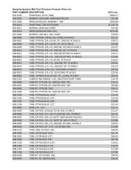
Teejet Catalog 51 - Farmco Distributing Inc
Teejet Catalog 51 - Farmco Distributing Inc
Teejet Catalog 51 - Farmco Distributing Inc

You also want an ePaper? Increase the reach of your titles
YUMPU automatically turns print PDFs into web optimized ePapers that Google loves.
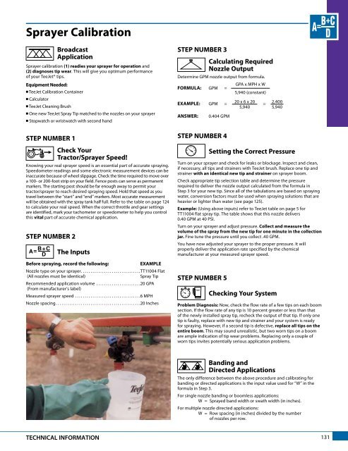
Sprayer Calibration<br />
Broadcast<br />
Application<br />
Sprayer calibration (1) readies your sprayer for operation and<br />
(2) diagnoses tip wear. This will give you optimum performance<br />
of your TeeJet® tips.<br />
Equipment Needed:<br />
n TeeJet Calibration Container<br />
n Calculator<br />
n TeeJet Cleaning Brush<br />
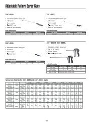
n One new TeeJet Spray Tip matched to the nozzles on your sprayer<br />
n Stopwatch or wristwatch with second hand<br />
STEP NUMBER 1<br />
Check Your<br />
Tractor/Sprayer Speed!<br />
Knowing your real sprayer speed is an essential part of accurate spraying.<br />
Speedometer readings and some electronic measurement devices can be<br />
inaccurate because of wheel slippage. Check the time required to move over<br />
a 100- or 200-foot strip on your field. Fence posts can serve as permanent<br />
markers. The starting post should be far enough away to permit your<br />
tractor/sprayer to reach desired spraying speed. Hold that speed as you<br />
travel between the “start” and “end” markers. Most accurate measurement<br />
will be obtained with the spray tank half full. Refer to the table on page 124<br />
to calculate your real speed. When the correct throttle and gear settings<br />
are identified, mark your tachometer or speedometer to help you control<br />
this vital part of accurate chemical application.<br />
STEP NUMBER 2<br />
The Inputs<br />
Before spraying, record the following:<br />
EXAMPLE<br />
Nozzle type on your sprayer...............................TT11004 Flat<br />
(All nozzles must be identical)<br />
Spray Tip<br />
Recommended application volume .......................20 GPA<br />
(From manufacturer’s label)<br />
Measured sprayer speed ..................................6 MPH<br />
Nozzle spacing............................................20 <strong>Inc</strong>hes<br />
STEP NUMBER 3<br />
Calculating Required<br />
Nozzle Output<br />
Determine GPM nozzle output from formula.<br />
GPA x MPH x W<br />
FORMULA: GPM =<br />
5,940 (constant)<br />
20 x 6 x 20 2,400<br />
EXAMPLE: GPM = =<br />
5,940 5,940<br />
ANSWER:<br />
0.404 GPM<br />
STEP NUMBER 4<br />
Setting the Correct Pressure<br />
Turn on your sprayer and check for leaks or blockage. Inspect and clean,<br />
if necessary, all tips and strainers with TeeJet brush. Replace one tip and<br />
strainer with an identical new tip and strainer on sprayer boom.<br />
Check appropriate tip selection table and determine the pressure<br />
required to deliver the nozzle output calculated from the formula in<br />
Step 3 for your new tip. Since all of the tabulations are based on spraying<br />
water, conversion factors must be used when spraying solutions that are<br />
heavier or lighter than water (see page 125).<br />
Example: (Using above inputs) refer to TeeJet table on page 5 for<br />
TT11004 flat spray tip. The table shows that this nozzle delivers<br />
0.40 GPM at 40 PSI.<br />
Turn on your sprayer and adjust pressure. Collect and measure the<br />
volume of the spray from the new tip for one minute in the collection<br />
jar. Fine tune the pressure until you collect .40 GPM.<br />
You have now adjusted your sprayer to the proper pressure. It will<br />
properly deliver the application rate specified by the chemical<br />
manufacturer at your measured sprayer speed.<br />
STEP NUMBER 5<br />
Checking Your System<br />
Problem Diagnosis: Now, check the flow rate of a few tips on each boom<br />
section. If the flow rate of any tip is 10 percent greater or less than that<br />
of the newly installed spray tip, recheck the output of that tip. If only one<br />
tip is faulty, replace with new tip and strainer and your system is ready<br />
for spraying. However, if a second tip is defective, replace all tips on the<br />
entire boom. This may sound unrealistic, but two worn tips on a boom<br />
are ample indication of tip wear problems. Replacing only a couple of<br />
worn tips invites potentially serious application problems.<br />
Banding and<br />
Directed Applications<br />
The only difference between the above procedure and calibrating for<br />
banding or directed applications is the input value used for “W” in the<br />
formula in Step 3.<br />
For single nozzle banding or boomless applications:<br />
W = Sprayed band width or swath width (in inches).<br />
For multiple nozzle directed applications:<br />
W = Row spacing (in inches) divided by the number<br />
of nozzles per row.<br />
TECHNICAL INFORMATION<br />
131