Teejet Catalog 51 - Farmco Distributing Inc
Teejet Catalog 51 - Farmco Distributing Inc
Teejet Catalog 51 - Farmco Distributing Inc

Create successful ePaper yourself
Turn your PDF publications into a flip-book with our unique Google optimized e-Paper software.
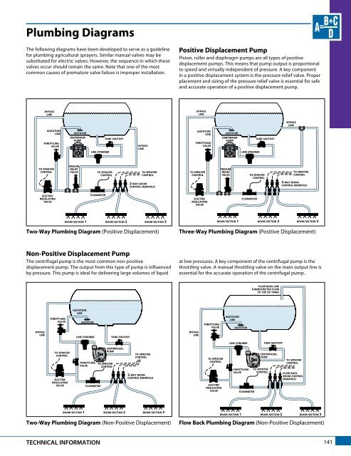
Plumbing Diagrams<br />
The following diagrams have been developed to serve as a guideline<br />
for plumbing agricultural sprayers. Similar manual valves may be<br />
substituted for electric valves. However, the sequence in which these<br />
valves occur should remain the same. Note that one of the most<br />
common causes of premature valve failure is improper installation.<br />
Positive Displacement Pump<br />
Piston, roller and diaphragm pumps are all types of positive<br />
displacement pumps. This means that pump output is proportional<br />
to speed and virtually independent of pressure. A key component<br />
in a positive displacement system is the pressure relief valve. Proper<br />
placement and sizing of the pressure relief valve is essential for safe<br />
and accurate operation of a positive displacement pump.<br />
bypass<br />
line<br />
bypass<br />
line<br />
bypass<br />
line<br />
agitation<br />
line<br />
throttling<br />
valve<br />
agitator<br />
diaphragm<br />
pump<br />
line strainer<br />
tank shutoff<br />
bypass<br />
line<br />
agitation<br />
line<br />
throttling<br />
valve<br />
agitator<br />
diaphragm<br />
pump<br />
line strainer<br />
tank shutoff<br />
to sprayer<br />
control<br />
pressure<br />
relief<br />
valve<br />
to sprayer<br />
control<br />
to sprayer<br />
control<br />
2-way boom<br />
control manifold<br />
to sprayer<br />
control<br />
pressure<br />
relief<br />
valve<br />
to sprayer<br />
control<br />
to sprayer<br />
control<br />
3-way boom<br />
control manifold<br />
electric<br />
regulating<br />
valve<br />
flowmeter<br />
electric<br />
regulating<br />
valve<br />
flowmeter<br />
boom section 1<br />
boom section 2<br />
boom section 3<br />
boom section 1<br />
boom section 2<br />
boom section 3<br />
Two-Way Plumbing Diagram (Positive Displacement)<br />
Three-Way Plumbing Diagram (Positive Displacement)<br />
Non-Positive Displacement Pump<br />
The centrifugal pump is the most common non-positive<br />
displacement pump. The output from this type of pump is influenced<br />
by pressure. This pump is ideal for delivering large volumes of liquid<br />
at low pressures. A key component of the centrifugal pump is the<br />
throttling valve. A manual throttling valve on the main output line is<br />
essential for the accurate operation of the centrifugal pump.<br />
flow back line<br />
(unrestricted flow<br />
to top of tank)<br />
bypass<br />
line<br />
throttling<br />
valve<br />
agitation<br />
line<br />
agitator<br />
line strainer<br />
tank shutoff<br />
bypass<br />
line<br />
throttling<br />
valve<br />
agitation<br />
line<br />
agitator<br />
line strainer<br />
tank shutoff<br />
to sprayer<br />
control<br />
electric<br />
regulating<br />
valve<br />
throttling<br />
valve<br />
flowmeter<br />
centrifugal<br />
pump<br />
to sprayer<br />
control<br />
to sprayer<br />
control<br />
2-way boom<br />
control manifold<br />
to sprayer<br />
control<br />
electric<br />
regulating<br />
valve<br />
throttling<br />
valve<br />
flowmeter<br />
centrifugal<br />
pump<br />
to sprayer<br />
control<br />
to sprayer<br />
control<br />
flow back<br />
boom control<br />
manifold<br />
boom section 1<br />
boom section 2<br />
boom section 3<br />
Two-Way Plumbing Diagram (Non-Positive Displacement)<br />
boom section 1<br />
boom section 2<br />
boom section 3<br />
Flow Back Plumbing Diagram (Non-Positive Displacement)<br />
TECHNICAL INFORMATION<br />
141