(R410A).
(R410A).
(R410A).
- No tags were found...

You also want an ePaper? Increase the reach of your titles
YUMPU automatically turns print PDFs into web optimized ePapers that Google loves.
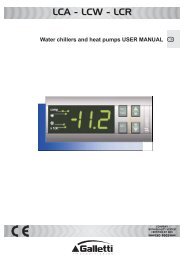
SERVICE<br />
INSTRUCTION<br />
SPLIT TYPE<br />
ROOM AIR CONDITIONER<br />
FLOOR type<br />
INVERTER<br />
Models Indoor unit Outdoor unit<br />
AG * V09LAC<br />
AG * V12LAC<br />
AG * V14LAC<br />
AO * V09LAC<br />
AO * V12LAC<br />
AO * V14LAC<br />
<strong>R410A</strong>
CONTENTS<br />
1. SPECIFICATION<br />
AG*V09/ 12/ 14LAC, AO*V09/ 12/ 14LAC....................................................................... 01-01<br />
2. DIMENSIONS<br />
AG*V09/ 12LAC, AO*V09/ 12LAC................................................................................... 02-01<br />
AG*V14LAC, AO*V14LAC............................................................................................... 02-02<br />
3. REFRIGERANT SYSTEM DIAGRAM<br />
AG*V09/ 12/ 14LAC, AO*V09/ 12/ 14LAC.......................................................................<br />
03-01<br />
4. CIRCUIT DIAGRAM<br />
AG*V09/ 12LAC, AO*V09/ 12LAC................................................................................... 04-01<br />
AG*V14LAC, AO*V14LAC............................................................................................... 04-02<br />
5. DESCRIPTION OF EACH CONTROL OPERATION<br />
1. COOLING OPERATION.............................................................................................. 05-01<br />
2. HEATING OPERATION..............................................................................................<br />
3. DRY OPERATION......................................................................................................<br />
4. AUTO CHANGEOVER OPERATION.........................................................................<br />
5. INDOOR FAN CONTROL...........................................................................................<br />
6. OUTDOOR FAN CONTROL.......................................................................................<br />
7. LOUVER CONTROL...................................................................................................<br />
8. COMPRESSOR CONTROL........................................................................................<br />
9. TIMER OPERATION CONTROL................................................................................<br />
10. ELECTRONIC EXPANSION VALVE CONTROL........................................................<br />
11. TEST OPERATION CONTROL.................................................................................. 05-12<br />
12. PREVENT TO RESTART FOR 3 MINUTES ( 3 MINUTES ST )................................ 05-12<br />
13. FOUR-WAY VALVE EXTENSION SELECT...............................................................<br />
14. AUTO RESTART........................................................................................................<br />
15. MANUAL AUTO OPERATION ( Indoor unit body operation ).....................................<br />
16. FORCED COOLING OPERATION............................................................................<br />
17. COMPRESSOR PREHEATING.................................................................................. 05-13<br />
18. COIL DRY OPEARTION CONTROL..........................................................................<br />
19. DEFROST OPERATION CONTROL..........................................................................<br />
20. OFF DEFROST OPERATION CONTROL..................................................................<br />
21. AIR OUTLET SELECTION (DAMPER CONTROL)....................................................<br />
05-02<br />
05-03<br />
05-04<br />
05-05<br />
05-07<br />
05-08<br />
05-09<br />
05-10<br />
05-12<br />
05-12<br />
05-12<br />
05-13<br />
05-13<br />
05-13<br />
05-14<br />
05-16<br />
05-17<br />
22. 10°C HEAT OPERATION........................................................................................... 05-18<br />
23. VARIOUS PROTECTIONS......................................................................................... 05-19
6. REFRIGERANT CAUTION -<strong>R410A</strong>-<br />
1. <strong>R410A</strong> TOOLS............................................................................................................ 06-01<br />
2. PRECAUTION FOR INSTALLATION......................................................................... 06-02<br />
3. PRECAUTION FOR SERVICING............................................................................... 06-04<br />
4. NEW REFRIGERANT <strong>R410A</strong>..................................................................................... 06-05<br />
5. DEFFERENCE FROM CONVENTIONAL MODEL(R22) AND PRECAUTIONS........ 06-08<br />
7. TROUBLE SHOOTING<br />
1. WHEN THE UNIT DOES NOT OPERATE AT ALL.................................................... 07-01<br />
2. SELF DIAGNOSIS FUNCTION.................................................................................. 07-02<br />
3. SELF-DIAGNOSIS FUNCTION AND CHECKING POINTS....................................... 07-03<br />
4. SERIAL SIGNAL DIAGNOSIS.................................................................................... 07-08<br />
5. IPM PROTECTION..................................................................................................... 07-09<br />
6. TROUBLE SHOOTING OF REFRIGERANT CYCLE................................................. 07-10<br />
8. APPENDING DATA<br />
1. JUMPER SETTING OF INDOOR UNIT AND OUTDOOR UNIT................................ 08-01<br />
2. OUTDOOR UNIT PRESSURE VALUE AND TOTAL ELECTRIC<br />
CURRENT CURVE................................................................................................... 08-02<br />
3. THERMISTOR RESISTANCE VALUES..................................................................... 08-06<br />
9. REPLACEMENT PARTS<br />
1. DISASSEMBLY ILLUSTRATION & PARTS LIST......................................................<br />
2. DISASSEMBLY PROCESS ......................................................................................<br />
09-01<br />
09-13<br />
10. INSTALLATION MANUAL
<strong>R410A</strong><br />
FLOOR type<br />
INVERTER<br />
1 . SPECIFICATIONS
SPECIFICATIONS<br />
TYPE<br />
COOL & HEAT INVERTER<br />
INDOOR UNIT<br />
OUTDOOR UNIT<br />
AG*V09LAC<br />
AO*V09LAC<br />
AG*V12LAC<br />
AO*V12LAC<br />
COOLING CAPACITY (kW) 2.6 (0.9~3.5) 3.5 (0.9~4.0)<br />
HEATING CAPACITY (kW) 3.5 (0.9~5.5) 4.5 (0.9~6.6)<br />
ELECTRICAL DATA<br />
POWER SOURCE (V) 230<br />
FREQUENCY (Hz) 50<br />
RUNNING CURRENT COOLING 2.6<br />
4.4<br />
(A) HEATING 3.8<br />
5.5<br />
INPUT WATTS (kW)<br />
COOLING 0.53 (0.25~1.35) 0.94 (0.25~1.40)<br />
HEATING 0.79 (0.25~2.10) 1.19 (0.25~2.15)<br />
E.E.R. (kW/kW) COOLING 4.91<br />
3.72<br />
COP (kW/kW) HEATING 4.43<br />
3.78<br />
MOISTURE REMOVAL ( /hr) 1.3<br />
1.8<br />
3<br />
AIR CIRCULATION-Hi (m /hr) C:570 H:600 C:570 H:600<br />
AG*V14LAC<br />
AO*V14LAC<br />
4.2 (0.9~5.0)<br />
5.2 (0.9~8.0)<br />
5.2<br />
6.4<br />
1.14(0.25~1.90)<br />
1.44(0.25~2.95)<br />
3.68<br />
3.61<br />
2.1<br />
C:650 H:650<br />
COMPRESSOR<br />
TYPE<br />
DISCRIMINATION<br />
Hermetic type, 4 pole, 3 phase, DC inverter motor, Rotary<br />
DA89X1C-20FZ<br />
DA130A1F-25F<br />
REFRIGERANT <strong>R410A</strong> (g) 1,050<br />
1,050 1,150<br />
FAN MOTOR<br />
POWER SOURCE (V) 230<br />
INDOOR<br />
UNIT<br />
(r.p.m.)<br />
OUTDOOR UNIT<br />
HI-SPEED<br />
(UP/ LO)<br />
MED-SPEED (UP/ LO)<br />
LO-SPEED<br />
QUIET<br />
(UP/ LO)<br />
(UP/ LO)<br />
C:1,190/ 1,000<br />
H:1,240/ 1,040<br />
C:1,000/ 850<br />
H:1,040/ 880<br />
C: 820/ 690<br />
H: 840/ 700<br />
C: 660/ 560<br />
H: 660/ 560<br />
C:760 H:680<br />
C:1,190/ 1,000<br />
H:1,240/ 1,040<br />
C:1,000/ 850<br />
H:1,040/ 880<br />
C: 820/ 690<br />
H: 840/ 700<br />
C: 660/ 560<br />
H: 660/ 560<br />
C:760 H:760<br />
C:1,330/ 1,120<br />
H:1,330/ 1,120<br />
C:1,100/ 930<br />
H:1,100/ 930<br />
C: 890/ 750<br />
H: 860/ 730<br />
C: 660/ 560<br />
H: 660/ 560<br />
C:820 H:750<br />
DIMENSIONS<br />
INDOOR UNIT H x W x D (mm)<br />
600 x 740 x 200<br />
OUTDOOR UNIT H x W x D (mm) 540 x 790 x 290 578 x 790 x 300<br />
WEIGHT<br />
INDOOR UNIT GROSS / NET(kg)<br />
17 / 14<br />
OUTDOOR UNIT GROSS / NET(kg)<br />
40 / 36<br />
44 / 40<br />
NOISE LEVEL<br />
HI-SPEED C:40 H:40 C:40 H:40 C:44 H:43<br />
INDOOR UNIT<br />
MED-SPEED C:35 H:35 C:35 H:35 C:38 H:37<br />
LO-SPEED C:29 H:29 C:29 H:29 C:31 H:29<br />
(dB) QUIET<br />
C:22 H:22 C:22 H:22 C:22 H:22<br />
OUTDOOR UNIT<br />
(dB) C:47 H:48 C:48 H:49 C:50 H:50<br />
Note : Noise was measured in accordance with JIS standards, Japan.<br />
MAX PIPE LENGTH<br />
ADDITIONAL REFRIGERANT<br />
20 m<br />
15m chargeless, 20g/m (>15m)<br />
01-01
<strong>R410A</strong><br />
FLOOR type<br />
INVERTER<br />
2 . DIMENSIONS
DIMENSIONS<br />
Models : AG*V09LAC / AO*V09LAC<br />
AG*V12LAC / AO*V12LAC<br />
(unit : mm)<br />
740 200<br />
540<br />
600<br />
17<br />
790 56 290<br />
353<br />
02-01
DIMENSIONS<br />
Models : AG*V14LAC / AO*V14LAC<br />
(unit : mm)<br />
740 200<br />
48<br />
20<br />
508<br />
10<br />
578<br />
347<br />
320<br />
600<br />
540<br />
125<br />
790<br />
60<br />
300<br />
02-02
<strong>R410A</strong><br />
FLOOR type<br />
INVERTER<br />
3 . REFRIGERANT SYSTEM DIAGRAM
REFRIGERANT SYSTEM DIAGRAM<br />
Models : AG*V09LAC / AO*V09LAC<br />
AG*V12LAC / AO*V12LAC<br />
AG*V14LAC / AO*V14LAC<br />
3-Way<br />
valve<br />
Heat exchanger<br />
( INDOOR )<br />
Muffler<br />
(2Pass)<br />
2-Way<br />
valve<br />
Compressor<br />
Muffler<br />
4-Way valve<br />
Strainer<br />
Expansion valve<br />
Heat exchanger<br />
( OUTDOOR )<br />
Strainer<br />
(4Pass)<br />
Cooling<br />
Heating<br />
03-01
<strong>R410A</strong><br />
FLOOR type<br />
INVERTER<br />
4 . CIRCUIT DIAGRAM
Models : AG*V09LAC / AO*V09LAC<br />
AG*V12LAC / AO*V12LAC<br />
CIRCUIT DIAGRAM<br />
INDOOR UNIT<br />
OUTDOOR UNIT<br />
04-01
Models : AG*V14LAC / AO*V14LAC<br />
CIRCUIT DIAGRAM<br />
INDOOR UNIT<br />
OUTDOOR UNIT<br />
04-02
<strong>R410A</strong><br />
FLOOR type<br />
INVERTER<br />
5 . DESCRIPTION OF EACH<br />
CONTROL OPERATION
1. COOLING OPERATION<br />
1-1 COOLING CAPACITY CONTROL<br />
A sensor (room temperature thermistor) built in the indoor unit body will usually perceive<br />
difference or variation between a set temperature and present room temperature, and<br />
controls the operation frequency of the compressor.<br />
* If the room temperature is 2°C higher than a set temperature, the compressor operation<br />
frequency will attain to maximum performance.<br />
* If the room temperature is 2.5°C lower than a set temperature, the compressor will be<br />
stopped.<br />
* When the room temperature is between +2°C to -2.5°C of the setting temperature,<br />
the compressor frequency is controlled within the range shown in Table1.<br />
However, the maximum frequency is limited in the range shown in Figure 1 based on the<br />
fan speed mode and the outdoor temperature.<br />
( Table 1 : Compressor Frequency Range )<br />
AG*V09LAC<br />
AG*V12LAC<br />
AG*V14LAC<br />
air flow<br />
Upper & Lower<br />
Upper<br />
Upper & Lower<br />
Upper<br />
minimum<br />
frequency<br />
18Hz<br />
18Hz<br />
18Hz<br />
maximum<br />
frequency<br />
80Hz<br />
70Hz<br />
58Hz<br />
maximum<br />
frequency<br />
96Hz<br />
90Hz<br />
90Hz<br />
( Fig. 1 : Limit of Maximum Frequency based on Outdoor Temperature )<br />
Outside air<br />
temperature<br />
34°C<br />
30°C<br />
19°C<br />
10°C<br />
0°C<br />
A zone<br />
B zone<br />
C zone<br />
D zone<br />
E zone<br />
F zone<br />
Outside air<br />
temperature<br />
36°C<br />
32°C<br />
21°C<br />
12°C<br />
2°C<br />
AG*V09/ 12LAC<br />
Hi Me Lo Quiet<br />
Upper& A zone 96Hz 61Hz 51Hz 33Hz<br />
Lower B zone 96Hz 61Hz 51Hz 33Hz<br />
air flow C zone 96Hz 61Hz 51Hz 33Hz<br />
D zone 64Hz 42Hz 36Hz 27Hz<br />
E zone 64Hz 42Hz 36Hz 27Hz<br />
F zone 64Hz 42Hz 36Hz 27Hz<br />
Upper A zone 96Hz 61Hz 45Hz 33Hz<br />
air flow B zone 96Hz 61Hz 45Hz 33Hz<br />
C zone 96Hz 61Hz 45Hz 33Hz<br />
D zone 64Hz 36Hz 36Hz 27Hz<br />
E zone 64Hz 36Hz 36Hz 27Hz<br />
F zone 64Hz 36Hz 36Hz 27Hz<br />
AG*V14LAC<br />
Hi Me Lo Quiet<br />
Upper& A zone 90Hz 45Hz 42Hz 30Hz<br />
Lower B zone 90Hz 45Hz 42Hz 30Hz<br />
air flow C zone 90Hz 45Hz 42Hz 30Hz<br />
D zone 58Hz 38Hz 34Hz 24Hz<br />
E zone 58Hz 38Hz 34Hz 24Hz<br />
F zone 58Hz 38Hz 34Hz 24Hz<br />
Upper A zone 90Hz 45Hz 34Hz 24Hz<br />
air flow B zone 90Hz 45Hz 34Hz 21Hz<br />
C zone 90Hz 45Hz 34Hz 21Hz<br />
D zone 58Hz 34Hz 30Hz 21Hz<br />
E zone 54Hz 34Hz 30Hz 21Hz<br />
F zone 54Hz 34Hz 30Hz 21Hz<br />
When the compressor operates for 30 minutes continuously at over the maximum frequency ,<br />
the maximum frequency is changed from Maximum Frequency to Maximum Frequency .<br />
05-01
2. HEATING OPERATION<br />
2-1 HEATING CAPACITY CONTROL<br />
A sensor (room temperature thermistor) built in the indoor unit body will usually perceive<br />
difference or variation between a set temperature and present room temperature, and<br />
controls the operation frequency of the compressor.<br />
* If the room temperature is lower by 3°C than a set temperature, the compressor operation<br />
frequency will attain to maximum performance.<br />
* If the room temperature is higher 2.5°C than a set temperatire, the compressor will be<br />
stopped.<br />
* When the room temperature is between +2°C to -3°C of the setting temperature,<br />
the compressor frequency is controlled within the range shown in Table2.<br />
However, the maximum frequency is limited in the range shown in Figure 2 based on the<br />
fan speed mode and the outdoor temperature.<br />
( Table 2 : Compressor Frequency Range )<br />
AG*V09LAC<br />
AG*V12LAC<br />
AG*V14LAC<br />
air flow<br />
Upper & Lower<br />
Upper<br />
Upper & Lower<br />
Upper<br />
minimum<br />
frequency<br />
18Hz<br />
18Hz<br />
maximum<br />
frequency<br />
130Hz<br />
119Hz<br />
( Fig.2 : Limit of Maximum Frequency based on Outdoor Temperature )<br />
Outside air<br />
temperature<br />
19°C<br />
14°C<br />
7°C<br />
Outside air<br />
temperature<br />
C zone<br />
B zone<br />
A zone<br />
AA zone<br />
17°C<br />
12°C<br />
5°C<br />
AG*V09/ 12LAC<br />
Upper&<br />
Lower<br />
air flow<br />
Upper<br />
air flow<br />
AG*V14LAC<br />
Upper&<br />
Lower<br />
air flow<br />
Upper<br />
air flow<br />
AA zone<br />
A zone<br />
B zone<br />
C zone<br />
AA zone<br />
A zone<br />
B zone<br />
C zone<br />
AA zone<br />
A zone<br />
B zone<br />
C zone<br />
AA zone<br />
A zone<br />
B zone<br />
C zone<br />
Hi Me Lo Quiet<br />
130Hz 96Hz 57Hz 45Hz<br />
130Hz 96Hz 64Hz 51Hz<br />
130Hz 96Hz 80Hz 68Hz<br />
130Hz 96Hz 80Hz 68Hz<br />
130Hz 96Hz 48Hz 33Hz<br />
130Hz 96Hz 64Hz 45Hz<br />
130Hz 96Hz 80Hz 51Hz<br />
130Hz 96Hz 80Hz 68Hz<br />
Hi Me Lo Quiet<br />
119Hz 90Hz 54Hz 30Hz<br />
119Hz 90Hz 70Hz 38Hz<br />
119Hz 90Hz 70Hz 45Hz<br />
119Hz 90Hz 70Hz 54Hz<br />
119Hz 90Hz 38Hz 30Hz<br />
119Hz 90Hz 42Hz 38Hz<br />
119Hz 90Hz 49Hz 38Hz<br />
119Hz 90Hz 54Hz 45Hz<br />
* The room temperature is controlled 2°C higher than the setting temperature for 60 minutes<br />
after starting the operation.<br />
After 60 minutes, it is controlled based on the normal setting temperature.<br />
05-02
3. DRY OPERATION<br />
3-1 INDOOR UNIT CONTROL<br />
The compressor rotation frequency shall change according to the temperature, set temperature,<br />
and room temperature variation which the room temperature sensor of the indoor unit body has<br />
detected as shown in the Fig 3. However, after the compressor is driven, the outdoor unit shall<br />
run at INITIAL frequency as shown in the Table 3 for a minute.<br />
( Table 3 : Compressor frequency )<br />
AG*V09LAC<br />
AG*V12LAC<br />
INITIAL<br />
frequency<br />
56Hz<br />
AG*V14LAC<br />
40Hz<br />
( Fig.3 : Compressor Control based on Room Temperature )<br />
Ts+0.5°C<br />
room<br />
temperature<br />
X zone<br />
J zone<br />
room<br />
temperature<br />
Ts+1.5°C<br />
Ts- 0.5°C<br />
AG*V09LAC<br />
AG*V12LAC<br />
AG*V14LAC<br />
air flow<br />
Upper<br />
air flow<br />
Upper<br />
air flow<br />
*Outdoor Indoor zone<br />
zone X zone J zone Y zone<br />
A,B,C 33Hz 25Hz 0Hz<br />
D,E,F 27Hz 25Hz 0Hz<br />
A,B,C<br />
D,E,F<br />
21Hz 18Hz 0Hz<br />
Ts- 1.5°C<br />
Y zone<br />
*Refer to Fig.1 for "outdoor zone".<br />
( Fig.4 : Indoor Fan Control )<br />
Compressor<br />
ON<br />
OFF<br />
Indoor fan<br />
Dry air flow<br />
S-Lo<br />
OFF<br />
10 30 60 180 60 180 60 10 30<br />
(SEC)<br />
05-03
4. AUTO CHANGEOVER OPERATION<br />
When the air conditioner is set to the AUTO mode by remote control, operation starts in the optimum<br />
mode from among the HEATING, COOLING, DRY and MONITORING modes. During operation, the<br />
optimum mode is automatically switched in accordance with temperature changes. The temperature<br />
can be set between 18°C and 30°C in 1°C steps.<br />
1<br />
.When operation starts, only the indoor upper fan and outdoor fans are operated for 1 minute. After 1 minute,<br />
the room temperature and outside air temperature are sensed and the operation mode is<br />
selected in accordance with the table below.<br />
( Fig.5 : Outside air temperature zone selection )<br />
32°C<br />
-10°C<br />
C zone<br />
B zone<br />
A zone<br />
( Table.4 Operation mode selection table)<br />
Room temperature (TB)<br />
Outside air temperature<br />
TB > TS+2°C<br />
(TO)<br />
A zone B zone C zone<br />
Monitoring<br />
Cooling<br />
(automatic dry)<br />
Cooling<br />
(automatic dry)<br />
TS+2°C TB TS - 2°C Monitoring Monitoring Monitoring<br />
TB < TS- 2°C Heating Heating Monitoring<br />
2 .When COOING was selected at 1 , the air conditioner operates as follow:<br />
The same operation as COOLING OPERATION of item 1 above is performed.<br />
When the room temperature has remained at (set temperature -1°C) for 8 minutes, operation is<br />
automatically switched to DRY and the same operation as DRY OPERATION of item 3 above<br />
is performed.<br />
If the room temperature reaches (set temperature +2°C during DRY operation, operation returns to<br />
COOLING operation.<br />
3 .When HEATING was selected at 1 , the same operation as HEATING OPERATION of item 2<br />
above is performed.<br />
4 When the compressor was stopped for 6 consecutive minutes by the temperature control function<br />
after the COOLING or HEATING operation mode was selected at 1 above, operation is switched<br />
to MONITORING and the operation mode is selected again.<br />
05-04
5. INDOOR FAN CONTROL<br />
(1).Fan speed<br />
( Table 5 : Indoor Fan Speed )<br />
AG*V09/ 12LAC<br />
Operation mode Air flow mode Speed (rpm)<br />
Heating<br />
Cooling<br />
Fan<br />
Dry<br />
Upper& Lower<br />
air flow mode<br />
Upper<br />
air flow mode<br />
Hi (Upper/ Lower) 1240/ 1040 1280/ ---<br />
Me (Upper/ Lower) 1040/ 880 1080/ ---<br />
Lo<br />
(Upper/ Lower) 840/ 700 870/ ---<br />
Quiet (Upper/ Lower) 660/ 560 680/ ---<br />
Cool air prevention (Upper/ Lower) 660/ 560 680/ ---<br />
S-Lo (Upper/ Lower) 660/ 560 680/ ---<br />
Hi<br />
(Upper/ Lower) 1190/ 1000 1230/ ---<br />
Me (Upper/ Lower) 1000/ 850 1030/ ---<br />
Lo<br />
(Upper/ Lower) 820/ 690 850/ ---<br />
Quiet (Upper/ Lower) 660/ 560 680/ ---<br />
(Upper/ Lower) ---- / ---- 680/ ---<br />
AG*V14LAC<br />
Operation mode Air flow mode Speed (rpm)<br />
Heating<br />
Cooling<br />
Fan<br />
Dry<br />
Upper& Lower<br />
air flow mode<br />
Upper<br />
air flow mode<br />
Hi (Upper/ Lower) 1330/ 1120 1370/ ---<br />
Me (Upper/ Lower) 1100/ 930 1130/ ---<br />
Lo<br />
(Upper/ Lower) 860/ 730 890/ ---<br />
Quiet (Upper/ Lower) 660/ 560 680/ ---<br />
Cool air prevention (Upper/ Lower) 660/ 560 680/ ---<br />
S-Lo (Upper/ Lower) 660/ 560 680/ ---<br />
Hi<br />
(Upper/ Lower) 1330/ 1120 1370/ ---<br />
Me (Upper/ Lower) 1100/ 930 1130/ ---<br />
Lo<br />
(Upper/ Lower) 890/ 750 890/ ---<br />
Quiet (Upper/ Lower) 660/ 560 680/ ---<br />
(Upper/ Lower) ---- / ---- 680/ ---<br />
(2).FAN OPERATION<br />
The airflow can be switched in 5 steps such as AUTO, QUIET, LOW, MED, HIGH, while the indoor<br />
fan only runs.<br />
When Fan mode is set at (Auto), it operates on (MED) Fan Speed.<br />
05-05
(3).COOLING OPERATION<br />
Switch the airflow [AUTO], and the<br />
(Fig.6)<br />
indoor fan motor will run according airflow change - over ( Cooling:AUTO )<br />
to a room temperature, as shown in<br />
When the room<br />
Figure 6.<br />
temperature rises<br />
On the other hand, if switched in<br />
[HIGH] [QUIET], the indoor motor<br />
HIGH mode<br />
+2.5°C<br />
will run at a constant airflow of [COOL]<br />
+2°C<br />
operation modes QUIET, LOW, MED,<br />
MED mode<br />
HIGH, as shown in Table 5.<br />
+1.5°C<br />
+1°C<br />
LOW mode<br />
When the room<br />
(4).DRY OPERATION<br />
Refer to the table 4.<br />
temperature lowers<br />
(Room temperature) D (Setting temperature)<br />
Durring the dry mode operation, the fan speed<br />
setting can not be changed.<br />
(5).HEATING OPERATION<br />
Switch the airflow [AUTO], and the<br />
(Fig.7)<br />
indoor fan motor will run according<br />
airflow change - over ( Heating:AUTO)<br />
to a room temperature, as shown in<br />
When the room<br />
Figure 7.<br />
temperature rises<br />
On the other hand, if switched<br />
[HIGH] [QUIET], the indoor motor -1°C<br />
LOW mode<br />
will run at a constant airflow of [HEAT]<br />
operation modes QUIET, LOW, MED,<br />
MED mode<br />
HIGH, as shown in Table 5.<br />
-2°C<br />
HIGH mode<br />
When the room<br />
temperature lowers<br />
(Room temperature) D (Setting temperature)<br />
-1.5°C<br />
-2.5°C<br />
(6).COOL AIR PREVENTION CONTROL (Heating mode)<br />
The maximum value of the indoor fan speed is set as shown in Figure 8, based on the detected<br />
temperature by the indoor heat exchanger sensor on heating mode.<br />
(Fig.8 : Cool Air Prevention Control)<br />
Indoor heat exchanger<br />
temperature<br />
Indoor heat exchanger<br />
temperature<br />
42°C Hi<br />
39°C Me<br />
34°C<br />
37°C<br />
Lo<br />
31°C<br />
30°C<br />
Cool air prevention<br />
S-Lo<br />
29°C<br />
24°C<br />
05-06
6. OUTDOOR FAN CONTROL<br />
(1). Fan Speed<br />
( Table 6 : Outdoor fan speed )<br />
AG*V09LAC<br />
AG*V12LAC<br />
AG*V14LAC<br />
Refer to Fig1.<br />
ZONE<br />
A - C<br />
D<br />
E<br />
F<br />
A - C<br />
D<br />
E<br />
F<br />
Cooling Dry Heating<br />
800/ 760/ 470<br />
470/ 250<br />
500 150 (by 1rpm or more)<br />
860/ 820/ 670/ 500<br />
500/ 280<br />
760/ 470<br />
760/ 470<br />
* It runs at 500(A-D ZONE)/200(E,F ZONE) rpm for 20 seconds after starting up the outdoor fan.<br />
* The outdoor fan speed mentioned avobe depends on the compressor frequency.<br />
(When the compressor frequency increases, the outdoor fan speed also changes to the higher<br />
speed. When the compressor frequescy decreases, the outdoor fan speed also changes to the<br />
lower speed.)<br />
* After the defrost control is operated on the heating mode, the fan speed keeps at the higher speed<br />
as table 7 without relating to the compressor frequency.<br />
500<br />
500<br />
760/ 680/ 470<br />
(rpm)<br />
820/ 750/ 670/ 550/ 450<br />
* Outdoor temperature falls, and if it becomes E and F zone(Refer to Fig1), rotations of fan speed<br />
will fall.<br />
( Table 7 : Outdoor fan speed after the defrost )<br />
AG*V09/ 12LAC<br />
AG*V14LAC<br />
Min<br />
900rpm<br />
950rpm<br />
300 150 (by 1rpm or more)<br />
470 150 (by 1rpm or more)<br />
300 150 (by 1rpm or more)<br />
05-07
7. LOUVER CONTROL<br />
(1). VERTICAL LOUVER CONTROL<br />
(Function and Operation Range)<br />
Each time the button is pressed,<br />
the air direction range will change as follows:<br />
Use the air direction adjustments within the ranges shown above.<br />
(Fig 9: Air Direction Range)<br />
The vertical airflow direction is set automatically as shown, in accordance with the type of operation<br />
selected.<br />
Cooling / Dry mode Horizontal flow<br />
Heating mode Downward flow<br />
When the temperature of the air being blown out is low at the start of heating operation or during<br />
defrosting, the airflow direction temporarily becomes to prevent cold air being blown onto the body.<br />
During Monitor operation in AUTO CHANGEOVER mode, the airflow direction automatically<br />
becomes , and it cannot be adjusted.<br />
(2). SWING OPERATION<br />
When the swing signal is received from the remote controller, the vertical louver starts to swing.<br />
(Swinging Range)<br />
When the indoor fan is either at S-lo or Stop mode, the swinging operation is interrrupted<br />
and the louver stops at the memorized position.<br />
05-08
8. COMPRESSOR CONTROL<br />
(1). OPEARTION FREQUENCY RANGE<br />
The operation frequency of the compressor is different based on the operation mode as<br />
shown in the table 8.<br />
(Table 8 : Compressor Operation Frequency Range)<br />
Cooling<br />
Heating<br />
Min Max Min Max<br />
AG*V09/ 12LAC 18Hz 96Hz 18Hz 130Hz 33Hz<br />
AG*V14LAC 18Hz 90Hz 18Hz 119Hz 24Hz<br />
Dry<br />
(2). OPEARTION FREQUENCY CONTROL AT START UP<br />
The compressor frequency soon after the start-up is controlled as shown in the figure 10.<br />
(Fig.10 : Compressor Control at Start-up)<br />
Frequency<br />
Frequency<br />
Frequency<br />
Frequency<br />
Frequency<br />
Frequency<br />
Time Time Time Time Time Time<br />
(Frequency)<br />
Frequency Frequency Frequency Frequency Frequency Frequency<br />
AG*V09/ 12LAC 56Hz 74Hz 87Hz 97Hz 108Hz 119Hz<br />
AG*V14LAC 40Hz 59Hz 72Hz 80Hz 101Hz 110Hz<br />
(Time)<br />
AG*V09/ 12LAC<br />
AG*V14LAC<br />
Time Time Time Time Time Time<br />
80sec 60sec 60sec 180sec 60sec 60sec<br />
60sec 40sec 40sec 60sec 150sec 60sec<br />
05-09
9. TIMER OPEARTION CONTROL<br />
The table 9 shows the available timer setting based on the product model.<br />
(Table 9 : Timer Setting)<br />
ON TIMER / OFF TIMER PROGRAM TIMER SLEEP TIMER<br />
AG*V09/ 12/ 14LAC<br />
(1). OPEARTION FREQUENCY RANGE<br />
OFF timer : When the clock reaches the set time, the air conditioner will be turned off.<br />
Operation mode<br />
Stop mode<br />
Set time of timer<br />
ON timer : When the clock reaches the set time, the air conditioner will be turned on.<br />
Stop mode<br />
Operation mode<br />
Set time of timer<br />
(2). PROGRAM TIMER<br />
The program timer allows the OFF timer and ON timer to be used in combination one time.<br />
Operation mode<br />
Operation mode<br />
Operation mode<br />
Stop mode Stop mode Stop mode<br />
Set time Set time Set time Set time<br />
Operation will start from the timer setting (either OFF timer or ON timer) whichever is closest<br />
to the clock's current timer setting. The order of operations is indicated by the arrow in the remote<br />
control unit's display.<br />
SLEEP timer operation cannot be combined with ON timer operation.<br />
05-10
(3). SLEEP TIMER<br />
If the sleep is set, the room temperature is monitored and the operation is stopped automatically.<br />
If the operation mode or the set temperature is change after the sleep timer is set, the operation is<br />
continued according to the changed setting of the sleep timer from that time ON.<br />
In the cooling operation mode<br />
When the sleep timer is set, the setting temperature is increased 1°C.<br />
It increases the setting temperature another 1°C after 1 hour.<br />
After that, the setting temperature is not changed and the operation is stopped at the time<br />
of timer setting.<br />
Set temperature rises<br />
( Ts : Set temperature )<br />
+2°C<br />
+1°C<br />
Ts<br />
Stop of operation<br />
Set<br />
60min<br />
In the heating operation mode<br />
When the sleep timer is set, the setting temperature is decreased 1°C.<br />
It decreases the setting temperature another 1°C every 30 minutes.<br />
Upon lowering 4°C, the setting temperature is not changed and the operation stops at<br />
the time of timer setting.<br />
Set temperature lowers<br />
( Ts : Set temperature )<br />
Ts<br />
-1°C<br />
-2°C<br />
-3°C<br />
-4°C<br />
Stop of operation<br />
Set 30min 30min 30min<br />
05-11
10. ELECTRONIC EXPANSION VALVE CONTROL<br />
The most proper opening of the electronic expansion valve is calculated and controlled under the<br />
present operating condition based on the following values.<br />
The compressor frequency, the temperatures detected by the discharge temperature sensor, the<br />
indoor heat exchanger sensor, the outdoor heat exchanger sensor, and the outdoor temperature<br />
sensor.<br />
The pulse range of the electronic expansion valve control is between 60 to 480 pulses.<br />
The expansion valve is set at 480 pulses after 110 seconds of stopping compressor.<br />
At the time of supplying the power to the outdoor unit, the initialization of the electronic<br />
expansion valve is operated (528 pulses are input to the closing direction).<br />
11. TEST OPERATION CONTROL<br />
Under the condition where the air conditioner runs, press the test operation button of the remote<br />
control, and the test operation control mode will appear. During test running, the operation lamp<br />
and timer lamp of the air conditioner body twinkle simultaneously. Set the test operation mode,<br />
and the compressor will continue to run regardless of whether the room temperature sensor detects.<br />
The test operation mode is released if 60 minutes have passed after setting up the test operation.<br />
12. PREVENT TO RESTART FOR 3 MINUTES ( 3 MINUTES ST )<br />
The compressor won't enter operation status for 2 minutes and 20 seconds after the compressor is<br />
stopped, even if any operation is given.<br />
13. FOUR-WAY VALVE EXTENSION SELECT<br />
At the time when the air conditioner is switched from the cooling mode to heating mode, the<br />
compressor is stopped, and the four-way valve is switched in 2 minutes and 20 seconds later after<br />
the compressor stopped.<br />
14. AUTO RESTART<br />
When the power was interrupted by a power failure, etc. during operation, the operation contents<br />
at that time are memorized and when power is recovered, operation is automatically started with<br />
the memorized operation contents.<br />
When the power is interrupted and recovered during timer operation, since the timer operation time<br />
is shifted by the time the power was interrupted, an alarm is given by blinking (7 sec ON/2 sec OFF)<br />
the indoor unit body timer lamp.<br />
[Operation contents memorized when the power is interrupted]<br />
Operation mode<br />
Set temperature<br />
Set air flow<br />
Timer mode and timer time<br />
Set air flow Direction<br />
Swing<br />
10°C HEAT<br />
05-12
15. MANUAL AUTO OPERATION (Indoor unit body operation)<br />
If MANUAL AUTO Button is set, the operation is controlled as shown in Table 10.<br />
If the remote control is lost or battery power dissipated, this function will work without the remote<br />
control.<br />
(Table 10)<br />
Manual auto operation<br />
Forced cooling operation<br />
OPERATION MODE Auto changeover<br />
Cooling<br />
FAN CONT. MODE Auto<br />
Hi<br />
TIMER MODE<br />
Continuous (No timer setting available) -<br />
SETTING TEMP. 24°C<br />
Room Temp is not controlled<br />
SETTING LOUVER Standard<br />
Horizontal<br />
SWING<br />
OFF<br />
OFF<br />
16. FORCED COOLING OPERATION<br />
Forced cooling operation is started when pressing MANUAL AUTO button for 10 seconds or more.<br />
During the forced cooling operation, it operates regardless of room temperature sensor.<br />
Operation LED and timer LED blink during the forced cooling operation. They blink for 1 second ON<br />
and 1 second OFF on both operation LED and timer LED (same as test operation).<br />
Forced cooling operation is released after 60 minutes of starting operation.<br />
The FORCED COOLING OPERATION will start as shown in Table11.<br />
17. COMPRESSOR PREHEATING<br />
When the outdoor heat exchanger temperature is lower than temperature and the heating operation has<br />
been stopped for 30 minutes, power is applied to the compressor and the compressor is heated.<br />
(By heating the compressor, warm air is quickly discharged when operation is started.)<br />
When operation was started, and when the outdoor temperature rises to temperature or greater, preheating<br />
is ended.<br />
(Table 11 : Preheating Operation / Release Temperature)<br />
Temperature Temperature<br />
AG*V09/ 12/ 14LAC<br />
5°C 7°C<br />
18. COIL DRY OPERATION CONTROL<br />
The coil-dry operation functions by pressing COIL DRY button on the remote controller.<br />
The coil-dry operation is consisted of 3 cycles of [Fan operation 3 minutes / Heating operation<br />
2 minutes], and Fan operates for 33 minutes at last before ending the air conditioner operation.<br />
(It takes 48 minutes to complete the coil-dry operation.)<br />
(Table 12 : COIL-DRY Operating Functions)<br />
Indoor Fan Speed<br />
(Upper air flow only)<br />
Compressor<br />
Frequency<br />
AG*V09/ 12LAC 870 rpm 36Hz<br />
AG*V14LAC 890 rpm 24Hz<br />
Louver<br />
Position<br />
Main Unit<br />
Indication<br />
OPERATION : ON<br />
Other indication : OFF<br />
05-13
19. DEFROST OPERATION CONTROL<br />
(1). CONDITION OF STARTING THE DEFROST OPERATION<br />
The defrost operation starts when the outdoor heat exchanger temperature sensor detects<br />
the temperature lower than the values shown in Table 13.<br />
(Table 13 : Condition of starting Defrost Operation)<br />
ST<br />
1 time defrosting<br />
after starting<br />
operation<br />
AG*V09/12/14LAC<br />
Compressor operating time<br />
Less than 20 minutes 20 to 60 minutes 60 minutes to 4 hours After 4 hours<br />
Does not operate - 9°C - 5°C - 3°C<br />
Defrosting after 2<br />
time upon starting<br />
operation<br />
Less than 35 minutes<br />
Compressor operating time<br />
35 minutes to<br />
4 hours<br />
After 4 hours<br />
AG*V09/12/14LAC<br />
Does not operate<br />
- 6°C<br />
- 3°C<br />
(2). CONDITION OF THE DEFROST OPERATION COMPLETION<br />
Defrost operation is released when the conditions become as shown in Table 14.<br />
(Table 14 : Defrost Release Condition)<br />
AG*V09/ 12LAC<br />
AG*V14LAC<br />
Release Condition<br />
Outdoor heat exchanger temperature sensor value is higher than 16°C or<br />
Compressor operation time has passed 15 minutes.<br />
Outdoor heat exchanger temperature sensor value is higher than 10°C or<br />
Compressor operation time has passed 15 minutes.<br />
05-14
Defrost Flow Chart<br />
The defrosting shall proceed by the integrating operation time and outdoor heat exchanger<br />
temperature as follows.<br />
Heating operation start : Compressor ON<br />
(Not defrosted for 10 minutes)<br />
(In case of 1st defrost) (In case of 2nd and later defrost)<br />
Compressor integrating<br />
operation:<br />
Over 20 minutes to<br />
below 60 minutes<br />
Compressor integrating<br />
operation:<br />
Over 60 minutes to<br />
below 240 minutes<br />
Compressor integrating<br />
operation:<br />
Over 240 minutes<br />
Compressor integrating<br />
operation:<br />
Over 35 minutes to<br />
below 240 minutes<br />
Compressor integrating<br />
operation:<br />
Over 240 minutes<br />
Outdoor heat exchanger<br />
temperature:<br />
Below -9°C<br />
Outdoor heat exchanger Outdoor heat exchanger Outdoor heat exchanger Outdoor heat exchanger<br />
temperature:<br />
temperature:<br />
temperature:<br />
temperature:<br />
Below -5°C Below -3°C Below -6°C Below -3°C<br />
Defrost start<br />
Defrost Indicator:<br />
[Operation lamp]<br />
7 sec ON / 2 sec OFF<br />
Outdoor heat exchanger temperature:<br />
Over 10°C / 16°C<br />
or<br />
Compressor ON time:<br />
Over 15 minutes<br />
Compressor OFF<br />
Outdoor fan motor OFF<br />
30 sec later four - way valve OFF<br />
36 sec later compressor ON<br />
Defrost end<br />
05-15
20. OFF DEFROST OPEARTION CONTROL<br />
When operation stops in the [Heating operation] mode, if frost is adhered to the outdoor unit heat<br />
exchanger, the defrost operation will proceed automatically. In this time, if indoor unit operation<br />
lamp flashes slowly (7 sec ON / 2 sec OFF), the outdoor unit will allow the heat exchanger to defrost,<br />
and then stop.<br />
(1). OFF DEFROST OPERATION CONDITION<br />
In heating operation, the outdoor heat exchanger temperature is less than -4°C, and<br />
compressor operation integrating time lasts for more than 30 minutes.<br />
(2). OFF DEFROST END CONDITION<br />
Release Condition<br />
AG*V09/ 12LAC<br />
AG*V14LAC<br />
Outdoor heat exchanger temperature sensor value is higher than 16°C or<br />
Compressor operation time has passed 15 minutes.<br />
Outdoor heat exchanger temperature sensor value is higher than 10°C or<br />
Compressor operation time has passed 15 minutes.<br />
OFF Defrost Flow Chart<br />
Heating operation stop<br />
Outdoor heat exchanger temperature:<br />
Below -4°C<br />
and<br />
Compressor integrating operation:<br />
Over 30 minutes<br />
Defrost start<br />
Defrost Indicater:<br />
[Operation lamp]<br />
7 sec ON / 2 sec OFF<br />
Outdoor heat exchanger temperature:<br />
Over 10°C / 16°C<br />
or<br />
Compressor ON time:<br />
Over 15 minutes<br />
Defrost end<br />
05-16
21. AIR OUTLET SELECTION ( DAMPER CONTROL )<br />
With this function , air come out simultaneously from the upper and lower air outlets so that<br />
the room can be cooled or heated effectively.<br />
This function is set using the switch behind the front grille of the Indoor unit.<br />
(This function is available in cooling and heating operation.)<br />
(1). How to set to blow out air from the upper and lower air outlets<br />
Set the air outlet selection switch to<br />
Air blows out automatically from the upper and lower air outlets<br />
as shown in the table 15 below.<br />
NOTE:<br />
Set the air outlet selection switch to the end.<br />
Otherwise, air outlet cannot be selected as intended.<br />
(2). Description of operation<br />
( Table 15 : Damper control )<br />
Operation COOLING Mode DRY Mode HEATING Mode<br />
Air flow<br />
Upper and lower<br />
air flow<br />
Upper air flow<br />
Upper air flow<br />
only<br />
Upper and lower<br />
air flow<br />
Upper air flow<br />
Conditions<br />
Room temperature<br />
and set temperature<br />
are different.<br />
Room temperature<br />
is close to set<br />
temperature, or<br />
the air conditioner<br />
has operated for<br />
1hour.<br />
_<br />
Air flow temperature<br />
is high.<br />
Air flow temperature<br />
is low.<br />
(During defrosting<br />
operation,<br />
start of operation,<br />
etc.)<br />
Make sure the lower air outlet is not choked with foreign matters, causing abnormal operation to damper.<br />
When the OPERATION Indicator Lamp and the 10°C HEAT Indicator Lamp flashes, the operation can be<br />
maintained temporary by changing of air outlet selection switch to , closing the damper completely and<br />
press the START/ STOP button.<br />
(If the damper does not close automatically, close the damper manually and fix the position by an adhesive tape etc.)<br />
The unit operates almost the same as upper air flow operation, however the indicator lamp flashes continuously<br />
if same symptom is detected again.<br />
(Fig.11)<br />
In Cooling mode<br />
Upper & Lower<br />
air flow<br />
When the room<br />
temperature rises<br />
+ 7°C<br />
+ 2°C<br />
Upper air flow<br />
When the room<br />
temperature lowers<br />
(Room temperature) D (Setting temperature)<br />
05-17
(Fig.12)<br />
In Heating mode<br />
Indoor heat exchanger<br />
temperature<br />
Upper & Lower<br />
air flow<br />
44°C<br />
35°C<br />
Upper air flow<br />
(3). How to set to blow out air from the upper air outlet only<br />
Set the air outlet selection switch to<br />
22. 10°C HEAT OPERATION<br />
The 10°C HEAT operation functions by pressing 10°C HEAT button on the remote controller.<br />
The 10°C HEAT operation is almost the same operation as below settings.<br />
( Table 16 )<br />
mode<br />
HEAT<br />
setting temperature 10°C<br />
louver position<br />
fan mode<br />
(refer to 7.LOUVER CONTROLL)<br />
AUTO<br />
After 48hours of 10°C HEAT operation without Monitor operation,<br />
fan mode will be fixed at HIGH speed.<br />
05-18
23. VARIOUS PROTECTIONS<br />
(1). DISCHARGE GAS TEMPERATURE OVERRISE PREVENSION CONTROL<br />
The discharge gas thermosensor (discharge thermistor : Outdoor side) will detect discharge gas<br />
temperature.<br />
When the discharge temperature becomes higher than Temperature ,the compressor frequency<br />
is decreased 20 Hz, and it continues to decrease the frequency for 20 Hz every 120 seconds until<br />
the temperature becomes lower than Temperature .<br />
When the discharge temperature becomes lower than Temperature ,the control of the control of the<br />
compressor frequency is released.<br />
When the discharge temperature becomes higher than Temperature<br />
and the indoor unit LED starts blinking.<br />
AG*V09/ 12/ 14LAC 104°C 101°C 110°C<br />
,the compressor is stopped<br />
(Table 17 : Discharge Temperature Over Rise Prevension Control / Release Temperature)<br />
Temperature Temperature Temperature<br />
(2). CURRENT RELEASE CONTROL<br />
The compressor frequency is controlled so that the outdoor unit input current does not exceeds<br />
the current limit velue that was set up with the outdoor temperature.<br />
The compressor frequency returns to the designated frequency of the indoor unit at the time<br />
when the frequency becomes lower than the release value.<br />
(Table 18 : Current Release Operation Value / Release Value)<br />
[ Heating ]<br />
OT : Outdoor Temperature<br />
09/ 12LAC 14LAC<br />
OT (Control / Release)<br />
6.5A / 6.0A<br />
17°C<br />
8.0A / 7.5A<br />
12°C<br />
8.5A / 8.0A<br />
5°C<br />
9.5A / 9.0A<br />
OT (Control / Release)<br />
7.0A / 6.5A<br />
17°C<br />
9.0A / 8.5A<br />
12°C<br />
10.5A / 10.0A<br />
5°C<br />
13.0A / 12.5A<br />
[ Cooling / Dry ]<br />
OT : Outdoor Temperature<br />
09/ 12LAC 14LAC<br />
OT (Control / Release)<br />
4.0A / 3.5A<br />
46°C<br />
5.0A / 4.5A<br />
40°C<br />
6.5A / 6.0A<br />
OT (Control / Release)<br />
4.5A / 4.0A<br />
46°C<br />
6.0A / 5.5A<br />
40°C<br />
8.5A / 8.0A<br />
05-19
(3). ANTIFREEZING CONTROL (Cooling and Dry mode)<br />
The compressor frequency is decrease on cooling & dry mode when the indoor heat exchanger<br />
temperature sensor detects the temperature lower than Temperature .<br />
Then, the anti-freezing control is released when it becomes higher than Temperature .<br />
(Table 19 : Anti-freezing Protection Operation / Release Temperature)<br />
A - D<br />
E, F<br />
Temperature<br />
4°C<br />
4°C<br />
Temperature<br />
7°C<br />
13°C<br />
(4). COOLING PRESSURE OVERRISE PROTECTION<br />
When the outdoor unit heat exchange sensor temperature rises to temperature<br />
compressor is stopped and trouble display is performed.<br />
or greater, the<br />
(Table 20 : Cooling Pressure Over Rise Protection Function Temperature)<br />
Temperature<br />
AG*V09/ 12/ 14LAC 67°C<br />
(5). HIGH TEMPERATURE RELEASE CONTROL ( HEATING MODE )<br />
On heating mode, the compressor frequency is controlled as following based on the<br />
detection value of the indoor heat exchanger temperature sensor.<br />
[ Control System ]<br />
Indoor heat exchange<br />
temperature<br />
Temperature<br />
Temperature<br />
Refer to below<br />
The compressor frequency is<br />
precisely controlled so that<br />
it does not exceeds Temperature .<br />
It returns to the normal operation<br />
Temperature<br />
Temperature<br />
Temp Temp Temp Temp<br />
AG*V09/ 12/ 14LAC 55°C<br />
53°C 52°C 50°C<br />
Compressor Operation<br />
[ AG*V09/ 12LAC ] [ AG*V14LAC ]<br />
46Hz or greater 45Hz 39Hz or greater 38Hz<br />
39 45Hz Frequency down every 120 sec 30 38Hz<br />
Frequency down every 120 sec<br />
26 38Hz 25Hz 19 29Hz 18Hz<br />
18 25Hz OFF 18Hz<br />
OFF<br />
05-20
<strong>R410A</strong><br />
FLOOR type<br />
INVERTER<br />
6 . REFRIGERANT CAUTION -<strong>R410A</strong>-
1. <strong>R410A</strong> TOOLS<br />
This air conditioner used <strong>R410A</strong>.<br />
For installation and servicing, it is necessary to prepare the<br />
tools and machines that are different from the previous<br />
refrigerant.<br />
Mark shows the exclusive use for <strong>R410A</strong>.<br />
Gauge manifold . . . . . . . . . . . . . . . . . . . . . (Fig.4-1)<br />
The specification of the gauge is different due<br />
to higher pressure.<br />
The size of connection pipe is also different to<br />
prevent mis-use.<br />
Charge hose . . . . . . . . . . . . . . . . . . . . . . . (Fig.4-2)<br />
Since the normal pressure is high, the connection pipe size<br />
is also different.<br />
Refrigerant cylinder . . . . . . . . . . . . . . . . . (Fig.4-3)<br />
Confirm the refrigerant type before charging. Always<br />
charge liquid-phase refrigerant.<br />
Electronic balance for refrigerant<br />
charging . . . . . . . . . . . . . . . . . . . . . . . . . . . (Fig.4-4)<br />
Electronic balance is recommended as in the case of<br />
<strong>R410A</strong>.<br />
Vacuum pump with adapter to prevent<br />
reverse flow . . . . . . . . . . . . . . . . . . . . . . . .(Fig.4-5)<br />
Conventional pump can be used.<br />
Vacuum holder . . . . . . . . . . . . . . . . . . . . . (Fig.4-6)<br />
Conventional pump can be used if adapter for preventing<br />
vacuum pump oil from flowing back is used.<br />
Gas leakage tester . . . . . . . . . . . . . . . . . . (Fig.4-7)<br />
Exclusive for HFC<br />
Refrigerant cleaner . . . . . . . . . . . . . . . . . . (Fig.4-8)<br />
Brown paint as designated by the ARI, USA<br />
Flare tool . . . . . . . . . . . . . . . . . . . . . . . . . . (Fig.4-9)<br />
The shape of flare is different for<br />
high pressure condition.<br />
Torque wrench . . . . . . . . . . . . . . . . . . . . (Fig.4-10)<br />
Refrigerant recovering<br />
equipment (Collector) . . . . . . . . . . . . . . (Fig.4-11)<br />
The type which can be used for any refrigerant is available<br />
Nitrogen cylinder . . . . . . . . . . . . . . . . . . . (Fig.4-12)<br />
This prevents an oxide film from forming in the pipe silveralloy<br />
brazing work by turning the air out of the pipe and<br />
preventing the inside combustion.<br />
Safety charger . . . . . . . . . . . . . . . . . . . . . (Fig.4-13)<br />
It is always compulsory to change the liquid, because<br />
<strong>R410A</strong> is a mixed refrigerant and there is some fear that a<br />
mixing ratio changes. In order to avoid the refrigerant from<br />
returning to the compressor in a liquid state, the refrigerant<br />
can be charged instead of giving a load to the compressor<br />
with a safety charger.<br />
Control valve . . . . . . . . . . . . . . . . . . . . . . (Fig.4-14)<br />
The control valve prevents the refrigerant from spouting<br />
when it is removed, as the charging hose side and the service<br />
port side are possible to open and close at the same<br />
time.<br />
TOOLS AND EQUIPMENT (<strong>R410A</strong>)<br />
Refrigerant cylinder<br />
Fig.4-3<br />
* 1 Gauge Manifold<br />
<strong>R410A</strong> R22, R407C<br />
High<br />
-0.1 5.3 -0.1 3.5<br />
pressure<br />
Mpa Mpa<br />
gauge<br />
Compond<br />
gauge<br />
-0.1 3.8<br />
Mpa<br />
-0.1 1.7<br />
Mpa<br />
Port size<br />
1/2UNF 7/16UNF<br />
5/16" 1/4"<br />
Charge hose<br />
* 2<br />
Gas charging<br />
Vacuuming<br />
Piping work<br />
Normal<br />
pressure<br />
Electronic charging<br />
scale Fig.4-4<br />
Thermistor vacuum gauge Fig.4-15<br />
Vacuum pump Fig.4-5<br />
Torque wrench<br />
Fig.4-10<br />
Vacuum control<br />
Safety charger Fig.4-13<br />
Vacuum<br />
Valve Fig.4-16<br />
Vacuum holder Fig.4-6<br />
Flare tool<br />
Fig.4-9<br />
Nitrogen Cylinder<br />
Fig.4-12<br />
<strong>R410A</strong><br />
5.1 Mpa<br />
Pressure control and<br />
Circuit switching<br />
Gauge manifold<br />
Fig.4-1<br />
Charge hose<br />
Fig.4-2<br />
Outdoor unit<br />
R22, R407C<br />
3.4 Mpa<br />
Low pressure<br />
side<br />
High pressure<br />
side<br />
Control Valve<br />
Fig.4-14<br />
Leakage tester Fig.4-7<br />
Cleaner Fig.4-8<br />
Collector Fig.4-11<br />
Thermistor vacuum gauge . . . . . . . . . . . (Fig.4-15)<br />
To remove moisture from the refrigerating cycle completely,<br />
it is necessary to perform appropriate vacuum drying.<br />
For that reason, vacuum conditions can be confirmed certainly.<br />
Breaking<br />
pressure<br />
Port size<br />
27.4 Mpa<br />
1/2UNF<br />
17.2 Mpa<br />
7/16UNF<br />
Vacuum valve . . . . . . . . . . . . . . . . . . . . . (Fig.4-16)<br />
This valve builts in a check valve, and it is easily possible<br />
to vacuum a refrigerating cycle or check for degree of vacuum<br />
with it.<br />
06-01
2. PRECAUTION FOR INSTALLATION<br />
Precaution for installation<br />
Pipe diameter, recommended material and wall thickness<br />
Nominal diameter<br />
(in) 1/4" 3/8" 1/2" 5/8" 3/4" 7/8" 1" 1 1/8" 1 1/4" 1 3/8" 1 1/2"<br />
Outside diameter<br />
(mm) 6.35 9.52 12.70 15.88 19.05 22.22 25.40 28.58 31.75 34.92 38.10<br />
Material<br />
COPPER<br />
JIS H3300-C1220T-O or equivalent 1)<br />
COPPER<br />
JIS H3300-C1220T-H or equivalent 2)<br />
Wall thickness 3)<br />
(mm) 0.8 0.8 0.8 1.0 1.2 1.0 1.0 1.0 1.1 1.2 1.3<br />
1) Allowable tensile stress ><br />
2<br />
= 33 (N/mm ); 2) Allowable tensile stress ><br />
2<br />
= 61 (N/mm ); 3) Design pressure 4.2MPa.<br />
The pipe must be properly pressure rated for <strong>R410A</strong><br />
The pipe must be an air-conditioning refrigerant pipe.<br />
Flare and flare nuts<br />
Diameter 1/4”(6.35mm) 3/8”(9.52mm) 1/2”(12.7mm)<br />
Refrigerant <strong>R410A</strong> R22<br />
R22<br />
R22<br />
/R407C <strong>R410A</strong><br />
/R407C<br />
<strong>R410A</strong><br />
/R407C<br />
A 9.1 9.0 13.2 13.0 16.6 16.2<br />
B 13 12 20 15 13 20<br />
C 12 11 16 12.5 19 16<br />
Nut width 17 22 26 24<br />
3/8”(15.88mm)<br />
<strong>R410A</strong><br />
19.7<br />
25<br />
22<br />
29<br />
R22<br />
/R407C<br />
19.4<br />
23<br />
20<br />
27<br />
3/4”(19.05mm)<br />
<strong>R410A</strong><br />
24<br />
29<br />
24<br />
36<br />
R22<br />
/R407C<br />
23.7<br />
29<br />
24<br />
A<br />
B<br />
Always use the flare nut that is packed<br />
with the product.<br />
C<br />
Do not use existing (for R22) pipes<br />
• Be sure to use new pipes when replacing<br />
conventional (R22) model with HFC<br />
(R407C, <strong>R410A</strong>) model.<br />
• If you use existing pipes, it may cause<br />
resolution of compressor oil by remaining<br />
mineral oil.<br />
06-02
Be careful not to mix moisture and<br />
contamination into the pipe<br />
Air purge<br />
Moisture and contamination<br />
in the pipe is a cause of<br />
trouble.<br />
Refrigerant charge<br />
Always use a vacuum pump to purge air.<br />
Don't charge from the gas phase side.<br />
Do it always from the liquid phase<br />
side.<br />
Compressor oil is changed<br />
We developed new synthetic oil, since HFC<br />
refrigerant doesn't dissolve in mineral (for R22)oil.<br />
Be careful to handle synthetic oil, since it<br />
resolves easily by moisture and contamination.<br />
Don't mix new synthetic oil and mineral oil.<br />
It may cause trouble.<br />
06-03
3. PRECAUTION FOR SERVICING<br />
Feature 1 Refrigerant oil is different from before.<br />
Refrigerant oil for<br />
New Refrigerant<br />
Synthetic oil<br />
Ether<br />
Esther<br />
Previously it was<br />
mineral oil.<br />
Different point from<br />
previous one<br />
Absorbent character<br />
is high.<br />
Contamination occurs<br />
when mixed withe other<br />
kind of oil.<br />
Precaution on Tools<br />
Use the gauge manifold and charge hose<br />
for New Refrigerant(HFC), which shall<br />
be segregated from those of R22.<br />
Attach the stop valve on the vacuum pump<br />
and avoid the oil from reverse frow.<br />
It is necessary to use the vacuum pump<br />
which can obtain the high vacuum condition.<br />
<strong>R410A</strong><br />
R22<br />
Feature 2 New Refrigerant has Approx 1.6 times higher pressure than previous refrigerant.<br />
<strong>R410A</strong><br />
High Pressure<br />
1.6 times of R22.<br />
Different point from<br />
previous one<br />
Diameter of Service port<br />
has been changed from<br />
1/4 Flare to 5/16 Flare.<br />
JIS standard of flare<br />
process It became lager<br />
To keep thethickness of<br />
copper tube.<br />
(1/4,3/3=more than 0.8mm)<br />
Precaution on Tools<br />
It requires the gauge manifold and charge<br />
hose exclusively for <strong>R410A</strong>.<br />
It requires the flare tool and torque wrench<br />
that satisfies New JIS standard.<br />
Previous flare tool + flare adapter can be used as well.<br />
06-04
4. NEW REFRIGERANT <strong>R410A</strong><br />
*<br />
What is HFC <br />
Phase-out schedule of HCFC according to Montreal protocol<br />
(%)<br />
100<br />
100% = (HCFC consumption of 1989) +<br />
(CFC consumption of 1989) x 2.8%<br />
80<br />
60<br />
40<br />
20<br />
0<br />
started control<br />
65%<br />
35%<br />
total abolition<br />
10%<br />
only service use<br />
0.5%<br />
1996 2000 2004 2010 2015 2020 2030<br />
(Year)<br />
06-05
Ozone Layer depleting mechanism<br />
sunbeam<br />
CFC<br />
ClO<br />
Cl<br />
Cl Ozone<br />
(O 3<br />
)<br />
O 2<br />
What is CFC and HCFC<br />
CFC : Chloro-Fluoro-Carbon<br />
High ODP( ozone depletion potential ) chemical compound, including chlorine. (ODP:0.6-1.0)<br />
For example : R12 (for refrigerator and car air-conditioner)<br />
HCFC : Hydro-Chloro-Fluoro-Carbon<br />
Low ODP chemical compound, including chlorine and hydrogen. (ODP:0.02-01)<br />
For example : R22 (for air-conditioner)<br />
HFC3 : Hydro-Fluoro-Carbon<br />
R134a (for Car air conditioner)<br />
R407C (for air conditioner)<br />
Refrigerant characteristics<br />
Composition<br />
(wt%)<br />
R22<br />
R22<br />
(100)<br />
Boiling Point - 51.4 - 43.6 - 40.8<br />
Behavior near azeotrope zeotrope ---<br />
Pressure at 54.5 C<br />
(kPa)<br />
Temperature Glide<br />
(deg)<br />
<strong>R410A</strong><br />
R32/R125<br />
(50/50)<br />
3,406<br />
0.11<br />
R407C<br />
R32/R125/R134a<br />
(23/25/52)<br />
2,262<br />
2,151<br />
ODP 0<br />
0<br />
0.055<br />
5.4<br />
0<br />
06-06
Summary of R407C and <strong>R410A</strong> characteristics<br />
Advantage<br />
Disadvantage<br />
Suitable for<br />
<strong>R410A</strong><br />
higher system<br />
performance<br />
Near-Azeotropic<br />
refrigerant<br />
1.6 times higher<br />
pressure than R22<br />
(difficult to design against<br />
pressure resistance)<br />
Small Air-Conditioners<br />
R407C<br />
similar pressure as R22<br />
(possible to design<br />
large equipment)<br />
Zeotropic refrigerant<br />
(handle with care)<br />
Large Air-Conditioners<br />
*<br />
Desighed pressure of <strong>R410A</strong> refrigerant<br />
Relation between <strong>R410A</strong> condensing temperature and saturated pressure.<br />
< Pressure Temp ><br />
< Temp Pressure ><br />
Pressure (Mpa) Temp ( C)<br />
2.20 37.9<br />
2.25 38.7<br />
2.30 39.6<br />
2.35 40.5<br />
2.40 41.3<br />
2.45 42.1<br />
2.55 43.8<br />
2.60 44.6<br />
2.65 45.3<br />
2.70 46.1<br />
2.75 46.8<br />
2.80 47.6<br />
2.85 48.3<br />
2.90 49.0<br />
2.95 49.8<br />
3.00 50.5<br />
3.05 51.2<br />
3.10 51.9<br />
3.15 52.6<br />
3.20 53.2<br />
3.25 53.9<br />
3.30 54.6<br />
3.35 55.3<br />
3.40 55.9<br />
3.45 56.5<br />
3.50 57.1<br />
2.55 57.8<br />
3.60 58.4<br />
3.65 59.0<br />
3.70 59.6<br />
3.75 60.2<br />
3.80 60.8<br />
3.85 61.4<br />
3.90 52.0<br />
3.95 62.5<br />
4.00 63.1<br />
4.05 63.6<br />
4.10 64.2<br />
4.15 64.8<br />
Temp ( C) Pressure (Mpa)<br />
39 2.27<br />
40 2.32<br />
41 2.38<br />
42 2.44<br />
44 2.57<br />
45 2.63<br />
46 2.69<br />
47 2.76<br />
48 2.83<br />
49 2.90<br />
51 3.04<br />
52 3.11<br />
53 3.18<br />
54 3.26<br />
56 3.41<br />
57 3.49<br />
58 3.57<br />
59 3.65<br />
61 3.82<br />
62 3.90<br />
63 3.99<br />
64 4.08<br />
06-07
5. DEFFERENCE FROM CONVENTIONAL MODEL (R22) AND PRECAUTIONS<br />
OIL<br />
• Use new synthetic oils such as ester because HFC series refrigerant has less solubility with mineral oils<br />
conventionally used for R22.<br />
• As these new synthetic oils are easily influenced by moisture and dusts, they must be treated more carefully<br />
than the conventional lubricating oils.<br />
CAUTION<br />
For installation/servicing, take more precautions than the case of conventional refrigerants to avoid moisture<br />
and dusts entering the refrigerant circuit. Also, for storing parts, more precautions must be taken.<br />
COMPRESSOR<br />
• Use better grade of material for sliding parts for securing good lubrication of sliding part as HFC<br />
refrigerant does not contain chloride.<br />
• Review insulating materials<br />
• Increase pressure resistance strength<br />
CAUTION<br />
Check if the compressor is suitable for the refrigerant (model) when replacing. Complete welding within 15<br />
minutes after opening the cap when replacing.<br />
HEAT EXCHANGER<br />
• Review the water,contaminants controlling level<br />
• Use thinner tube to increase pressure Increase capacity for resistance strength (only outdoor unit)<br />
improving performance<br />
CAUTION<br />
During storage, due care must be taken so that foreign matters such as dust and water do not enter.<br />
4-WAY VALVE<br />
• Review materials<br />
CAUTION<br />
Check if the valve is suitable for the refrigerant (model) when replacing.<br />
2, 3-WAY VALVE<br />
• Review material O-ring, valve core seal for securing suitability with oil.<br />
CAUTION<br />
Check if the valve is suitable for the refrigerant (model) when replacing.<br />
06-08
<strong>R410A</strong><br />
FLOOR type<br />
INVERTER<br />
7 . TROUBLE SHOOTING<br />
1. When the unit does not operate at all (Operation lamp and Timer lamp do not light up)<br />
2. Self Diagnosis Function (Either Operation lamp or Timer lamp is blinking)<br />
* How to operate the self-diagnosis function<br />
* Self- diagnosis table and Check points<br />
3. Trouble shooting method<br />
* Serial signal check<br />
* IPM protection check<br />
* Refrigeration cycle diagnosis
When does not operate at all (Operation Lamp and Timer Lamp do not light up)<br />
[Check Point]<br />
(1) Is the input power voltage from the exclusive circuit AC outlet normal<br />
(2) Is the AC plug inserted to the AC outlet securely and not loose<br />
(3) Does not connected cable do wrong wiring<br />
(4) Check if each connector is inserted securely.<br />
[Checking Flow Chart]<br />
Is AC input voltage between terminal 1-2 normal <br />
YES (AC220/230V)<br />
NO<br />
Fault of an input power supply.<br />
(The power supply is not supplied to an outdoor unit<br />
terminal board.)<br />
(The connection mistake of an outdoor unit terminal board.)<br />
(Outdoor unit F202 open)<br />
Is AC voltage between 4pin of TM1 and TM5 normal<br />
NO<br />
Temp fuse defective<br />
YES (AC220/230V)<br />
Is AC voltage between VA1 normal<br />
YES (AC208/230V)<br />
NO<br />
Switching power circuit<br />
( F1, VA1 defective )<br />
Is DC voltage between terminals of C9 normal<br />
YES (DC260 400V)<br />
NO<br />
Switching power circuit<br />
( L1, L2, D1 defective )<br />
Is DC voltage between terminals of C12 normal<br />
NO<br />
Switching power circuit<br />
( IC8, T1, IC15, IC19 defective )<br />
YES (C7:DC20, C12:DC13.5V 1V)<br />
Is DC voltage between terminals of C14 normal<br />
NO<br />
IC2 defective<br />
YES (DC5V)<br />
Is DC voltage between terminals of C17 normal<br />
NO<br />
IC20 defective<br />
YES (DC15V)<br />
Is DC voltage between terminal 3 & 4 of IC26 normal<br />
NO<br />
IC26 defective<br />
YES (DC5Vp-p, Pulse wave of 50 or 60Hz)<br />
Controller PCB defective<br />
07-01
SELF-DIAGNOSIS FUNCTION<br />
This function memorizes the self-diagnosis function (lamp display) in the in door control P.C.Board<br />
when trouble occurs.<br />
(The memory contents are not destroyed even when the power cord is unplugged from the AC outlet.)<br />
The self-diagnosis function (lamp display) can also be switched between major classification display<br />
and minor classification display and precise diagnosis can be made.<br />
Self-diagnosis function [lamp display] (memory reading)<br />
(1) When error occurs, it is indicated by blinking [Operation lamp (Red)] and [Timer lamp (Green)].<br />
(2) Upon pulling out and inserting the AC plug, the starts to operates from remote control.<br />
(At this state, a normal operation indication is performed.)<br />
(3) By pressing [TEST] button of remote control, [Error Indication] is indicated only<br />
during<br />
[3 minutes ST].<br />
(3 minutes ST : 2 minutes 20 seconds from the timing AC plug is ON)<br />
[Lamp display]<br />
3 minutes delay<br />
3min.ST<br />
Turn off Operating Error Indication Normal indication after<br />
Indication<br />
AC Plug ON<br />
Start operation Input TEST signal<br />
How to erase Memory<br />
(1) While [Error indication] is ON by the self-diagnosis function, the memorized contents can be<br />
erased by pressing [Forced Auto Button] on the main unit.<br />
(Indoor unit buzzer beeps 3 seconds.)<br />
07-02
Self - diagnosis function and Checking points<br />
Operation<br />
(RED)<br />
Error Indication<br />
Timer<br />
(GREEN)<br />
10°C HEAT<br />
(ORANGE)<br />
Wired remote<br />
controller<br />
Error<br />
(Protection)<br />
Diagnosis Method<br />
OFF<br />
0.5 sec<br />
2 times<br />
OFF<br />
01<br />
Serial reverse transfer<br />
error<br />
at starting up operation<br />
At the start up, the indoor unit does not receive the signal for 10 consecutive seconds from the time when the power relay was ON.<br />
>Permanent stop after 30 seconds.<br />
[Diagnosis Point]<br />
Check the indoor /outdoor cable connection (in order). If the cable wiring is not abnormal, measure the voltage of the outdoor<br />
unit terminals and diagnose the defective location.<br />
(Refer to the after mentioned [Serial Signal Diagnosis] for the voltage measuring method and diagnosis method.)<br />
0.5 sec<br />
3 times<br />
OFF<br />
01<br />
Serial reverse transfer<br />
error<br />
during the operation<br />
When the indoor unit does not receive the signal for 10 consecutive seconds during the operation<br />
>Permanent stop after 30 seconds.<br />
[Diagnosis Point]<br />
Check the indoor /outdoor cable connection (in order). If the cable wiring is not abnormal, measure the voltage of the outdoor<br />
unit terminals and diagnose the defective location.<br />
(Refer to the after mentioned [Serial Signal Diagnosis] for the voltage measuring method and diagnosis method.)<br />
07-03<br />
0.5 sec<br />
4 times<br />
0.5 sec<br />
5 times<br />
OFF<br />
OFF<br />
13<br />
13<br />
Serial forward transfer<br />
error<br />
at starting up operation<br />
Serial forward transfer<br />
error<br />
during the operation<br />
The outdoor unit does not receive the signal for 10 consecutive seconds from the time when the power relay was ON.<br />
>Outdoor unit stops.<br />
[Diagnosis Point]<br />
Check the indoor /outdoor cable connection (in order). If the cable wiring is not abnormal, measure the voltage of the outdoor<br />
unit terminals and diagnose the defective location.<br />
(Refer to the after mentioned [Serial Signal Diagnosis] for the voltage measuring method and diagnosis method.)<br />
When the outdoor unit does not receive the signal for 10 consecutive seconds during the operation > Outdoor unit stops.<br />
[Diagnosis Point]<br />
Check the indoor /outdoor cable connection (in order). If the cable wiring is not abnormal, measure the voltage of the outdoor<br />
unit terminals and diagnose the defective location.<br />
(Refer to the after mentioned [Serial Signal Diagnosis] for the voltage measuring method and diagnosis method.)<br />
0.5 sec<br />
8 times<br />
OFF<br />
00<br />
Wired remote controller<br />
error<br />
When the communication is cut off longer than 1 minutes upon connection.<br />
> Compressor , Outdoor fan : OFF<br />
(If the communication becames normal, they automatically resume operation.<br />
[Diagnosis Point]<br />
Check wiring<br />
Controller PCB failure<br />
0.5 sec<br />
2 times<br />
0.5 sec<br />
2 times<br />
OFF<br />
02<br />
Room temperature<br />
thermistor defective<br />
The room temperature thermistor detective a abnormai temperature when the power was turned on.<br />
> Remote control does not operate.<br />
[Diagnosis Point]<br />
Check thermistor resistance value (Refer to "Themistor characteristics table").<br />
Controller PCB defective.<br />
0.5 sec<br />
3 times<br />
OFF<br />
04<br />
Indoor heat exchanger<br />
thermistor error<br />
The detection value of the indoor heat exchanger thermistor is either open or shoted when the power is ON.<br />
> Remote control dose not operate.<br />
[Diagnosis Point]<br />
Check thermistor resistance value (Refer to "Themistor characteristics table").<br />
Controller PCB defective.
Self - diagnosis function and Checking points<br />
Operation<br />
(RED)<br />
Error Indication<br />
Timer<br />
(GREEN)<br />
10°C HEAT<br />
(ORANGE)<br />
Wired remote<br />
controller<br />
Error<br />
(Protection)<br />
Diagnosis Method<br />
0.5 sec<br />
3 times<br />
0.5 sec<br />
2 times<br />
OFF<br />
0C<br />
Discharge thermistor<br />
error<br />
The detection value of the discharge thermistor is either open or shorted.<br />
> Compressor, outdoor fan : OFF (It automatically releases when the normal value is detected.)<br />
[Diagnosis Point]<br />
Check thermistor resistance value (Refer to "Themistor characteristics table").<br />
Controller PCB defective.<br />
0.5 sec<br />
3 times<br />
OFF<br />
06<br />
Outdoor heat<br />
exchanger thermistor<br />
error<br />
The detection value of the outdoor heat exchanger thermistor is either open or shorted.<br />
> Compressor, outdoor fan : OFF (It automatically releases when the normal value is detected.)<br />
[Diagnosis Point]<br />
Check thermistor resistance value (Refer to "Themistor characteristics table").<br />
Controller PCB defective.<br />
07-04<br />
0.5 sec<br />
4 times<br />
0.5 sec<br />
8 times<br />
OFF<br />
OFF<br />
0A<br />
15<br />
Outdoor temperature<br />
thermistor error<br />
Compressor<br />
temperature<br />
thermistor error<br />
The detection value of the outdoor temperature thermistor is either open or shorted.<br />
> Compressor, outdoor fan : OFF (It automatically releases when the normal value is detected.)<br />
[Diagnosis Point]<br />
Check thermistor resistance value (Refer to "Themistor characteristics table").<br />
Controller PCB defective.<br />
The detection value of the compressor thermistor is either open or shorted<br />
> Compressor, Outdoor Fan : OFF (It automatically releases when the normal value is detected.)<br />
[Diagnosis Point]<br />
Check Thermistor resistance value (Refer to “Thermistor characteristics table”).<br />
Controller PCB defective<br />
0.5 sec<br />
4 times<br />
0.5 sec<br />
2 times<br />
OFF<br />
20<br />
MANUAL AUTO switch<br />
error<br />
MANUAL AUTO switch becomes ON for 30 consecutive seconds.<br />
> It indicates the error but the operation continues.<br />
[Diagnosis Point]<br />
Check if forced auto switch is kept pressed.<br />
Forced auto switch defective.<br />
Controller PCB defective.
Self - diagnosis function and Checking points<br />
Operation<br />
(RED)<br />
Error Indication<br />
Timer<br />
(GREEN)<br />
10°C HEAT<br />
(ORANGE)<br />
Wired remote<br />
controller<br />
Error<br />
(Protection)<br />
Diagnosis Method<br />
0.5 sec<br />
5 times<br />
0.5 sec<br />
2 times<br />
OFF<br />
17<br />
IPM protection<br />
Abnormal current value of IPM is detected.<br />
> Permanent stop.<br />
[Diagnosis Point]<br />
Heat radiation is blocked (inlet/outlet).<br />
Check if outdoor fan is defetcive (does not rotate).<br />
Controller PCB defective (Refer to after mentioned "IPM diagnosis").<br />
Refrigeration cycle defective (Refer to after mentioned "refrigeration cycle diagnosis").<br />
0.5 sec<br />
3 times<br />
OFF<br />
CT error<br />
The current value during the operation after 1 minute from starting up the compressor is 0A.<br />
> permanent stop.<br />
18<br />
[Diagnosis Point]<br />
Controller PCB defective.<br />
07-05<br />
0.5 sec<br />
5 times<br />
OFF<br />
1A<br />
Compressor location<br />
error<br />
The compressor speed does not synchronze with the control signal. (Including start up failure of the compressor).<br />
> permanent stop.<br />
[Diagnosis Point]<br />
Check if 2-way valve or 3-way valve is left open.<br />
Check the compressor (Winding resistance value, loose lead wire).<br />
Refrigeration cycle defective (Refer to after mentioned "refrigerant cycle diagnosis")<br />
0.5 sec<br />
6 times<br />
OFF<br />
1b<br />
Outdoor fan error<br />
(DC motor)<br />
Either the outdoor fan motor abnormal current or location error was detected.<br />
> Permanent stop.<br />
[Diagnosis Point]<br />
Fan motor connector loose/ defective contact.<br />
Fan motor defective.<br />
Controller PCB defective.<br />
0.5 sec<br />
6 times<br />
0.5 sec<br />
2 times<br />
OFF<br />
12<br />
Indoor fan lock error<br />
The indoor fan speed is 0 rpm after 56 seconds from starting operation or from the time the fan mode was changed.<br />
> Operation stop. (It releases by sending the operation stop signal from the remote controller).<br />
[Diagnosis Point]<br />
Fan motor connector loose /defective contact.<br />
Fan motor defective. (UPPER or LOWER)<br />
Controller PCB defective.
Self - diagnosis function and Checking points<br />
Operation<br />
(RED)<br />
0.5 sec<br />
6 times<br />
Error Indication<br />
Timer<br />
(GREEN)<br />
0.5 sec<br />
3 times<br />
OFF<br />
10°C HEAT<br />
(ORANGE)<br />
OFF<br />
0.5 sec<br />
2 times<br />
Wired remote<br />
controller<br />
12<br />
12<br />
Error<br />
(Protection)<br />
Indoor UPPER fan<br />
speed error<br />
Indoor LOWER fan<br />
lock error<br />
Diagnosis Method<br />
The indoor fan speed is 1/3 of the target frequency after 56 seconds from starting operation or from the time the fan mode was<br />
changed. > Operation stop. (It releases by sending the operation stop signal from the remote controller).<br />
[Diagnosis Point]<br />
Fan motor connector loose /defective contact.<br />
Fan motor defective.<br />
Controller PCB defective.<br />
The indoor fan speed is 0 rpm after 56 seconds from starting operation or from the time the fan mode was changed.<br />
> Operation stop. (It releases by sending the operation stop signal from the remote controller).<br />
[Diagnosis Point]<br />
Fan motor connector loose /defective contact.<br />
Fan motor defective.<br />
Controller PCB defective.<br />
07-06<br />
OFF<br />
OFF<br />
0.5 sec<br />
3 times<br />
0.5 sec<br />
4 times<br />
12<br />
2E<br />
Indoor LOWER fan<br />
speed error<br />
Damper error<br />
UPPER & LOWER<br />
air flow<br />
The indoor fan speed is 1/3 of the target frequency after 56 seconds from starting operation or from the time the fan mode was<br />
changed. > Operation stop. (It releases by sending the operation stop signal from the remote controller).<br />
[Diagnosis Point]<br />
Fan motor connector loose /defective contact.<br />
Fan motor defective.<br />
Controller PCB defective.<br />
When damper opening recovery operation repeats 6 times.<br />
> Operation stop. (It releases by sending the operation stop signal from the remote controller).<br />
[Diagnosis Point]<br />
Obstruction of damper movement.<br />
Check if the switch wire(CN18) is open.<br />
0.5 sec<br />
5 times<br />
OFF<br />
2E<br />
Damper error<br />
UPPER air flow<br />
When damper closing recovery operation repeats 6 times.<br />
> Operation stop. (It releases by sending the operation stop signal from the remote controller).<br />
[Diagnosis Point]<br />
Obstruction of damper movement.<br />
Check if the switch wire(CN18) is open.<br />
OFF<br />
0.5 sec<br />
5 times<br />
2E<br />
Damper error<br />
When close detecting sw and open detecting sw operates simultaneously.<br />
> Operation stop. (It releases by sending the operation stop signal from the remote controller).<br />
[Diagnosis Point]<br />
Check if the switch wire(CN18) is short.<br />
When the OPERATION Indicator Lamp and the 10°C HEAT Indicator Lamp flashes, the operation can be maintained temporary by changing of air outlet selection switch to ,<br />
closing the damper completely and press the START/ STOP button.<br />
(If the damper does not close automatically, close the damper manually and fix the position by an adhesive tape etc.)<br />
The unit operates almost the same as upper air flow operation, however the indicator lamp flashes continuously if same symptom is detected again.
Self - diagnosis function and Checking points<br />
Operation<br />
(RED)<br />
0.5 sec<br />
7 times<br />
Error Indication<br />
Timer<br />
(GREEN)<br />
0.5 sec<br />
2 times<br />
10°C HEAT<br />
(ORANGE)<br />
OFF<br />
Wired remote<br />
controller<br />
0F<br />
Error<br />
(Protection)<br />
Discharge temperature<br />
error<br />
Diagnosis Method<br />
The discharge temperature error is activated. > Permanent stop.<br />
[Diagnosis Point]<br />
Check if 2 way valve or 3 way valve is left open.<br />
Heat radiation is blocked (Inlet/Outlet)<br />
Check if Outdoor Fan is defective (does not rotate).<br />
Refrigeration cycle defective. (Refer to after mentioned “Refrigerant cycle diagnosis”).<br />
0.5 sec<br />
3 times<br />
OFF<br />
24<br />
Excessive High<br />
Pressure Protection<br />
on Cooling<br />
Excessive high pressure protection on cooling mode has been activated.<br />
> Compressor, Outdoor Fan : OFF (It releases after 3 minute ST)<br />
[Diagnosis Point]<br />
Heat radiation is blocked (Inlet/Outlet)<br />
Check if Outdoor Fan is defective (does not rotate).<br />
Refrigeration cycle defective. (Refer to after mentioned “Refrigerant cycle diagnosis”).<br />
07-07<br />
0.5 sec<br />
8 times<br />
0.5 sec<br />
4 times<br />
OFF<br />
25<br />
PFC circuit Error<br />
Excessive voltage of DC voltage on PFC circuit in Inverter PCB is detected, or the excessive current in the circuit is detected.<br />
> Permanent stop.<br />
[Diagnosis Point]<br />
Controller PCB defective. (Refer to after mentioned “PFC circuit diagnosis”)
Serial Signal Diagnosis<br />
[Check Point] Check which has a cause of error, either Indoor unit or Outdoor unit.<br />
* Remove indoor unit front panel and cable xlampers and keep the terminal block clear so that it can be<br />
measured with a meter.<br />
* Remove AC power and reset the power, and press Test Operation switch on remote control.<br />
[Check Procedure]<br />
CAUTION: Keep out hands from terminal base and electrical components. Voltage is<br />
applied on them and you may get electric shock.<br />
[Indoor Unit Check]<br />
Does indoor unit start to operate<br />
NO<br />
Conduct the inspection on "no operation at all".<br />
YES<br />
Does voltage AC220 to 230V appear between NO<br />
terminal L and N of indoor unit terminal base<br />
NO<br />
Check cable wiring of terminal base.<br />
YES<br />
Check cable wiring of terminal base of indoor<br />
and outdoor unit correctly connected as numbered.<br />
Measure voltage between terminal N and 3 of<br />
indoor unit terminal base. Is it normal<br />
NO<br />
Indoor unit controller PCB IC7 failure.<br />
YES<br />
Indoor unit control unit is normal.<br />
YES<br />
Check outdoor unit control unit.<br />
[Outdoor Unit Check]<br />
Does voltage AC220 to 230V appear between<br />
terminai N and L of outdoor unit terminal base<br />
NO<br />
Check power supply connection.<br />
YES<br />
Does voltage AC350 to 415V appear at NO<br />
DC voltage terminal<br />
NO<br />
Check broken fuse, wiring connection.<br />
YES<br />
Outdoor unit controller PCB board failure.<br />
07-08
IPM Protection<br />
[Checking Points]<br />
Check the following points and locate the cause in the outdoor unit.<br />
[Cause]<br />
(1) Compressor failure<br />
(2) Refrigeration cycle failure<br />
(3) PC Board defective<br />
(4) IPM defective<br />
(5) Incorrect wiring<br />
[First step]<br />
Measure the DC voltage at terminals (between Electrolytic Capacitor and discharge resistance)<br />
in the Inverter Controller Assy, and make sure it is lower than DC5V.<br />
If it is higher than 5V, wait until the discharging is over.<br />
Check point (1)<br />
Open the Inverter Controller Assy<br />
and check if there is abnormal points.<br />
Yes(Normal)<br />
No(Abnormal)<br />
Go to Check point (2)<br />
Check point (2)<br />
1, Remove the lead of compressor.<br />
2, Connect the P to minus and measure the U, V and W.<br />
3, Check the balance of resistance. (+/- 10%)<br />
No(Abnormal)<br />
4, Connect the N to plus and measure the U, V and W.<br />
5, Check the balance of resistance. (+/- 10%)<br />
*0W is failure even when resistance is the same<br />
Yes(Normal)<br />
Incorrect wiring > Correct and recheck<br />
Parts touched > Correct and recheck<br />
Parts broken > Change the broken part<br />
IPM defective<br />
Check point (3)<br />
Turn on the power and press TEST button<br />
on Remote Control.<br />
Is the outdoor fan rotating<br />
No(Not rotating)<br />
PCB or Compressor defective<br />
Yes(Rotating)<br />
Go to Check point (3)<br />
Check point (4)<br />
Operate the unit for certain time and<br />
check if the compressor is operating.<br />
No(Not operating)<br />
IPM or PCB defective > Replace PCB<br />
Yes(Operating)<br />
Check point (4)<br />
Recheck, is compressor normal<br />
Yes(Operating)<br />
No(Not operating)<br />
Please redo from the start.<br />
(Refrigerant cycle has the possibility<br />
of abnormalities.)<br />
The unit is normal.<br />
07-09
Trouble Shooting of Refrigerant Cycle<br />
[Diagnosis Table for Defective Component]<br />
: Item of most possible cause<br />
IPM Protection<br />
Refrigerant leak<br />
Compressor failure(*)<br />
Compressor<br />
Location error<br />
Discharge<br />
Temperature Error<br />
Cooling High<br />
Pressure<br />
Protection<br />
EEV failure (*)<br />
Thermistor failure (*)<br />
(*) Trouble Shooting Method<br />
(1) Checking method of the compressor failure<br />
Insert the AC plug and start up the cooling operation. Input Test operation signal and check if the<br />
compressor operates.<br />
If it does not operate, measure the resistance value of compressor windings between U-V, V-W,<br />
W-U.<br />
If any of the resistance value between U-V, V-W, W-U is not same as others, the compressor is<br />
defective.<br />
Compressor Failure<br />
AG*V09/ 12LAC<br />
AG*V14LAC<br />
NORMAL<br />
Compressor Case Temperature at 20°C: 0.710 ohm<br />
Compressor Case Temperature at 20°C: 0.730 ohm<br />
(The above resistance value is a typical value. There is some distribution. As it also changes by the<br />
compressor temperature, the measured value may be much different from the above table when<br />
measured right after stopping operation.)<br />
(2) Checking method of EEV failure<br />
- Insert the AC plug and start up the operation. Check if the EEV operates just before compressor is turned<br />
on. (Touch EEV by hand and check it.)<br />
If it does not operate, check if the coil or connector of EEV is removed or loose.<br />
If it operates, check the discharge thermistor / outdoor heat exchanger thermistor / indoor heat<br />
exchanger thermistor. (Refer to (3) for checking method.)<br />
(3) Checking method of Thermistor<br />
- Check each thermistor if it is removed or the connector is loose.<br />
If there is no problem, remove the connector of the thermistor from the PCB and check the resistance<br />
value (refer to the thermitor characteristics table).<br />
07-10
<strong>R410A</strong><br />
FLOOR type<br />
INVERTER<br />
8 . APPENDING DATA<br />
1. Jumper setting of Indoor unit and Outdoor unit<br />
2. Outdoor unit Pressure Value and Total Electric Current Curve<br />
3. Thermistor Resistance Values
JP (Jumper) Setting<br />
[Indoor Unit]<br />
AG*V09/ 12/ 14LAC<br />
- Remote control custom code<br />
When multiple number of indoor units are installed in the same room, erroneous receipt of the signal can<br />
be avoided by setting up the remote control custom code separately.<br />
To set up the remote control custom code, always set up the same code on both indoor unit PCB and<br />
remote control PCB.<br />
(When the indoor unit PCB is changed to Code B, it can not receive the signal unless remote control PCB<br />
is also changed to Code B.)<br />
Code A (Default)<br />
Code B<br />
Indoor Unit<br />
JM1 (JP)<br />
Remote Control<br />
J4 (JP)<br />
- Auto Restart<br />
It is possible to disengage Auto Restart function if it is not needed.<br />
With Auto Restart function<br />
(Default)<br />
Without Auto Restart<br />
function<br />
Indoor Unit<br />
JM2 (JP)<br />
[Outdoor Unit]<br />
AO*V09/ 12/ 14LAC<br />
09LAC Normal Preheat<br />
Higher Preheat<br />
JP<br />
JM500 JM103 JM102 JM101<br />
12LAC<br />
Normal Preheat<br />
Higher Preheat<br />
14LAC<br />
Normal Preheat<br />
Higher Preheat<br />
- it is possible to select the higher or standard level of preheating function.<br />
- When it is set up at the higher level of preheat, the magnetic noise of the compressor becomes higher.<br />
08-01
Outdoor Unit Low Pressure Value and Outdoor Total Electric Current Curve (Cooling)<br />
Model Name : AG*V09/ 12LAC<br />
[Condition]<br />
Ambient temperature : Indoor / Outdoor - Same temperature<br />
Amount of refrigerant : Regulation amount<br />
Piping length : 5m (Difference of elevation 1m)<br />
Power voltage<br />
: 50Hz - 230V<br />
Operating condition : TEST mode (Cooling), Hi-speed Fan, Upward blowoff position, Front blowoff,<br />
1 fan operating, With deodorizing filter<br />
Measurement method : Low side pressure shall be measured with a pressure gauge from service valve.<br />
Total outdoor electric current shall be measured with a clamp meter from connection cord.<br />
Caution : Start operation with the condition of the Indoor Unit air filter clean.<br />
[Constant Frequency Operation Method (Test mode)]<br />
1. Operate on Colling mode, and press TEST button of remote control.<br />
2. Operate continuously for 30 minutes. (After 60 minutes of operation, Test mode is released automatically.)<br />
(1) Indoor/Outdoor Temperature - Outdoor Low Pressure Curve<br />
Low-pressure of outdoor unit (MPa)<br />
AG*V09LAC<br />
1.30<br />
1.20<br />
1.10<br />
1.00<br />
0.90<br />
0.80<br />
Relative Humidity 50%<br />
Relative Humidity 60%<br />
Relative Humidity 70%<br />
0.70<br />
17.5 20 22.5 25 27.5 30 32.5<br />
In/outdoor ambient temperature (°C)<br />
Low-pressure of outdoor unit (MPa)<br />
AG*V12LAC<br />
1.30<br />
1.20<br />
1.10<br />
1.00<br />
0.90<br />
0.80<br />
Relative Humidity 50%<br />
Relative Humidity 60%<br />
Relative Humidity 70%<br />
0.70<br />
17.5 20 22.5 25 27.5 30 32.5<br />
In/outdoor ambient temperature (°C)<br />
(2) Indoor/Outdoor Temperature - Outdoor Total Electric Current Curve<br />
Outdoor total electric current (A)<br />
AG*V09LAC<br />
2.20<br />
2.10<br />
2.00<br />
1.90<br />
1.80<br />
1.70<br />
Relative Humidity 50%<br />
Relative Humidity 60%<br />
Relative Humidity 70%<br />
1.60<br />
17.5 20 22.5 25 27.5 30 32.5<br />
In/outdoor ambient temperature (°C)<br />
Outdoor total electric current (A)<br />
AG*V12LAC<br />
3.80<br />
3.60<br />
3.40<br />
3.20<br />
3.00<br />
2.80<br />
Relative Humidity 50%<br />
Relative Humidity 60%<br />
Relative Humidity 70%<br />
2.60<br />
17.5 20 22.5 25 27.5 30 32.5<br />
In/outdoor ambient temperature (°C)<br />
08-02
Outdoor Unit Low Pressure Value and Outdoor Total Electric Current Curve (Cooling)<br />
Model Name : AG*V14LAC<br />
[Condition]<br />
Ambient temperature : Indoor / Outdoor - Same temperature<br />
Amount of refrigerant : Regulation amount<br />
Piping length : 5m (Difference of elevation 1m)<br />
Power voltage<br />
: 50Hz - 230V<br />
Operating condition : TEST mode (Cooling), Hi-speed Fan, Upward blowoff position, Front blowoff,<br />
1 fan operating, With deodorizing filter<br />
Measurement method : Low side pressure shall be measured with a pressure gauge from service valve.<br />
Total outdoor electric current shall be measured with a clamp meter from connection cord.<br />
Caution : Start operation with the condition of the Indoor Unit air filter clean.<br />
[Constant Frequency Operation Method (Test mode)]<br />
1. Operate on Colling mode, and press TEST button of remote control.<br />
2. Operate continuously for 30 minutes. (After 60 minutes of operation, Test mode is released automatically.)<br />
(1) Indoor/Outdoor Temperature - Outdoor Low Pressure Curve<br />
Low-pressure of outdoor unit (MPa)<br />
AG*V14LAC<br />
1.20<br />
1.10<br />
1.00<br />
0.90<br />
0.80<br />
0.70<br />
Relative Humidity 50%<br />
Relative Humidity 60%<br />
Relative Humidity 70%<br />
0.60<br />
17.5 20 22.5 25 27.5 30 32.5<br />
In/outdoor ambient temperature (°C)<br />
(2) Indoor/Outdoor Temperature - Outdoor Total Electric Current Curve<br />
Outdoor total electric current (A)<br />
AG*V14LAC<br />
4.20<br />
4.00<br />
3.80<br />
3.60<br />
3.40<br />
3.20<br />
Relative Humidity 50%<br />
Relative Humidity 60%<br />
Relative Humidity 70%<br />
3.00<br />
17.5 20 22.5 25 27.5 30 32.5<br />
In/outdoor ambient temperature (°C)<br />
08-03
Outdoor Unit High Pressure Value and Outdoor Total Electric Current Curve (Heating)<br />
Model Name : AG*V09/ 12LAC<br />
[Condition]<br />
Ambient temperature : Indoor 15 - 23degC, Outdoor 2 - 12degC<br />
Amount of refrigerant : Regulation amount<br />
Piping length : 5m (Difference of elevation 1m)<br />
Power voltage<br />
: 50Hz - 230V<br />
Operating condition : TEST mode (Heating), Hi-speed Fan, Upward blowoff position, Front blowoff,<br />
1 fan operating, With deodorizing filter<br />
Measurement method : High side pressure shall be measured with a pressure gauge from service valve.<br />
Total outdoor electric current shall be measured with a clamp meter from connection cord.<br />
Caution : Start operation with the condition of the Indoor Unit air filter clean.<br />
[Constant Frequency Operation Method (Test mode)]<br />
1. Operate on Heating mode, and press TEST button of remote control.<br />
2. Operate continuously for 30 minutes. (After 60 minutes of operation, Test mode is released automatically.)<br />
(1) Indoor/Outdoor Temperature - Outdoor High Pressure Curve<br />
High-pressure of outdoor unit (MPa)<br />
AG*V09LAC<br />
3.40<br />
3.20<br />
3.00<br />
2.80<br />
2.60<br />
2.40<br />
2.20<br />
15°C<br />
20°C<br />
23°C<br />
(Indoor ambient temp.)<br />
0 2 4 6 8 10 12 14<br />
Outdoor ambient temperature (°C)<br />
AG*V12LAC<br />
High-pressure of outdoor unit (MPa)<br />
3.80<br />
3.60<br />
3.40<br />
3.20<br />
3.00<br />
2.80<br />
2.60<br />
15°C<br />
20°C<br />
23°C<br />
(Indoor ambient temp.)<br />
0 2 4 6 8 10 12 14<br />
Outdoor ambient temperature (°C)<br />
(2) Indoor/Outdoor Temperature - Outdoor Total Electric Current Curve<br />
Outdoor total electric current (A)<br />
AG*V09LAC<br />
5.00<br />
4.80<br />
4.60<br />
4.40<br />
4.20<br />
4.00<br />
15°C<br />
20°C<br />
23°C<br />
(Indoor ambient temp.)<br />
3.80<br />
0 2 4 6 8 10 12 14<br />
Outdoor ambient temperature (°C)<br />
Outdoor total electric current (A)<br />
AG*V12LAC<br />
6.80<br />
6.60<br />
6.40<br />
6.20<br />
6.00<br />
5.80<br />
5.60<br />
5.40<br />
15°C<br />
20°C<br />
23°C<br />
(Indoor ambient temp.)<br />
5.20<br />
0 2 4 6 8 10 12 14<br />
Outdoor ambient temperature (°C)<br />
08-04
Outdoor Unit High Pressure Value and Outdoor Total Electric Current Curve (Heating)<br />
Model Name : AG*V14LAC<br />
[Condition]<br />
Ambient temperature : Indoor 15 - 23degC, Outdoor 2 - 12degC<br />
Amount of refrigerant : Regulation amount<br />
Piping length : 5m (Difference of elevation 1m)<br />
Power voltage<br />
: 50Hz - 230V<br />
Operating condition : TEST mode (Heating), Hi-speed Fan, Upward blowoff position, Front blowoff,<br />
1 fan operating, With deodorizing filter<br />
Measurement method : High side pressure shall be measured with a pressure gauge from service valve.<br />
Total outdoor electric current shall be measured with a clamp meter from connection cord.<br />
Caution : Start operation with the condition of the Indoor Unit air filter clean.<br />
[Constant Frequency Operation Method (Test mode)]<br />
1. Operate on Heating mode, and press TEST button of remote control.<br />
2. Operate continuously for 30 minutes. (After 60 minutes of operation, Test mode is released automatically.)<br />
(1) Indoor/Outdoor Temperature - Outdoor High Pressure Curve<br />
High-pressure of outdoor unit (MPa)<br />
AG*V14LAC<br />
3.60<br />
3.50<br />
3.40<br />
3.30<br />
3.20<br />
3.10<br />
3.00<br />
15°C<br />
20°C<br />
23°C<br />
(Indoor ambient temp.)<br />
0 2 4 6 8 10 12 14<br />
Outdoor ambient temperature (°C)<br />
(2) Indoor/Outdoor Temperature - Outdoor Total Electric Current Curve<br />
AG*V14LAC<br />
7.50<br />
Outdoor total electric current (A)<br />
7.00<br />
6.50<br />
6.00<br />
5.50<br />
15°C<br />
5.00<br />
20°C<br />
23°C<br />
(Indoor ambient temp.)<br />
4.50<br />
0 2 4 6 8 10 12 14<br />
Outdoor ambient temperature (°C)<br />
08-05
Thermistor resistance values<br />
Room temperature thermistor Indoor heat exchanger thermistor<br />
Temp ( C) Resistance(k ) Voltage(V) Temp ( C) Resistance(k ) Voltage(V)<br />
0.00 33.62 1.15 0.00 176.03 1.10<br />
5.00 25.93 1.39 5.00 134.23 1.36<br />
10.00 20.18 1.66 10.00 103.34 1.63<br />
15.00 15.84 1.94 15.00 80.28 1.92<br />
20.00 12.54 2.22 20.00 62.91 2.21<br />
25.00 10.00 2.50 25.00 49.70 2.51<br />
30.00 8.04 2.77 30.00 39.57 2.79<br />
35.00 6.51 3.03 35.00 31.74 3.06<br />
40.00 5.30 3.27 40.00 25.64 3.30<br />
45.00 4.35 3.48 45.00 20.85 3.53<br />
50.00 3.59 3.68 50.00 17.06 3.73<br />
55.00 2.98 3.85 55.00 14.10 3.90<br />
60.00 2.47 4.00 60.00 11.64 4.55<br />
65.00 2.09 4.14 65.00 9.69 4.19<br />
70.00 1.76 4.25 70.00 8.12 4.30<br />
75.00 1.49 4.35 75.00 6.83 4.40<br />
80.00 1.27 4.44 80.00 5.78 4.48<br />
85.00 1.09 4.51 85.00 4.91 4.55<br />
90.00 0.93 4.57 90.00 4.19 4.61<br />
95.00 0.81 4.63 95.00 3.59 4.66<br />
100.00 0.70 4.67 100.00 3.09 4.71<br />
Resistance (k )<br />
Resistance (k )<br />
Characteristics of room temperature thermistor<br />
40.00<br />
35.00<br />
30.00<br />
25.00<br />
20.00<br />
15.00<br />
10.00<br />
5.00<br />
0.00<br />
0.00 10.00 20.00 30.00 40.00 50.00 60.00<br />
Temperature ( C)<br />
Characteristics of heat exchanger thermistor (Indoor)<br />
180.00<br />
160.00<br />
140.00<br />
120.00<br />
100.00<br />
80.00<br />
60.00<br />
40.00<br />
20.00<br />
0.00<br />
0.00 20.00 40.00 60.00 80.00<br />
Temperature ( C)<br />
Discharge thermistor<br />
Outdoor heat exchanger thermistor Outdoor temperature thermistor<br />
Temp ( C) Resistance(k ) Voltage(V) Temp ( C) Resistance(k ) Voltage(V) Temp ( C) Resistance(k ) Voltage(V)<br />
0.00 168.60 0.36 -20.00 48.13 0.45 -20.00 115.24 1.25<br />
5.00 130.70 0.45 -15.00 36.07 0.58 -15.00 84.21 1.56<br />
10.00 102.20 0.56 -10.00 27.29 0.74 -10.00 62.28 1.90<br />
15.00 80.51 0.70 -5.00 20.84 0.93 -5.00 46.58 2.26<br />
20.00 63.89 0.85 0.00 16.05 1.14 0.00 35.21 2.61<br />
25.00 51.05 1.01 5.00 12.45 1.38 5.00 26.88 2.94<br />
30.00 41.07 1.20 10.00 9.74 1.64 10.00 20.72 3.25<br />
35.00 33.26 1.41 15.00 7.67 1.91 15.00 16.12 3.52<br />
40.00 27.09 1.62 20.00 6.09 2.19 20.00 12.64 3.76<br />
45.00 22.20 1.85 25.00 4.87 2.47 25.00 10.00 3.97<br />
50.00 18.29 2.08 30.00 3.92 2.74 30.00 7.97 4.14<br />
55.00 15.15 2.31 35.00 3.17 3.00 35.00 6.40 4.28<br />
60.00 12.62 2.54 40.00 2.59 3.24 40.00 5.18 4.41<br />
65.00 10.56 2.76 45.00 2.12 3.46 45.00 4.21 4.51<br />
70.00 8.88 2.97 50.00 1.75 3.66 50.00 3.45 4.59<br />
75.00 7.50 3.17 55.00 1.45 3.83 55.00 2.85 4.65<br />
80.00 6.36 3.36 60.00 1.21 3.99 60.00 2.36 4.71<br />
85.00 5.42 3.53 65.00 1.01 4.12 65.00 1.97 4.76<br />
90.00 4.64 3.69 70.00 0.85 4.24 70.00 1.65 4.79<br />
95.00 3.98 3.83 75.00 0.72 4.34 75.00 1.39 4.83<br />
100.00 3.43 3.96 80.00 0.61 4.43 80.00 1.18 4.85<br />
105.00 2.97 4.07 85.00 0.52 4.51 85.00 1.00 4.87<br />
110.00 2.58 4.17 90.00 0.44 4.57 90.00 0.85 4.89<br />
115.00 2.24 4.26 95.00 0.38 4.63 95.00 0.73 4.91<br />
120.00 1.96 4.34 100.00 0.33 4.68 100.00 0.63 4.92<br />
Resistance (k )<br />
Characteristics of discharge thermistor<br />
180.00<br />
160.00<br />
140.00<br />
120.00<br />
100.00<br />
80.00<br />
60.00<br />
40.00<br />
20.00<br />
0.00<br />
0.00 20.00 40.00 60.00 80.00 100.00 120.00<br />
Temperature ( C)<br />
Resistance (k )<br />
Characteristics of heat exchanger thermistor (Outdoor)<br />
50.00<br />
40.00<br />
30.00<br />
20.00<br />
10.00<br />
0.00<br />
-20.00 0.00 20.00 40.00 60.00 80.00<br />
Temperature ( C)<br />
08-06<br />
Resistance (k )<br />
Characteristics of outdoor temperature thermistor<br />
120.00<br />
100.00<br />
80.00<br />
60.00<br />
40.00<br />
20.00<br />
0.00<br />
-20.00 0.00 20.00 40.00 60.00<br />
Temperature ( C)
<strong>R410A</strong><br />
FLOOR type<br />
INVERTER<br />
9 . REPLACEMENT PARTS
1. DISASSEMBLY ILLUSTRATION & PARTS LIST<br />
MODELS : AG*V09LAC<br />
AG*V12LAC<br />
AG*V14LAC<br />
9<br />
3<br />
2<br />
6<br />
7<br />
8<br />
2 5<br />
4<br />
1<br />
Ref<br />
Parts No.<br />
Description<br />
No.<br />
AG*V09LAC AG*V12LAC AG*V14LAC -<br />
-<br />
1 INTAKE GRILLE ASSY (FUJITSU BRAND) 9316418011 9316418011 9316418011<br />
-<br />
-<br />
1 INTAKE GRILLE ASSY (GENERAL BRAND) 9316418028 9316418028 9316418028<br />
- -<br />
1 INTAKE GRILLE ASSY (FUJI BRAND) 9316418035 9316418035 9316418035<br />
- -<br />
1 INTAKE GRILLE ASSY (HIYASU BRAND) 9316418042 9316418042 9316418042<br />
- -<br />
2 ROPE ASSY<br />
9316458017 9316458017 9316458017<br />
-<br />
-<br />
3 PANEL (FRONT) L<br />
9316187016 9316187016 9316187016<br />
-<br />
-<br />
4 PANEL (FRONT) R<br />
9316186019 9316186019 9316186019<br />
-<br />
-<br />
5 AIR FILTER 9316189010 9316189010 9316189010<br />
- -<br />
6 ELECTRIC FILTER<br />
9312153015 9312153015 9312153015<br />
-<br />
-<br />
7 ION DEODRANT FILTER<br />
9311925033 9311925033 9311925033<br />
-<br />
-<br />
8 PANEL (FRONT) 9316185012 9316185012 9316185012<br />
- -<br />
9 BRACKET PANEL<br />
9316272019 9316272019 9316272019<br />
- -<br />
Q'ty<br />
09-01
MODELS : AG*V09LAC<br />
AG*V12LAC<br />
AG*V14LAC<br />
10<br />
28<br />
35<br />
11<br />
27<br />
12 13<br />
14<br />
33<br />
26<br />
32<br />
25<br />
24<br />
15<br />
16<br />
23<br />
10<br />
17<br />
29<br />
22<br />
18<br />
31<br />
34<br />
12<br />
21<br />
19<br />
30<br />
14<br />
20<br />
Ref<br />
Parts No.<br />
Description<br />
No.<br />
AG*V09LAC AG*V12LAC AG*V14LAC -<br />
-<br />
10 MOTOR CUSHION NR<br />
9313168018 9313168018 9313168018<br />
-<br />
-<br />
11 MOTOR DC BRUSHILESS MFD-34ROM 9602109012 9602109012 9602109012<br />
-<br />
-<br />
12 MOTOR CUSHION N<br />
9312979011 9312979011 9312979011<br />
-<br />
-<br />
13 CROSS FLOW FAN ASSY<br />
9312004034 9312004034 9312004034<br />
-<br />
-<br />
14 BEARING C ASSY<br />
9306628017 9306628017 9306628017<br />
-<br />
-<br />
15 TERMINAL<br />
9900385026 9900385026 9900385026<br />
-<br />
-<br />
16 BRACKET (TERMINAL) 9316269019 9316269019 9316269019<br />
- -<br />
17 CORD CLAMP<br />
9302271002 9302271002 9302271002<br />
-<br />
-<br />
18 COVER (TERMINAL)<br />
9316307018 9316307018 9316307018<br />
-<br />
-<br />
19 BRACKET (PIPE)<br />
9316270015 9316270015 9316270015<br />
-<br />
-<br />
20 BASE<br />
9316193017 9316193017 9316193017<br />
-<br />
-<br />
21 PIPE THERMISTOR<br />
9900425012 9900425012 9900425012<br />
-<br />
-<br />
22 DISPLAY CASE<br />
9316194014 9316194014 9316194014<br />
-<br />
-<br />
23 DISPLAY PCB 9707571011 9707571011 9707571011<br />
- -<br />
24 DISPLAY COVER 9316191013 9316191013 9316191013<br />
- -<br />
25 THERMISTOR HOLDER 9316192010 9316192010 9316192010<br />
- -<br />
26 SLIDE SWITCH COVER 9316267015 9316267015 9316267015<br />
- -<br />
27 ROOM TEMP THERMISTOR 9700801108 9700801108 9700801108<br />
- -<br />
28 MOTOR HOLDER 9316195011 9316195011 9316195011 - -<br />
29 MOTOR DC BRUSHILESS MFD-14SXM 9602481019 9602481019 9602481019<br />
- -<br />
30 CROSS FLOW FAN B ASSY 9316309012 9316309012 9316309012<br />
- -<br />
31 CONTROL COVER 9316201019 9316201019 9316201019<br />
- -<br />
32 CONTROLLER PCB 9707505016 9707505023 9707505030<br />
- -<br />
33 CONTROL BOX 9316200012 9316200012 9316200012<br />
- -<br />
34<br />
35<br />
CONTROL INNER COVER<br />
SHIELD PANEL<br />
9316487017<br />
9316441019<br />
9316487017<br />
9316441019<br />
9316487017<br />
9316441019<br />
-<br />
-<br />
-<br />
-<br />
Q'ty<br />
09-02
MODELS : AG*V09LAC<br />
AG*V12LAC<br />
AG*V14LAC<br />
37<br />
36<br />
38<br />
39<br />
40<br />
42<br />
41<br />
Ref<br />
Parts No.<br />
Description<br />
No.<br />
AG*V09LAC AG*V12LAC AG*V14LAC -<br />
-<br />
36<br />
37<br />
EVAPORATOR HOLDER<br />
EVAPORATOR TOTAL ASSY<br />
9316199019<br />
9316091016<br />
9316199019<br />
9316091016<br />
9316199019<br />
9316091023<br />
-<br />
-<br />
-<br />
-<br />
38 EVAPORATOR ASSY<br />
9316092013 9316092013 9316092013<br />
-<br />
-<br />
39 JOINT PIPE OUTLET<br />
9316440012 9316440012 9316440029<br />
-<br />
-<br />
40 JOINT PIPE INLET<br />
9316439016 9316439016 9316439016<br />
-<br />
-<br />
41 WATER SEAL<br />
9316271012 9316271012 9316271012<br />
-<br />
-<br />
42 U PIPE AA ASSY 9316095014 9316095014 9316095014<br />
- -<br />
Q'ty<br />
09-03
MODELS : AG*V09LAC<br />
AG*V12LAC<br />
AG*V14LAC<br />
43<br />
44<br />
45<br />
44<br />
46<br />
47<br />
55<br />
54<br />
53<br />
48<br />
49<br />
52<br />
50<br />
51<br />
58<br />
56<br />
57<br />
Ref<br />
Parts No.<br />
Description<br />
No.<br />
AG*V09LAC AG*V12LAC AG*V14LAC -<br />
-<br />
43 TOP COVER<br />
9316207011 9316207011 9316207011<br />
-<br />
-<br />
44 SPACER C<br />
9315281012 9315281012 9315281012<br />
-<br />
-<br />
45 SPACER D<br />
9315282019 9315282019 9315282019<br />
-<br />
-<br />
46 R AND L LOUVER U<br />
9316208018 9316208018 9316208018<br />
-<br />
-<br />
47 JOINT U<br />
9316209015 9316209015 9316209015<br />
-<br />
-<br />
48 HOLDER (GUARD)<br />
9316210011 9316210011 9316210011<br />
-<br />
-<br />
49 GUARD (FAN) 9316211018 9316211018 9316211018<br />
- -<br />
50 CASING<br />
9316204010 9316204010 9316204010<br />
- -<br />
51 BUSING B<br />
9312156016 9312156016 9312156016<br />
- -<br />
52 BUSING A<br />
9303529010 9303529010 9303529010<br />
- -<br />
53 GEAR CASE<br />
9316213012 9316213012 9316213012<br />
- -<br />
54 GEAR A<br />
9309994003 9309994003 9309994003<br />
- -<br />
55 MOTOR STEP (UP/DOWN)<br />
9900384043 9900384043 9900384043<br />
- -<br />
56 LOUVER U<br />
9316205017 9316205017 9316205017<br />
- -<br />
57 LOUVER Z<br />
9316206014 9316206014 9316206014<br />
- -<br />
58 REF (CASING)<br />
9316378018 9316378018 9316378018<br />
- -<br />
Q'ty<br />
09-04
MODELS : AG*V09LAC<br />
AG*V12LAC<br />
AG*V14LAC<br />
59<br />
60<br />
61<br />
63 64<br />
62<br />
65<br />
71<br />
70<br />
66<br />
69<br />
67<br />
72<br />
68<br />
74<br />
73<br />
75<br />
76<br />
77<br />
Ref<br />
Parts No.<br />
Description<br />
No.<br />
AG*V09LAC AG*V12LAC AG*V14LAC -<br />
-<br />
59 MOTOR STEP (DAMPER)<br />
9900384050 9900384050 9900384050<br />
-<br />
-<br />
60 LIMIT SWITCH COVER<br />
9316217010 9316217010 9316217010<br />
-<br />
-<br />
61 SWITCH MICRO<br />
9900424015 9900424015 9900424015<br />
-<br />
-<br />
62 MOTOR STEP (DAMPER LOCK LEFT) 9900384067 9900384067 9900384067<br />
-<br />
-<br />
63 KEY TOP<br />
9316218017 9316218017 9316218017<br />
-<br />
-<br />
64 CAP (DRAIN)<br />
9316177017 9316177017 9316177017<br />
-<br />
-<br />
65 DRAIN PAN U 9316214019 9316214019 9316214019<br />
- -<br />
66 HOSE (DRAIN) ASSY<br />
9314147029 9314147029 9314147029<br />
- -<br />
67 HOLDER (DRAIN HOSE)<br />
9316384019 9316384019 9316384019<br />
- -<br />
68 MOTOR STEP (DAMPER LOCK RIGHT) 9900384074 9900384074 9900384074<br />
- -<br />
69 BUSING B<br />
9312156016 9312156016 9312156016<br />
- -<br />
70 BUSING A<br />
9303529010 9303529010 9303529010<br />
- -<br />
71 DAMPER<br />
9316216013 9316216013 9316216013<br />
- -<br />
72 R AND L LOUVER Z<br />
9316334014 9316334014 9316334014<br />
- -<br />
73 JOINT Z<br />
9316335011 9316335011 9316335011<br />
- -<br />
74 SPACER D<br />
9315282019 9315282019 9315282019<br />
- -<br />
75 DRAIN PAN Z<br />
9316215016 9316215016 9316215016<br />
- -<br />
76 STOPPER<br />
9316219014 9316219014 9316219014<br />
- -<br />
77 COVER (LOWER)<br />
9316374010 9316374010 9316374010<br />
- -<br />
Q'ty<br />
09-05
MODELS : AO*V09LAC<br />
AO*V12LAC<br />
1<br />
8<br />
2<br />
3<br />
7<br />
13<br />
11 9<br />
4<br />
12<br />
10<br />
6<br />
5<br />
14<br />
Ref<br />
Parts No.<br />
Description<br />
No.<br />
AO*V09LAC AO*V12LAC -<br />
-<br />
-<br />
1<br />
2<br />
PANEL (TOP) ASSY<br />
PROTECTIVE NET<br />
9313988029<br />
9313941024<br />
9313988029<br />
9313941024<br />
-<br />
-<br />
-<br />
-<br />
-<br />
-<br />
3 THERMISTOR (OUTDOOR TEMP)<br />
9900210038 9900210038<br />
-<br />
-<br />
-<br />
4 TERMINAL COVER<br />
9315234018 9315234018<br />
-<br />
-<br />
-<br />
5 COVER (SWITCH)<br />
9310979013 9310979013<br />
-<br />
-<br />
-<br />
6 CABINET RIGHT ASSY<br />
9313994051 9313994051<br />
-<br />
-<br />
-<br />
7 REM PLATE 9313813017 9313813017<br />
-<br />
- -<br />
8 CABINET LEFT ASSY 9313991012 9313991012<br />
-<br />
- -<br />
9 MOTOR DC BRUSHLESS MFE-12ROM 9602111015 9602111015<br />
-<br />
- -<br />
10 MOTOR BRACKET 9313812010 9313812010<br />
-<br />
- -<br />
11 PROPELLER FAN 9313808013 9313808013<br />
-<br />
- -<br />
12 NUT WITH WASHER 9304902003 9304902003<br />
-<br />
- -<br />
13 RING (FAN) 9313807016 9313807016<br />
-<br />
- -<br />
14 PANEL (FRONT) 9313806026 9313806026<br />
-<br />
- -<br />
Q'ty<br />
09-06
MODELS : AO*V09LAC<br />
AO*V12LAC<br />
15<br />
17<br />
16<br />
27<br />
26<br />
18<br />
25<br />
19<br />
23<br />
24<br />
22<br />
21<br />
20<br />
Ref<br />
Parts No.<br />
Description<br />
No.<br />
AO*V09LAC AO*V12LAC -<br />
-<br />
-<br />
15<br />
16<br />
CONDENSER TOTAL ASSY<br />
SEPARATER B<br />
9314107047<br />
9313815011<br />
9314107047<br />
9313815011<br />
-<br />
-<br />
-<br />
-<br />
-<br />
-<br />
17 REACTOR ASSY<br />
9900343019 9900343019<br />
-<br />
-<br />
-<br />
18 COMPRESSOR ASY<br />
9315206015 9315206015<br />
-<br />
-<br />
-<br />
19 2-WAY VALVE ASSY<br />
9314554018 9314554018<br />
-<br />
-<br />
-<br />
20 3-WAY VALVE ASSY<br />
9314022012 9314022012<br />
-<br />
-<br />
-<br />
21 BRACKET (VALVE) 9310229026 9310229026<br />
-<br />
- -<br />
22 PULSE MOTOR VALVE ASSY 9314557019 9314557019<br />
-<br />
- -<br />
23 COIL (EXPANSION VALVE) 9900057039 9900057039<br />
-<br />
- -<br />
24 SOLENOID 9970033018 9970033018<br />
-<br />
- -<br />
25 4-WAY VALVE ASSY 9314093012 9314093012<br />
-<br />
- -<br />
26 THERMISTOR ASSY (DISCHARGE, PIPE) 9900148027 9900148027<br />
-<br />
- -<br />
27 BASE ASSY 9313987015 9313987015<br />
-<br />
- -<br />
Q'ty<br />
09-07
MODELS : AO*V09LAC<br />
AO*V12LAC<br />
28<br />
36<br />
38<br />
37<br />
29<br />
39<br />
30<br />
31<br />
32<br />
35<br />
34<br />
33<br />
Ref<br />
Parts No.<br />
Description<br />
No.<br />
AO*V09LAC AO*V12LAC -<br />
-<br />
-<br />
28<br />
29<br />
COVER (CASE)<br />
INVERTER PCB ASSY<br />
9309913011<br />
9707039221<br />
9309913011<br />
9707039238<br />
-<br />
-<br />
-<br />
-<br />
-<br />
-<br />
30 HOLDER (PCB)<br />
9313074029 9313074029<br />
-<br />
-<br />
-<br />
31 INVERTER CASE ASSY<br />
9315690012 9315690012<br />
-<br />
-<br />
-<br />
32 TERMINAL<br />
9703874031 9703874031<br />
-<br />
-<br />
-<br />
33 CORD CLAMP<br />
9307271014 9307271014<br />
-<br />
-<br />
-<br />
34 TERMINAL BRACKET 9315233028 9315233028<br />
-<br />
- -<br />
35 COVER (INVERTER CASE) 9314507014 9314507014<br />
-<br />
- -<br />
36 FUSE HOLDER 0501454012 0501454012<br />
-<br />
- -<br />
37 FUSE 250V-20A 0600382018 0600382018<br />
-<br />
- -<br />
38 FUSE HOLDER 0501456016 0501456016<br />
-<br />
- -<br />
39 FUSE 250V- 5A 0600376086 0600376086<br />
-<br />
- -<br />
Q'ty<br />
09-08
MODELS : AO*V14LAC<br />
1<br />
2<br />
3<br />
12<br />
8<br />
7<br />
4<br />
10<br />
6<br />
9<br />
5<br />
11<br />
Ref<br />
Parts No.<br />
Description<br />
No.<br />
AO*V14LAC - -<br />
-<br />
-<br />
1<br />
2<br />
PANEL (TOP) ASSY<br />
THERMISTOR (OUTDOOR TEMP)<br />
9309230057<br />
9900210045<br />
-<br />
-<br />
-<br />
-<br />
-<br />
-<br />
-<br />
-<br />
3 PROTECTIVE NET<br />
9315319012<br />
-<br />
-<br />
-<br />
-<br />
4 CABINET RIGHT ASSY<br />
9309236011<br />
-<br />
-<br />
-<br />
-<br />
5 COVER (SWITCH) ASSY<br />
9309237025<br />
-<br />
-<br />
-<br />
-<br />
6 BRACKET (MOTOR) ASSY<br />
9313432010<br />
-<br />
-<br />
-<br />
-<br />
7 MOTOR DC BRUSHLESS MFE-63NOM 9601725015 -<br />
-<br />
- -<br />
8 PROPELLER FAN 9309909014 -<br />
-<br />
- -<br />
9 NUT WITH WASHER 9304902003 -<br />
-<br />
- -<br />
10 RING (FAN) 9308885012 -<br />
-<br />
- -<br />
11 CABINET ASSY 9312799176 -<br />
-<br />
- -<br />
12 GRIP 9308880017 -<br />
-<br />
- -<br />
Q'ty<br />
09-09
MODELS : AO*V14LAC<br />
13<br />
23<br />
22<br />
14<br />
15<br />
16<br />
29<br />
30<br />
17<br />
18<br />
24<br />
26<br />
19<br />
28<br />
27<br />
25<br />
21<br />
20<br />
Ref<br />
No.<br />
13 CONDENSER ASSY<br />
14<br />
JOINT E<br />
15 ENTRANCE PIPE ASSY<br />
16 JOINT PIPE ASSY A<br />
17 JOINT PIPE ASSY B<br />
18 CORD CLAMP<br />
Description<br />
Parts No.<br />
AO*V14LAC - -<br />
-<br />
9311382065<br />
-<br />
-<br />
-<br />
9309495005<br />
9310812013<br />
9309488007<br />
9311287018<br />
9307271014<br />
19 2-WAY VALVE ASSY 9313064013 -<br />
-<br />
- -<br />
20 3-WAY VALVE ASSY 9315159014 -<br />
-<br />
- -<br />
21 BRACKET (VALVE) 9308870025 -<br />
-<br />
- -<br />
22 REACTOR ASSY 9900354015 -<br />
-<br />
- -<br />
23 SEPARATER ASSY 9312971015 -<br />
-<br />
- -<br />
24 COMPRESSOR ASSY 9313763022 -<br />
-<br />
- -<br />
25 PULSE MOTOR VALVE ALL ASSY 9311641018 -<br />
-<br />
- -<br />
26 COIL (EXPANSION VALVE) 9900057039 -<br />
-<br />
- -<br />
27 VALVE (4-WAY) ASSY 9316475014 -<br />
-<br />
- -<br />
28 SOLENOID 9970033018 -<br />
-<br />
- -<br />
29 THERMISTOR ASSY (DISCHARGE, PIPE) 9900148027 -<br />
-<br />
- -<br />
30 BASE ASSY PAINTED 9308869081 -<br />
-<br />
- -<br />
-<br />
-<br />
-<br />
-<br />
-<br />
-<br />
-<br />
-<br />
-<br />
-<br />
-<br />
-<br />
-<br />
-<br />
-<br />
-<br />
-<br />
-<br />
-<br />
-<br />
-<br />
-<br />
Q'ty<br />
09-10
MODELS : AO*V14LAC<br />
31<br />
37<br />
39<br />
38<br />
32<br />
40<br />
33<br />
34<br />
35<br />
36<br />
Ref<br />
Parts No.<br />
Description<br />
No.<br />
AO*V14LAC - -<br />
-<br />
-<br />
31<br />
32<br />
COVER (CASE)<br />
INVERTER PCB ASSY<br />
9309913011<br />
9707039245<br />
-<br />
-<br />
-<br />
-<br />
-<br />
-<br />
-<br />
-<br />
33 HOLDER (PCB)<br />
9313074029<br />
-<br />
-<br />
-<br />
-<br />
34 INVERTER CASE ASSY<br />
9315690012<br />
-<br />
-<br />
-<br />
-<br />
35 TERMINAL<br />
9703874031<br />
-<br />
-<br />
-<br />
-<br />
36 TERMINAL BRACKET<br />
9315037039<br />
-<br />
-<br />
-<br />
-<br />
37 FUSE HOLDER 0501454012 -<br />
-<br />
- -<br />
38 FUSE 250V-20A 0600382018 -<br />
-<br />
- -<br />
39 FUSE HOLDER 0501456016 -<br />
-<br />
- -<br />
40 FUSE 250V- 5A 0600376086 -<br />
-<br />
- -<br />
Q'ty<br />
09-11
STANDARD ACCESSORIES<br />
INDOOR UNIT<br />
Bracket panel<br />
Name and Shape<br />
Q'ty<br />
Use<br />
Part No.<br />
1<br />
For indoor unit installation 9316272019<br />
Remote control unit<br />
AR-RAC1E<br />
1<br />
Use for air conditioner<br />
operation<br />
9316397019<br />
Battery (penlight)<br />
2<br />
For remote control unit<br />
0600185527<br />
Cloth tape<br />
1<br />
For indoor unit installation<br />
9310519004<br />
Remote control<br />
unit holder<br />
1<br />
Use as remote control unit<br />
holder<br />
9305642045<br />
Tpping screw (big)<br />
( 4 x 25)<br />
9<br />
For wall hook bracket and body<br />
installation<br />
0700076046<br />
Tpping screw (small)<br />
( 3 x 12)<br />
2<br />
For remote control unit<br />
holder installation<br />
0700019036<br />
Electric filter<br />
UTR-FC03-2<br />
1<br />
With 2 sheets<br />
9312832002<br />
Ion deodrant filter<br />
UTR-FC03-3<br />
1 With 2 sheets<br />
9312833009<br />
OUTDOOR UNIT<br />
Name and Shape<br />
Q'ty<br />
Use<br />
Part No.<br />
AO*V09/12LAC AO*V14LAC<br />
Drain pipe assy<br />
1<br />
For outdoor unit drain piping<br />
work<br />
9303029022<br />
9303029015<br />
09-12
2. DISASSEMBLY PROCESS<br />
1. INTAKE GRILLE ASSY removal<br />
Open the INTAKE GRILLE ASSY.<br />
Remove the rope and hook.<br />
Lay down the INTAKE GRILLE ASSY,<br />
until the axle at the bottom of the INTAKE GRILLE ASSY is removed.<br />
Mounting shaft<br />
Rope<br />
Hook<br />
Intake Grille Assy<br />
2. PANEL (FRONT) L/ R removal<br />
Remove 4 screws.<br />
The middle finger is hung on the lower part as shown in the figure,<br />
and it pulls to the front, pushing [ ] mark,<br />
and bottom hooks (two position) is removed from Base.<br />
The side panel is pulled to the front,<br />
raising the upper surface, and a side panel is removed.<br />
Panel (Front) L<br />
Panel (Front) R<br />
Base<br />
Screw<br />
[ ] mark<br />
09-13
3. CONTROLLER PCB removal<br />
Remove the CONTROL COVER.<br />
Remove the connectors and cords.<br />
Remove the CONTROLLER PCB.<br />
Hook<br />
Control Cover<br />
Controller PCB<br />
4. PANEL (FRONT) removal<br />
Remove 4 screws.<br />
Remove the PANEL (FRONT) by sliding upward.<br />
Hook<br />
Screw<br />
Panel (Front)<br />
09-14
5. CASING ASSY removal<br />
Remove Remove 4 screws.<br />
Remove the CASING ASSY by sliding front side.<br />
Screw<br />
Cross Flow Fan assy<br />
Casing assy<br />
6. FAN MOTOR removal<br />
Remove Remove 1 screw.<br />
Remove the MOTOR HOLDER by sliding upward.<br />
Remove the FAN MOTOR.<br />
Motor Holder<br />
Fan Motor<br />
Screw<br />
09-15
7. HOSE (DRAIN) ASSY removal<br />
Remove Remove 1 screw.<br />
Remove the HOLDER (DRAIN HOSE) and HOSE (DRAIN) ASSY.<br />
Screw<br />
8. DRAIN PAN ASSY removal<br />
Remove Remove 2 screws.<br />
Remove the DRAIN PAN ASSY by sliding front side.<br />
Screw<br />
Drain Pan assy<br />
09-16
9. FAN MOTOR removal<br />
Remove Remove 1 screw.<br />
Remove the MOTOR HOLDER by sliding downward.<br />
Remove the FAN MOTOR.<br />
Screw<br />
Fan Motor<br />
Motor Holder<br />
09-17
<strong>R410A</strong><br />
FLOOR type<br />
INVERTER<br />
10 . INSTALLATION MANUAL
SPLIT TYPE ROOM AIR CONDITIONER<br />
INSTALLATION MANUAL<br />
(PART No. 9316421011-04)<br />
This air conditioner uses new refrigerant HFC (<strong>R410A</strong>).<br />
The basic installation work procedures are the same as conventional refrigerant (R22) models.<br />
However, pay careful attention to the following points:<br />
(1) Since the working pressure is 1.6 times higher than that of conventional refrigerant (R22) models,<br />
some of the piping and installation and service tools are special.(See the table below.)<br />
Especially, when replacing a conventional refrigerant (R22) model with a new refrigerant <strong>R410A</strong><br />
model, always replace the conventional piping and flare nuts with the <strong>R410A</strong> piping and flare nuts.<br />
(2) Models that use refrigerant <strong>R410A</strong> have a different charging port thread diameter to prevent<br />
erroneous charging with conventional refrigerant (R22) and for safety. Therefore, check<br />
beforehand.[The charging port thread diameter for <strong>R410A</strong> is 1/2 threads per inch.]<br />
(3) Be more careful that foreign matter (oil, water, etc.) does not enter the piping than with refrigerant<br />
(R22) models. Also, when storing the piping ,securely seal the opening by pinching ,taping, etc.<br />
(4) When charging the refrigerant, take into account the slight change in the composition of the<br />
gas and liquid phases, and always charge from the liquid phase side whose composition is<br />
stable.<br />
Special tools for <strong>R410A</strong><br />
Tool name<br />
Gauge manifold<br />
Charge hose<br />
Vacuum pump<br />
Gas leakage detector<br />
Copper pipes<br />
Contents of change<br />
Pressure is high and cannot be measured with a conventional gauge. To prevent erroneous<br />
mixing of other refrigerants, the diameter of each port has been changed.<br />
It is recommended the gauge with seals-0.1 to 5.3 MPa (-1 to 53 bar) for high pressure.<br />
-0.1 to 3.8 MPa (-1 to 38 bar) for low pressure.<br />
To increase pressure resistance, the hose material and base size were changed.<br />
A conventional vacuum pump can be used by installing a vacuum pump adapter.<br />
Special gas leakage detector for HFC refrigerant <strong>R410A</strong>.<br />
It is necessary to use seamless copper pipes and it is desirable<br />
that the amount of residual oil is less than 40 mg/10m. Do not<br />
use copper pipes having a collapsed, deformed or discolored<br />
portion (especially on the interior surface). Otherwise, the expansion<br />
value or capillary tube may become blocked with<br />
contaminants.<br />
As an air conditioner using <strong>R410A</strong> incurs pressure higher than<br />
when using R22, it is necessary to choose adequate materials.<br />
Thicknesses of copper pipes used with <strong>R410A</strong> are as shown in Table1.Never us copper pipes thinner than 0.8mm even<br />
when it is available on the market.<br />
WARNING<br />
Table 1 Thicknesses of Annealed Copper Pipes<br />
Nominal<br />
diameter<br />
1/4<br />
3/8<br />
1/2<br />
Outer diameter<br />
(mm)<br />
6.35<br />
9.52<br />
12.7<br />
Thickness (mm)<br />
<strong>R410A</strong><br />
0.80<br />
0.80<br />
0.80<br />
[ref.] R22<br />
(1) Do not use the existing (for R22) piping and flare nuts.<br />
• If the existing materials are used, the pressure inside the refrigerant cycle will rise and cause breakage, injury,<br />
etc.(Use the special <strong>R410A</strong> materials.)<br />
(2) When installing and relocating the air conditioner, do not mix gases other than the specified refrigerant(<strong>R410A</strong>)<br />
to enter the refrigerant cycle.<br />
• If air or other gas enters the refrigerant cycle, the pressure inside the cycle will rise to an abnormally high value<br />
and cause breakage, injury, etc.<br />
CAUTION<br />
When installing pipes shorter than 3m, sound of the outdoor unit will be transferred to the indoor unit, which will<br />
cause large operating sound or some abnormal sound.<br />
0.80<br />
0.80<br />
0.80<br />
For authorized service personnel only.<br />
WARNING<br />
(1) For the room air conditioner to operate satisfactory, install it as outlined in this installation manual.<br />
(2) Connect the indoor unit and outdoor unit with the air conditioner piping and cords available standards parts. This<br />
installation manual describes the correct connections using the standard accessories and the parts specified in<br />
this installation manual.<br />
(3) Have installation work done by authorized service personnel only.<br />
(4) Also do not use an extension cord.<br />
(5) Do not turn on the power until all installation work is complete.<br />
● Be careful not to scratch the air conditioner when handling it.<br />
● After installation, explain correct operation to the customer, using the operating manual.<br />
● Let the customer keep this installation manual because it is used when the air conditioner is serviced or moved.<br />
STANDARD ACCESSORIES<br />
The following installation accessories are supplied.<br />
Use them as required.<br />
Name and Shape Q’ty Name and Shape Q’ty<br />
Wall hook bracket<br />
Remote<br />
control<br />
unit<br />
Battery<br />
Remote control<br />
unit holder<br />
POWER<br />
1<br />
1<br />
2<br />
1<br />
Cloth tape<br />
Tapping screw (big)<br />
Tapping screw (small)<br />
Air cleaning filter<br />
(1) The rated voltage of this product is 230 V AC 50 Hz.<br />
(2) Before turning on the power, check if the voltage is within the<br />
220 V -10 % to 240 V +10 % range.<br />
(3) Always use a special branch circuit and install a special<br />
receptacle to supply power to the room air conditioner.<br />
(4) Use a circuit breaker and receptacle matched to the capacity of<br />
the air conditioner.<br />
1<br />
9<br />
2<br />
2<br />
WARNING<br />
One set of following parts are necessary in installation of this<br />
product.<br />
Connection pipe assembly<br />
Connection cord<br />
Wall pipe<br />
Decorative tape<br />
Vinyl tape<br />
Wall cap<br />
Saddle<br />
Drain hose<br />
Tapping screws<br />
Sealant<br />
Name<br />
ELECTRICAL REQUIREMENT<br />
Always make the air conditioner power supply a special branch circuit<br />
and provide a special switch and receptacle. Do not extend the power<br />
cord.<br />
• Electric wire size.<br />
MODEL<br />
Connection cord (mm 2 )<br />
9,000 ~14,000 BTU class<br />
• Install the disconnect device with a contact gap of at least 3 mm<br />
nearby the units. (Both indoor unit and outdoor unit)<br />
• Always make the air conditioner power supply a special branch<br />
circuit and provide a special breaker.<br />
• Always use H07RN-F or equivalent as the power supply cord and<br />
the connection cord.<br />
(5) Do not extend the connection cord.<br />
(6) Perform wiring work in accordance with standards so that the<br />
air conditioner can be operated safely and positively.<br />
(7) Install a leakage circuit breaker in accordance with the related<br />
laws and regulations and electric company standards.<br />
CAUTION<br />
(1) The power source capacity must be the sum of the air conditioner current and the current of other electrical appliances. When the<br />
current contracted capacity is insufficient, change the contracted capacity.<br />
(2) When the voltage is low and the air conditioner is difficult to start, contact the power company the voltage raised.<br />
1.5<br />
SELECTING THE MOUNTING<br />
POSITION<br />
Decide the mounting position with the customer as follows:<br />
(1) Install the indoor unit level on a strong wall which is not subject to<br />
vibration.<br />
(2) The inlet and outlet ports should not be obstructed : the air should<br />
be able to blow all over the room.<br />
(3) Install the unit near an electric outlet or special branch circuit.<br />
(4) Do not install the unit where it will be exposed to direct sunlight.<br />
(5) Install the unit where connection to the outdoor unit is easy.<br />
(6) Install the unit where the drain pipe can be easily installed.<br />
(7) Take servicing, etc. into consideration and leave the spaces shown<br />
in (Fig. 1). Also install the unit where the filter can be removed.<br />
(8) Install the place where is no gap around the unit.<br />
WARNING<br />
Install at a place that can withstand the weight of the<br />
indoor and install positively so that the units will not<br />
topple or fall.<br />
CAUTION<br />
(1) Do not install where there is the danger of combustible<br />
gas leakage.<br />
(2) Do not install near heat sources.<br />
(3) If children under 10 years old may approach the<br />
unit, take preventive measures so that they cannot<br />
reach the unit.<br />
CUSTOMER GUIDANCE<br />
Explain the following to the customer in accordance with the operating<br />
manual:<br />
(1) Starting and stopping method, operation switching, temperature<br />
adjustment, timer, air flow switching, and other remote control<br />
unit operations.<br />
(2) Air filter removal and cleaning, and how to use the air louvers.<br />
(3) Give the operating and installation manuals to the customer.<br />
INSTALLATION DIAGRAM OF<br />
INDOOR UNIT<br />
Fig. 1<br />
[INDOOR UNIT]<br />
8 cm or over<br />
5 cm or<br />
over<br />
15 cm or below<br />
from the floor<br />
Remote<br />
control unit<br />
Connection Cord<br />
Conform to Type245 IEC57<br />
[Indoor unit piping direction]<br />
The piping can be connected in the six directions indicated by 1,<br />
2, 3, 4, 5and 6 in (Fig. 2). When the piping is connected in<br />
direction 2 or 5, cut along the piping groove in the side of the<br />
base with a hacksaw.<br />
When connecting the piping in direction 3, 6cut a notch in the thin<br />
wall at the front bottom of the base.<br />
Fig. 2<br />
2 Right<br />
outlet<br />
3 Right<br />
bottom<br />
outlet<br />
10 cm or over<br />
(Rear)<br />
OUTDOOR UNIT<br />
1 Right<br />
rear<br />
outlet<br />
(Wall cap)<br />
Remote<br />
control unit<br />
holder<br />
Tapping<br />
screw<br />
(small)<br />
8 cm or over<br />
5 Left<br />
outlet<br />
4 Left rear<br />
6 Left outlet<br />
bottom<br />
outlet<br />
SIDE PANEL L, R REMOVAL AND INSTALLATION<br />
THE INTAKE GRILLE REMOVAL<br />
(1) Open the intake grille.<br />
(2) Remove the rope.<br />
(3) Lay down the intake grille, until the axle at the bottom of the<br />
intake grille is removed.<br />
THE INTAKE GRILLE INSTALLATION<br />
(1) The fixing axle of the intake grille is installed on the Panel.<br />
(2) Lift the intake grille upward.<br />
THE SIDE PANEL L, R REMOVAL<br />
(1) Remove intake grille (Reference the intake grille removal.)<br />
(2) Remove four screws.<br />
(3) The middle finger is hung on the lower part as shown in the<br />
figure, and it pulls to the front, pushing [] mark , and bottom<br />
hooks (two position) is removed from Base.<br />
(4) The side panel is pulled to the front, raising the upper surface,<br />
and a side panel is removed.<br />
THE SIDE PANEL L, R INSTALLATION<br />
(1) Firstly, fit the top part of the side panel, and insert top and bottom<br />
hooks.<br />
(2) Four screws is attached.<br />
(3) The intake grille is attached.<br />
CAUTION<br />
Install the SIDE PANEL L, R<br />
and INTAKE GRILLE securely.<br />
If installation is imperfect, the<br />
SIDE PANEL L, R or INTAKE<br />
GRILLE may fall off and cause<br />
injury.<br />
Screw<br />
Fig. 4<br />
Intake grille<br />
ROPE<br />
SIDE PANEL L<br />
SIDE<br />
BASE<br />
[] Mark<br />
SIDE PANEL R<br />
Front panel<br />
SIDE PANEL R<br />
ROPE<br />
Intake grille<br />
Mounting shaft<br />
Front panel<br />
When embedding the indoor unit in a wall, restrict the movement of the horizontal vane for the upper air outlet so that it only operates horizontally.<br />
If this setting is not performed, heat will build up in the wall and the room will not be cooled or warmed properly.<br />
Please explain the vane setting of direction only horizontally to the customer.<br />
HOW TO SETTING VANE<br />
Perform the "FUNCTION SETTING" according to the installation condition using the remote controller.<br />
Entering the Function Setting Mode<br />
1 While pressing the FAN button and SET TEMP simultaneously, press the RESET button to enter the function setting mode.<br />
2 Press the TIMER MODE button two times and check that the indoor unit can receive signal.<br />
3 Selecting the function number and setting value.<br />
BASE<br />
EMBEDDING THE INDOOR UNIT IN A WALL<br />
●<br />
●<br />
●<br />
●<br />
When installing a grating, use a grating with narrow upper and lower<br />
horizontal bars so that the airflow from the upper and lower air outlets<br />
does not contact the bars. If the horizontal bars will block the lower<br />
air outlet, use a stand, etc., to adjust the height of the indoor unit. If<br />
the upper or lower air outlet is blocked, the air conditioner will not be<br />
able to cool or warm the room well.<br />
Do not block the receiver with the grating. Otherwise, the grating will<br />
interfere with the remote controller signal and significantly reduce<br />
the distance and area (angle) from which the signals can be received.<br />
Use a grating with vertical bars, etc., that has at least 75% open area.<br />
If the grating has horizontal bars or if the open area is less than 75%,<br />
performance could be reduced.<br />
When the indoor unit is embedded in a wall (built-in), the time it takes<br />
for the room temperature to reach the set temperature will increase.<br />
Fig. 3<br />
8 cm or more<br />
Upper air outlet<br />
8 cm or more<br />
Grating<br />
10 cm or<br />
more<br />
Indoor<br />
unit<br />
(1) Press the SET TEMP. button to select the function number.<br />
(Press the MODE button to switch between the left and right digits.)<br />
(2) Press the FAN button to poceed to setting the value.<br />
(Press the FAN button again to return to the function number selection.)<br />
(3) Press the SET TEMP. button to serect the setting value.<br />
(Press the MODE button to switch between the left and right digits.)<br />
(4) Press the TIMER MODE button, and START/STOP button, in the order listed to confirm the settings.<br />
(5) Press the RESET button to cancel the function setting mode.<br />
(6) After completing the FUNCTION SETTING, be sure to turn off the power and turn it on again.<br />
FUNCTION<br />
SETTING<br />
23<br />
SETTING<br />
VALUE<br />
2<br />
Function<br />
number<br />
Setting<br />
value<br />
Lower air outlet<br />
2 ~ 3 cm<br />
Installation instruction on the back.
CUTTING THE HOLE IN THE WALL FOR THE CONNECTING PIPING<br />
(1) Cut a 65 mm diameter hole in the wall at the position shown in (Fig.<br />
5).<br />
(2) Always align the center of the wall hole. If misaligned, water leakage<br />
will occur.<br />
(3) Cut the wall pipe to match the wall thickness, stick it into the wall cap,<br />
fasten the cap with vinyl tape, and stick the pipe through the hole.<br />
(The connection pipe is supplied in the installation set.) (Fig. 5)<br />
(4) For left piping and right piping, cut the hole a little lower so that drain<br />
water will flow freely. (Fig. 5)<br />
Fasten with<br />
vinyl tape<br />
(Wall cap)<br />
(Wall pipe)<br />
(Inside) Wall (Outside)<br />
FORMING PIPE<br />
WARNING<br />
If the wall pipe is not used, the<br />
cord interconnecting the indoor<br />
and outdoor units may touch<br />
metal and cause electric leakage.<br />
(1) Pass the refrigerant pipe through the piping hole to indoor side.<br />
(2) Arrange the pipes according to the direction of piping.<br />
Fig. 6<br />
Left piping<br />
Rear piping<br />
Back wall<br />
Fig. 5<br />
FOR RIGHT or LEFT REAR PIPING<br />
(The following figure is a front view of the indoor unit installation<br />
location.)<br />
48<br />
59<br />
65<br />
550<br />
FOR RIGHT or LEFT Bottom PIPING<br />
FOR LEFT PIPING FOR RIGHT PIPING<br />
65<br />
59<br />
NOTE ON DRAIN HOSE<br />
The drain hose can be connected at either side of<br />
the indoor unit.<br />
The unit has been shipped with the drain hose<br />
connected at left (viewed from the back of the unit)<br />
and the drain cap applied at right.<br />
(1) Remove the both side panels.<br />
(2) Remove the screw and remove the drain holder from drain pan.<br />
(3) Pull out the drain cap.<br />
(4) Connect the drain hose to the right, attach the screw and insert the<br />
drain cap to the left.<br />
CAUTION<br />
(1) In order to align the drain hose and drain cap, be<br />
sure to insert securely and vertically. Incline insertion<br />
will cause water leakage.<br />
(2) When inserting, be sure not to attach any material<br />
besides water. If any other material is attached, it<br />
will cause deterioration and water leakage.<br />
(3) After removing drain hose, be sure not to forget<br />
mounting drain cap.<br />
(4) Be sure to fix the drain hose with tape to the bottom<br />
of piping.<br />
Fig. 7<br />
Drain pan<br />
Drain holder<br />
Screw<br />
DRAIN<br />
HOSE<br />
DRAIN HOSE<br />
DRAIN HOSE<br />
DRAIN CAP<br />
DRAIN CAP<br />
Drain pan<br />
280 245<br />
Back wall<br />
Center of<br />
wall holl<br />
690<br />
Right piping<br />
Back wall<br />
18 56<br />
54 54<br />
18 56<br />
Installation method of Drain cap<br />
●<br />
Use a hexagonal wrench (4mm at opposite<br />
side) to insert the drain cap, till<br />
the drain cap contacts the tip of drain<br />
Hexagon<br />
cook.<br />
wrench<br />
No gap<br />
Drain cock<br />
Drain cap<br />
DRAIN CAP<br />
Screw<br />
Drain holder<br />
Floor<br />
130<br />
100<br />
INDOOR UNIT INSTALATION<br />
●<br />
●<br />
Use the included and fasten the indoor unit at 4 locations (c) each at top and the middle of the unit.<br />
When the unit is set to the wall,use the wall hook brackt and hook the top of the indoor unit on the<br />
indoor unit wall hook bracket.<br />
WARNING<br />
[Installation of indoor unit]<br />
• Fix the indoor unit with 4 screws surely.If improperly installed, might cause<br />
to injury due to the toppling or falling.<br />
• Install the indoor unit at the place that has adequate strength.<br />
Install the indoor unit so that the installed unit can withstand the weight<br />
of adult body weight.<br />
If improperly installed, might cause accidental injury due to the toppling or<br />
falling.<br />
INSTALLING THE WALL HOOK BRACKET<br />
(1) Install the wall hook bracket so that it is correctly positioned<br />
horizontally and vertically. If the wall hook bracket is tiled,<br />
water will drip to the floor.<br />
(2) Install the wall hook bracket so that it is strong enough to<br />
withstand the weight of an adult.<br />
● Fasten the wall hook bracket to the wall with 5 or more screws<br />
through the holes near the outer edge of the bracket.<br />
● Check that there is no rattle at the wall hook bracket.<br />
Fig. 8<br />
CAUTION<br />
Install the wall hook bracket horizontally and perpendicularly.<br />
30<br />
50<br />
29 182 64 29<br />
weight<br />
423<br />
124<br />
Leveling<br />
method<br />
Fig. 7<br />
703<br />
135<br />
Hook the indoor unit to the wall<br />
hook bracket (2 positions)<br />
438<br />
124<br />
CONNECTING THE PIPING<br />
CONNECTION<br />
(1) Install the outdoor unit wall cap (supplied with the optional installation set<br />
or procured at the site) to the wall pipe.<br />
(2) Connect the outdoor unit and indoor unit piping.<br />
(3) After matching the center of the flare surface and tightening the nut hand<br />
tight, tighten the nut to the specified tightening torque with a torque wrench.<br />
(Table 2)<br />
FLARING<br />
(1) Cut the connection pipe to the necessary<br />
length with a pipe cutter.<br />
(2) Hold the pipe downward so that cuttings will<br />
not enter the pipe and remove the burrs.<br />
(3) Insert the flare nut onto the pipe and flare<br />
the pipe with a flaring tool.<br />
Insert the flare nut (always use the flare nut<br />
attached to the indoor and outdoor units<br />
respectively) onto the pipe and perform the<br />
flare processing with a flare tool.<br />
Use the special <strong>R410A</strong> flare tool, or the conventional<br />
(for R22) flare tool.<br />
When using the conventional flare tool, always<br />
use an allowance adjustment gauge and secure<br />
the A dimension shown in table 3 .<br />
Fig. 10<br />
Torque<br />
wrench<br />
Tighten<br />
with two wrenches.<br />
Wrench (fixed)<br />
Indoor unit pipe<br />
Connection<br />
pipe<br />
Check if [L] is flared uniformly<br />
and is not cracked or scratched.<br />
Die<br />
To prevent gas leakage, coat the flare<br />
surface with refrigerator oil.<br />
A<br />
Pipe<br />
Table 2<br />
Flare nut<br />
6.35 mm dia.<br />
9.52 mm dia.<br />
12.7 mm dia.<br />
Table 3<br />
Pipe outside<br />
diameter<br />
ø 6.35 mm (1/4”)<br />
ø 9.52 mm (3/8”)<br />
ø 12.7 mm (1/2”)<br />
Flare nut size and tightening torque<br />
Pipe outside diameter<br />
Flare tool for<br />
<strong>R410A</strong>, clutch type<br />
0 to 0.5<br />
0 to 0.5<br />
0 to 0.5<br />
Diameter (mm) × Torque (N-m)<br />
17 × 14 ~ 18<br />
22 × 34 ~ 42<br />
26 × 49 ~ 61<br />
CAUTION<br />
A (mm)<br />
Conventional (R22) flare tool<br />
Clutch type Wing nut type<br />
1.0 to 1.5<br />
1.0 to 1.5<br />
1.0 to 1.5<br />
1.5 to 2.0<br />
1.5 to 2.0<br />
1.5 to 2.0<br />
(1) Fasten a flare nut with a torque wrench as instructed in this manual. If<br />
fastened too tight, the flare nut may be broken after a long period of time<br />
and cause a leakage of refrigerant.<br />
(2) During installation, make sure that the refrigerant pipe is attached firmly<br />
before you run the compressor. Do not operate the compressor under the<br />
condition of refrigerant piping not attached properly with 2-way or 3-way<br />
valve open. This may cause abnormal pressure in the refrigeration cycle<br />
that leads to breakage and even injury.<br />
INDOOR UNIT WIRING<br />
(1) Remove the terminal cover.<br />
(2) Remove the cord clamp.<br />
(3) Bend the end of the connection cord as shown in the figure.<br />
Fig. 11<br />
Screw<br />
Terminal cover<br />
Cord clamp<br />
40 mm 12 mm<br />
Cord clamp<br />
5 mm<br />
Connection cord<br />
CONNECTION STATEMENT OF WIRE<br />
OK<br />
Wire<br />
5 mm<br />
20 mm 12 mm<br />
(4) Connect the end of the connection cord fully into the terminal block.<br />
(5) Fasten the connection cord with a cord clamp.<br />
Indoor unit terminal block<br />
Earth screw<br />
1 2 3 4<br />
Connection cord<br />
Outdoor unit terminal block<br />
1 2 3 L N<br />
Earth screw<br />
CAUTION<br />
(1) Match the terminal block numbers and connection cord colors with<br />
those of the outdoor unit.<br />
Erroneous wiring may cause burning of the electric parts.<br />
(2) Connect the connection cords firmly to the terminal block. Imperfect installation<br />
may cause a fire.<br />
(3) Always fasten the outside covering of the connection cord with the<br />
cord clamp. (If the insulator is chafed, electric leakage may occur.)<br />
(4) Securely earth the connection cord.<br />
(5) Do not use the earth screw for an external connector. Only use for interconnection<br />
between two units.<br />
WARNING<br />
Place the terminal cover surely after connecting the connection cable with the<br />
terminal of the indoor unit.<br />
If not placed the terminal cover, might cause smoke emission or fire.<br />
NG<br />
Wire<br />
TREATMENT OF WIRE<br />
OK NG NG<br />
TEST RUNNING<br />
● Perform test operation and check items 1 and 2 below.<br />
● For the test operation method, refer to the operating manual.<br />
● The outdoor unit, may not operate, depending on the room temperature. In this case, press the test run button on the remote control unit while<br />
the air conditioner is running, (Point the transmitter section of the remote control unit toward the air conditioner and press the test run button<br />
with the tip of a ball-point pen, etc.)<br />
● To end test operation, press the remote control unit START/STOP button.<br />
(When the air conditioner is run by pressing the test run button, the OPERATION indicator lamp and TIMER indicator lamp will simultaneously<br />
flash slowly.)<br />
1. INDOOR UNIT<br />
(1) Is operation of each button on the remote control unit normal<br />
Transmitter section<br />
(2) Does each lamp light normally<br />
(3) Do the air flow-direction louver operate normally<br />
(4) Is the drain normal<br />
2. OUTDOOR UNIT<br />
(1) Is there any abnormal noise and vibration during operation<br />
(2) Will noise, wind, or drain water from the unit disturb the neighbors<br />
Test run button<br />
(3) Is there any gas leakage<br />
WIRED REMOTE CONTROL UNIT (OPTIONAL)<br />
1. SIDE PANEL L AND CONTROL COVER REMOVAL<br />
(1) Refer to “SIDE PANEL LR REMOVAL AND INSTALLATION” to remove the<br />
side panel L.<br />
(2) Remove the control cover.<br />
2. CONNECTING TO CONTROL UNIT OF WIRE<br />
(1) Connect the wire of wired remote control unit to the circuit board and<br />
screw the earth wire.<br />
(2) Install the control cover.<br />
(3) Use wire clamper and screw to fasten wire.<br />
3. SIDE PANEL L INSTALLATION<br />
Install side panel L by the reverse produres as stated in “1 SIDE PANEL L<br />
AND CONTROL COVER REMOVAL”.<br />
CAUTION<br />
(1) Before installing, be sure to disconnect all power supply.<br />
(2) During installing or removing operation, be sure not to have<br />
wire catched by parts or draw it hard. Or it may result troubles<br />
to the air-conditioner.<br />
(3) Insure the length of wire is not over the recommended<br />
maximum length.<br />
(4) Before setting up the wired remote control unit, please confirm<br />
whether air-conditioner can receive the signal.<br />
Earth wire<br />
Connect the<br />
wire of wired<br />
remote<br />
control unit<br />
Fig. 14<br />
Control cover<br />
Screw<br />
Hook<br />
Cord clump<br />
Screw<br />
Wire of wired remote control unit<br />
Wire tube<br />
FINISHING<br />
Wire tube<br />
(1) Insulate between pipes.<br />
● Overlap the connection pipe heat insulation and indoor unit pipe heat insulation.<br />
● Wrapping the connection pipe with cloth tape over the range within which they fit into<br />
the rear piping housing section.<br />
● Fasten the pipe bracket with the screw (Fig.12).<br />
(2) Fill the gap between the outside wall pipe hole and the pipe with sealer so that rain<br />
water and wind cannot blow in.<br />
(3) Fasten the drain hose to the outside wall, etc.<br />
Fig. 12<br />
Cable<br />
Fig. 13<br />
Left piping<br />
Connection cord<br />
Pipe<br />
Stopping<br />
downward<br />
Drain hose<br />
Wire tube<br />
For connection from the left rear<br />
Wall pipe<br />
Drain hose<br />
No upward<br />
slope<br />
Connection cord<br />
Connection<br />
pipe<br />
Accumulated<br />
drain water<br />
Air<br />
PUMP DOWN OPERATION (FORCED COOLING OPERATION)<br />
To avoid discharging refrigerant into the atmosphere at the time of relocation or disposal, recover refrigerant by doing the cooling operation or<br />
forced cooling operation according to the following procedure. (When the cooling operation cannot start in winter, and so on, start the forced<br />
cooling operation.).<br />
(1) Do the air purging of the charge hose by connecting the charging hose of gauge manifold to the charging port of 3 way valve and opening the lowpressure<br />
valve slightly.<br />
(2) Close the valve stem of 2 way valve completely.<br />
(3) Start the cooling operation or following forced cooling operation.<br />
When using the remote control unit<br />
Press the TEST RUN button after starting the cooling operation by the remote control unit.<br />
The operation indicator lamp and timer indicator lamp will begin to flash simultaneously during test run.<br />
When using the MANUAL AUTO button of the indoor unit (The remote control unit is lost, and so on.)<br />
Keep on pressing the MANUAL AUTO button of the indoor unit for more than 10 seconds.<br />
(The forced cooling operation cannot start if the MANUAL AUTO button is not kept on pressing for more than 10 seconds.)<br />
(4) Close the valve stem of 3 way valve when the reading on the compound pressure gage becomes 0.05~0 Mpa (0.5~0 kg/cm 2 ).<br />
(5) Stop the operation.<br />
• Press the START/STOP button of the remote control unit to stop the operation.<br />
• Press the MANUAL AUTO button when stopping the operation from indoor unit side.<br />
(It is not necessary to press on keeping for more than 10 seconds.)<br />
Pipe bracket<br />
screw<br />
Cloth tape<br />
Wrap the each pipe<br />
with cloth tape<br />
Right side of<br />
pipe bracket<br />
Fig. 1 Fig. 2 Fig. 3<br />
End of drain hose<br />
is immersed in<br />
water.<br />
50 mm or less<br />
from ground<br />
Drainage<br />
Fig. 4 channel<br />
Fig. 5<br />
Fig. 6<br />
No upward<br />
slope<br />
CAUTION<br />
During the pump-down operation, make sure that the compressor is turned off before you remove the refrigerant<br />
piping.<br />
Do not remove the connection pipe while the compressor is in operation with 2 way or 3 way valve open. This<br />
may cause abnormal pressure in the refrigeration cycle that leads to breakage and even injury.<br />
P/N 9316421011-04
SPLIT TYPE ROOM AIR CONDITIONER<br />
INSTALLATION MANUAL<br />
(PART No. 9316421028-01)<br />
(V09LA)<br />
(V12LA)<br />
This air conditioner uses new refrigerant HFC (<strong>R410A</strong>).<br />
The basic installation work procedures are the same as conventional refrigerant (R22) models.<br />
However, pay careful attention to the following points:<br />
(1) Since the working pressure is 1.6 times higher than that of conventional refrigerant (R22) models,<br />
some of the piping and installation and service tools are special.(See the table below.)<br />
Especially, when replacing a conventional refrigerant (R22) model with a new refrigerant <strong>R410A</strong><br />
model, always replace the conventional piping and flare nuts with the <strong>R410A</strong> piping and flare nuts.<br />
(2) Models that use refrigerant <strong>R410A</strong> have a different charging port thread diameter to prevent<br />
erroneous charging with conventional refrigerant (R22) and for safety. Therefore, check<br />
beforehand.[The charging port thread diameter for <strong>R410A</strong> is 1/2 threads per inch.]<br />
(3) Be more careful that foreign matter (oil, water, etc.) does not enter the piping than with refrigerant<br />
(R22) models. Also, when storing the piping ,securely seal the opening by pinching ,taping, etc.<br />
(4) When charging the refrigerant, take into account the slight change in the composition of the gas<br />
and liquid phases, and always charge from the liquid phase side whose composition is stable.<br />
Special tools for <strong>R410A</strong><br />
Tool name<br />
Gauge manifold<br />
Charge hose<br />
Vacuum pump<br />
Gas leakage detector<br />
Copper pipes<br />
Contents of change<br />
Pressure is high and cannot be measured with a conventional gauge. To prevent erroneous<br />
mixing of other refrigerants, the diameter of each port has been changed.<br />
It is recommended the gauge with seals-0.1 to 5.3 MPa (-1 to 53 bar) for high pressure.<br />
-0.1 to 3.8 MPa (-1 to 38 bar) for low pressure.<br />
To increase pressure resistance, the hose material and base size were changed.<br />
A conventional vacuum pump can be used by installing a vacuum pump adapter.<br />
Special gas leakage detector for HFC refrigerant <strong>R410A</strong>.<br />
It is necessary to use seamless copper pipes and it is desirable<br />
that the amount of residual oil is less than 40 mg/10m. Do not<br />
use copper pipes having a collapsed, deformed or discolored<br />
portion (especially on the interior surface). Otherwise, the expansion<br />
value or capillary tube may become blocked with<br />
contaminants.<br />
As an air conditioner using <strong>R410A</strong> incurs pressure higher than<br />
when using R22, it is necessary to choose adequate materials.<br />
Thicknesses of copper pipes used with <strong>R410A</strong> are as shown in Table1.Never us copper pipes thinner than 0.8mm even<br />
when it is available on the market.<br />
WARNING<br />
Table 1 Thicknesses of Annealed Copper Pipes<br />
Nominal<br />
diameter<br />
1/4<br />
3/8<br />
Outer diameter<br />
(mm)<br />
6.35<br />
9.52<br />
Thickness (mm)<br />
<strong>R410A</strong><br />
0.80<br />
0.80<br />
[ref.] R22<br />
(1) Do not use the existing (for R22) piping and flare nuts.<br />
• If the existing materials are used, the pressure inside the refrigerant cycle will rise and cause breakage, injury,<br />
etc.(Use the special <strong>R410A</strong> materials.)<br />
(2) When installing and relocating the air conditioner, do not mix gases other than the specified refrigerant(<strong>R410A</strong>)<br />
to enter the refrigerant cycle.<br />
• If air or other gas enters the refrigerant cycle, the pressure inside the cycle will rise to an abnormally high value<br />
and cause breakage, injury, etc.<br />
CAUTION<br />
When installing pipes shorter than 3m, sound of the outdoor unit will be transferred to the indoor unit, which will<br />
cause large operating sound or some abnormal sound.<br />
0.80<br />
0.80<br />
For authorized service personnel only.<br />
WARNING<br />
(1) For the room air conditioner to operate satisfactory, install it as outlined in this installation manual.<br />
(2) Connect the indoor unit and outdoor unit with the air conditioner piping and cords available standards parts. This<br />
installation manual describes the correct connections using the standard accessories and the parts specified in this<br />
installation manual.<br />
(3) Have installation work done by authorized service personnel only.<br />
(4) Do not use an extension cord.<br />
(5) Do not turn on the power until all installation work is complete.<br />
● Be careful not to scratch the air conditioner when handling it.<br />
● After installation, explain correct operation to the customer, using the operating manual.<br />
● Let the customer keep this installation manual because it is used when the air conditioner is serviced or moved.<br />
● The maximum length of the piping is 20 m. The maximum height difference of the piping is 15 m,<br />
if the units are further apart than these, correct operation can not be guaranteed.<br />
OUTDOOR UNIT INSTALLATION<br />
● Set the unit on a strong stand, such as one made of concrete blocks<br />
●<br />
to minimize shock and vibration.<br />
Do not set the unit directly on the ground because it will cause trouble.<br />
Connector cover removal<br />
● Remove the tapping screws.<br />
Installing the connector cover<br />
(1) After inserting the two front hooks, then insert the rear hook.<br />
(2) Tighten the tapping screws.<br />
WARNING<br />
(1) Install the unit where it will not be tilted by more<br />
than 5°.<br />
(2) When installing the outdoor unit where it may exposed<br />
to strong wind, fasten it securely.<br />
SELECTING THE MOUNTING<br />
POSITION<br />
Decide the mounting position with the customer as follows:<br />
(1) If possible, do not install the unit where it will be exposed to direct sunlight.<br />
(If necessary, install a blind that does not interfere with the air flow.)<br />
(2) Do not install the unit where a strong wind blows or where it is very dusty.<br />
(3) Do not install the unit where people pass.<br />
(4) Take your neighbors into consideration so that they are not disturbed<br />
by air blowing into their windows or by noise.<br />
(5) Provide the space shown in Fig. 2 so that the air flow is not blocked.<br />
Also for efficient operation, leave open three of the four directions<br />
front, rear, and both sides.<br />
WARNING<br />
Install at a place that can withstand the weight of the<br />
outdoor units and install positively so that the units will<br />
not topple or fall.<br />
CAUTION<br />
(1) Do not install where there is the danger of combustible gas<br />
leakage.<br />
(2) Do not install near heat sources.<br />
(3) In places where the outdoor temperature drops to 0˚C or<br />
lower, the drain water may freeze and may stop up the drain<br />
or cause other outdoor unit trouble. Therefore take measures<br />
so that the drain water will not freeze and clog the drain.<br />
(4) In the area with heavy snowfall, if the intake and outlet of<br />
outdoor unit is blocked with snow, it might become difficult<br />
to get warm and it is likely to cause of the breakdown. Please<br />
construct a canopy and a pedestal or place the unit on a high<br />
stand (local configured).<br />
(5) If children under 10 years old may approach the unit, take<br />
preventive measures so that they cannot reach the unit.<br />
Fig. 1<br />
ACCESSORY<br />
Drain pipe<br />
Q’ty<br />
INSTALLATION DIAGRAM OF<br />
OUTDOOR UNIT<br />
Fig. 2<br />
Connection Cord<br />
Conform to Type245 IEC57<br />
[OUTDOOR UNIT]<br />
10 cm or over<br />
20 cm or over<br />
54 cm<br />
60 cm or over<br />
5 cm or over<br />
32 cm<br />
INDOOR UNIT<br />
10 cm or over<br />
Drain hose<br />
Tapping screw<br />
Rear hooks<br />
Front hooks<br />
Connector cover<br />
Outdoor<br />
unit bottom<br />
1<br />
25 cm or<br />
over<br />
Installation instruction on the back.
POWER<br />
(1) The rated voltage of this product is 230 V AC 50 Hz.<br />
(2) Before turning on the power, check if the voltage is within the<br />
220 V -10 % to 240 V +10 % range.<br />
(3) Always use a special branch circuit and install a special receptacle<br />
to supply power to the room air conditioner.<br />
(4) Use a circuit breaker and receptacle matched to the capacity of<br />
the air conditioner.<br />
(1) Remove the outdoor unit connector cover.<br />
(2) Bend the end of the cord as shown in the figure.<br />
(3) Connect the end of the connection cord fully into the<br />
terminal block.<br />
(4) Fasten the sheath with a cord clamp.<br />
(5) Install the connector cover.<br />
Fig. 3<br />
Fig. 4<br />
Control box<br />
Control box cover<br />
Cord clamp<br />
Connection cord<br />
Connection cord wiring<br />
Run the connection cord to the rear of the outdoor unit within<br />
the A range of the arrows shown in the figure.<br />
(The connector cover becomes difficult to install.)<br />
Connection cord<br />
Earth<br />
screw<br />
Cord clamp<br />
WARNING<br />
(5) Do not extend the power supply cord and connection cord.<br />
(6) Perform wiring work in accordance with standards so that the<br />
air conditioner can be operated safely and positively.<br />
(7) Install a leakage circuit breaker in accordance with the related<br />
laws and regulations and electric company standards.<br />
CAUTION<br />
(1) The power source capacity must be the sum of the air conditioner current and the current of other electrical appliances. When the<br />
current contracted capacity is insufficient, change the contracted capacity.<br />
(2) When the voltage is low and the air conditioner is difficult to start, contact the power company the voltage raised.<br />
OUTDOOR UNIT WIRING<br />
Indoor unit terminal block<br />
Earth screw<br />
20mm 12mm<br />
5mm<br />
1 2 3 4<br />
5mm<br />
12mm<br />
20mm<br />
Connection cord<br />
20mm 12mm<br />
5mm<br />
Outdoor unit terminal block<br />
1 2 3 L N<br />
Earth screw<br />
CAUTION<br />
(1) Match the terminal block numbers and connection cord<br />
colors with those of the indoor unit.<br />
Erroneous wiring may cause burning of the electric<br />
(3) Always fasten the outside covering of the connection<br />
cord with the cord clamp. (If the insulator is chafed,<br />
electric leakage may occur.)<br />
parts.<br />
(4) Securely earth the power cord.<br />
(2) Connect the connection cords firmly to the terminal block.<br />
Imperfect installation may cause a fire.<br />
(5) Do not use the earth screw for an external connector.<br />
Only use for interconnection between two units.<br />
ELECTRICAL REQUIREMENT<br />
• Electric wire size and fuse capacity:<br />
MODEL<br />
9,000 ~12,000 BTU class<br />
Power supply cord (mm 2 ) 1.5<br />
Connection cord (mm 2 ) 1.5<br />
Fuse capacity (A) 20<br />
1 2 3 L N<br />
• Install the disconnect device with a contact gap of at least<br />
3 mm nearby the units. (Both indoor unit and outdoor unit)<br />
• Always make the air conditioner power supply a special branch<br />
circuit and provide a special breaker.<br />
• Always use H07RN-F or equivalent as the power supply cord<br />
and the connection cord.<br />
Earth<br />
screw<br />
Connection Cord<br />
5mm<br />
12mm<br />
Power supply Cord<br />
Power supply Cord<br />
20mm<br />
CONNECTING THE PIPING<br />
CONNECTION<br />
(1) Install the outdoor unit wall cap (supplied with the optional installation set<br />
or procured at the site) to the wall pipe.<br />
(2) Connect the outdoor unit and indoor unit piping.<br />
(3) After matching the center of the flare surface and tightening the nut hand<br />
tight, tighten the nut to the specified tightening torque with a torque wrench.<br />
(Table 2)<br />
FLARING<br />
(1) Cut the connection pipe to the necessary<br />
length with a pipe cutter.<br />
(2) Hold the pipe downward so that cuttings<br />
will not enter the pipe and remove the<br />
burrs.<br />
(3) Insert the flare nut onto the pipe and flare<br />
the pipe with a flaring tool.<br />
Insert the flare nut (always use the flare nut<br />
attached to the indoor and outdoor units<br />
respectively) onto the pipe and perform the<br />
flare processing with a flare tool.<br />
Use the special <strong>R410A</strong> flare tool, or the conventional<br />
(for R22) flare tool.<br />
When using the conventional flare tool, always<br />
use an allowance adjustment gauge and secure<br />
the A dimension shown in table 3 .<br />
Check if [L] is flared uniformly<br />
and is not cracked or scratched.<br />
BENDING PIPES<br />
(1) When bending the pipe, be careful not to crush it.<br />
(2) To prevent breaking of the pipe, avoid sharp bends.<br />
Bend the pipe with a radius of curvature of 70mm or over.<br />
(3) If the copper pipe is bend the pipe or pulled to often, it will become stiff.<br />
Do not bend the pipes more than three times at one place.<br />
AIR PURGE<br />
Always use a vacuum pump to purge the air.<br />
Refrigerant for purging the air is not charged in the<br />
outdoor unit at the factory.<br />
Close the high pressure side valve of the gauge manifold fully and do<br />
not operate it during the following work.<br />
1. Check if the piping connections are secure.<br />
2. Check that the stems of 2-way valve and 3-way valve are closed fully.<br />
3. Connect the gauge manifold charge hose to the charging port of the 3-<br />
way valve (side with the projection for pushing in the valve core).<br />
4. Open the low pressure side valve of the gauge manifold fully.<br />
Die<br />
5. Operate the vacuum pump and start pump down.<br />
6. Slowly loosen the flare nut of the 3-way valve and check if air enters,<br />
then retighten the flare nut.<br />
(When the flare nut is loosened the operating sound of the vacuum<br />
pump changes and the reading of the compound pressure gauge goes<br />
from minus to zero.)<br />
7. Pump down the system for at least 15 minutes, then check if the compound<br />
pressure gauge reads -0.1 MPa (-76 cmHg, -1 bar).<br />
8. At the end of pump down, close the low pressure side gauge of the<br />
gauge manifold fully and stop the vacuum pump.<br />
9. Slowly loosen the valve stem of the 3-way valve. When the compound<br />
pressure gauge reading reaches 0.1-0.2 MPa, retighten the valve stem<br />
and disconnect the charge hose from the 3-way valve charging port.<br />
(If the stem of the 3-way valve is opened fully before the charge hose<br />
is disconnected, it may be difficult to disconnect the charge hose.)<br />
Additional charge<br />
Refrigerant suitable for a piping length of 15 m is charged in the outdoor<br />
unit at the factory.<br />
When the piping is longer than 15 m, additional charging is necessary.<br />
For the additional amount, see the table below.<br />
Table 5<br />
Pipe length<br />
Additional refrigerant<br />
15 m<br />
None<br />
20 m<br />
100 g<br />
A<br />
Pipe<br />
Fig. 5<br />
Table 2<br />
Flare nut<br />
6.35 mm dia.<br />
9.52 mm dia.<br />
Table 3<br />
Pipe outside<br />
diameter<br />
Torque<br />
wrench<br />
Tighten with two wrenches.<br />
Indoor unit pipe<br />
ø 6.35 mm (1/4”)<br />
ø 9.52 mm (3/8”)<br />
Wrench (fixed)<br />
Flare nut<br />
Connection pipe<br />
To prevent gas leakage, coat the flare<br />
surface with refrigerator oil.<br />
CAUTION<br />
(1) Refrigerant must not be discharged into atmosphere.<br />
(2) After connecting the piping , check the joints for gas<br />
leakage with gas leak detector.<br />
10. Fully open the valve stems of the 2-way valve and 3-way valve using a hexagon<br />
wrench. (After the valve stem begins to turn, turn it with a torque of less<br />
than 2.9 N • m (30 kgf • cm) until it stops turning.)<br />
11. Firmly tighten the 2-way valve and 3-way valve blank cap and the charging<br />
port cap.<br />
Fig. 6<br />
Table 4<br />
Flare nut size and tightening torque<br />
Pipe outside diameter<br />
Blank cap<br />
Charging port cap<br />
Flare tool for<br />
<strong>R410A</strong>, clutch type<br />
0 to 0.5<br />
0 to 0.5<br />
Diameter (mm) ✕ Torgue (N•m)<br />
7 ✕ 14 ~ 18<br />
22 ✕ 34 ~ 42<br />
CAUTION<br />
Tightening torque<br />
19.6 to 24.5 N • m (200 to 250 kgf • cm)<br />
12.3 to 15.7 N • m (125 to 160 kgf • cm)<br />
CAUTION<br />
A (mm)<br />
Conventional (R22) flare tool<br />
Clutch type Wing nut type<br />
1.0 to 1.5<br />
1.0 to 1.5<br />
1.5 to 2.0<br />
1.5 to 2.0<br />
(1) Fasten a flare nut with a torque wrench as instructed in this manual. If<br />
fastened too tight, the flare nut may be broken after a long period of time<br />
and cause a leakage of refrigerant.<br />
(2) During installation, make sure that the refrigerant pipe is attached firmly<br />
before you run the compressor. Do not operate the compressor under the<br />
condition of refrigerant piping not attached properly with 2-way or 3-way<br />
valve open. This may cause abnormal pressure in the refrigeration cycle<br />
that leads to breakage and even injury.<br />
(1) When adding refrigerant, add the refrigerant from the<br />
charging port at the completion of work.<br />
(2) The maximum length of the piping is 20 m. If the units<br />
are further apart than this, correct operation can not<br />
be guaranteed.<br />
Between 15 m and 20 m, when using a connection pipe other than that<br />
in the table, charge additional refrigerant with 20g/1 m as the criteria.
SPLIT TYPE ROOM AIR CONDITIONER<br />
INSTALLATION MANUAL<br />
(PART No. 9316421035-01)<br />
(V14LA)<br />
This air conditioner uses new refrigerant HFC (<strong>R410A</strong>).<br />
The basic installation work procedures are the same as conventional refrigerant (R22) models.<br />
However, pay careful attention to the following points:<br />
(1) Since the working pressure is 1.6 times higher than that of conventional refrigerant (R22) models,<br />
some of the piping and installation and service tools are special.(See the table below.)<br />
Especially, when replacing a conventional refrigerant (R22) model with a new refrigerant <strong>R410A</strong><br />
model, always replace the conventional piping and flare nuts with the <strong>R410A</strong> piping and flare nuts.<br />
(2) Models that use refrigerant <strong>R410A</strong> have a different charging port thread diameter to prevent<br />
erroneous charging with conventional refrigerant (R22) and for safety. Therefore, check<br />
beforehand.[The charging port thread diameter for <strong>R410A</strong> is 1/2 threads per inch.]<br />
(3) Be more careful that foreign matter (oil, water, etc.) does not enter the piping than with refrigerant<br />
(R22) models. Also, when storing the piping ,securely seal the opening by pinching ,taping, etc.<br />
(4) When charging the refrigerant, take into account the slight change in the composition of the gas<br />
and liquid phases, and always charge from the liquid phase side whose composition is stable.<br />
Special tools for <strong>R410A</strong><br />
Tool name<br />
Gauge manifold<br />
Charge hose<br />
Vacuum pump<br />
Gas leakage detector<br />
Copper pipes<br />
Contents of change<br />
Pressure is high and cannot be measured with a conventional gauge. To prevent erroneous<br />
mixing of other refrigerants, the diameter of each port has been changed.<br />
It is recommended the gauge with seals-0.1 to 5.3 MPa (-1 to 53 bar) for high pressure.<br />
-0.1 to 3.8 MPa (-1 to 38 bar) for low pressure.<br />
To increase pressure resistance, the hose material and base size were changed.<br />
A conventional vacuum pump can be used by installing a vacuum pump adapter.<br />
Special gas leakage detector for HFC refrigerant <strong>R410A</strong>.<br />
It is necessary to use seamless copper pipes and it is desirable<br />
that the amount of residual oil is less than 40 mg/10m. Do not<br />
use copper pipes having a collapsed, deformed or discolored<br />
portion (especially on the interior surface). Otherwise, the expansion<br />
value or capillary tube may become blocked with contaminants.<br />
As an air conditioner using <strong>R410A</strong> incurs pressure higher than<br />
when using R22, it is necessary to choose adequate materials.<br />
Thicknesses of copper pipes used with <strong>R410A</strong> are as shown in Table1.Never us copper pipes thinner than 0.8mm even<br />
when it is available on the market.<br />
WARNING<br />
Table 1 Thicknesses of Annealed Copper Pipes<br />
Nominal<br />
diameter<br />
1/4<br />
1/2<br />
Outer diameter<br />
(mm)<br />
6.35<br />
12.7<br />
Thickness (mm)<br />
<strong>R410A</strong><br />
0.80<br />
0.80<br />
[ref.] R22<br />
(1) Do not use the existing (for R22) piping and flare nuts.<br />
• If the existing materials are used, the pressure inside the refrigerant cycle will rise and cause breakage, injury,<br />
etc.(Use the special <strong>R410A</strong> materials.)<br />
(2) When installing and relocating the air conditioner, do not mix gases other than the specified refrigerant(<strong>R410A</strong>)<br />
to enter the refrigerant cycle.<br />
• If air or other gas enters the refrigerant cycle, the pressure inside the cycle will rise to an abnormally high value<br />
and cause breakage, injury, etc.<br />
CAUTION<br />
When installing pipes shorter than 3m, sound of the outdoor unit will be transferred to the indoor unit, which will<br />
cause large operating sound or some abnormal sound.<br />
0.80<br />
0.80<br />
For authorized service personnel only.<br />
WARNING<br />
(1) For the room air conditioner to operate satisfactory, install it as outlined in this installation manual.<br />
(2) Connect the indoor unit and outdoor unit with the air conditioner piping and cords available standards parts. This<br />
installation manual describes the correct connections using the standard accessories and the parts specified in<br />
this installation manual.<br />
(3) Have installation work done by authorized service personnel only.<br />
(4) Do not use an extension cord.<br />
(5) Do not turn on the power until all installation work is complete.<br />
● Be careful not to scratch the air conditioner when handling it.<br />
● After installation, explain correct operation to the customer, using the operating manual.<br />
● Let the customer keep this installation manual because it is used when the air conditioner is serviced or moved.<br />
● The maximum length of the piping is 20 m. The maximum height difference of the piping is 15 m,<br />
if the units are further apart than these, correct operation can not be guaranteed.<br />
OUTDOOR UNIT INSTALLATION<br />
● Set the unit on a strong stand, such as one made of concrete blocks<br />
●<br />
to minimize shock and vibration.<br />
Do not set the unit directly on the ground because it will cause trouble.<br />
Connector cover removal<br />
● Remove the tapping screws.<br />
Installing the connector cover<br />
(1) After inserting the two front hooks, then insert the rear hook.<br />
(2) Tighten the tapping screws.<br />
WARNING<br />
(1) Install the unit where it will not be tilted by more<br />
than 5°.<br />
(2) When installing the outdoor unit where it may exposed<br />
to strong wind, fasten it securely.<br />
SELECTING THE MOUNTING<br />
POSITION<br />
Decide the mounting position with the customer as follows:<br />
(1) If possible, do not install the unit where it will be exposed to direct sunlight.<br />
(If necessary, install a blind that does not interfere with the air flow.)<br />
(2) Do not install the unit where a strong wind blows or where it is very dusty.<br />
(3) Do not install the unit where people pass.<br />
(4) Take your neighbors into consideration so that they are not disturbed<br />
by air blowing into their windows or by noise.<br />
(5) Provide the space shown in Fig. 2 so that the air flow is not blocked.<br />
Also for efficient operation, leave open three of the four directions<br />
front, rear, and both sides.<br />
WARNING<br />
Install at a place that can withstand the weight of the<br />
outdoor units and install positively so that the units<br />
will not topple or fall.<br />
CAUTION<br />
(1) Do not install where there is the danger of combustible gas<br />
leakage.<br />
(2) Do not install near heat sources.<br />
(3) In places where the outdoor temperature drops to 0˚C or lower,<br />
the drain water may freeze and may stop up the drain or<br />
cause other outdoor unit trouble. Therefore take measures<br />
so that the drain water will not freeze and clog the drain.<br />
(4) In the area with heavy snowfall, if the intake and outlet of<br />
outdoor unit is blocked with snow, it might become difficult<br />
to get warm and it is likely to cause of the breakdown.<br />
Please construct a canopy and a pedestal or place the unit<br />
on a high stand (local configured).<br />
(5) If children under 10 years old may approach the unit, take<br />
preventive measures so that they cannot reach the unit.<br />
Fig. 1<br />
ACCESSORY<br />
Drain pipe<br />
Q’ty<br />
INSTALLATION DIAGRAM OF<br />
OUTDOOR UNIT<br />
Fig. 2<br />
Connection Cord<br />
Conform to Type245 IEC57<br />
[OUTDOOR UNIT]<br />
10 cm or over<br />
30 cm or over<br />
54 cm<br />
60 cm or over<br />
5 cm or over<br />
32 cm<br />
Tapping screw<br />
Front hooks<br />
Rear hooks<br />
Connector cover<br />
INDOOR UNIT<br />
10 cm or over<br />
Drain hose<br />
Outdoor<br />
unit bottom<br />
1<br />
30 cm or<br />
over<br />
Installation instruction on the back.<br />
07A394_9316421035-01-1<br />
1<br />
1/30/07, 10:00 AM
POWER<br />
(1) The rated voltage of this product is 230 V AC 50 Hz.<br />
(2) Before turning on the power, check if the voltage is within the<br />
220 V -10 % to 240 V +10 % range.<br />
(3) Always use a special branch circuit and install a special receptacle<br />
to supply power to the room air conditioner.<br />
(4) Use a circuit breaker and receptacle matched to the capacity of<br />
the air conditioner.<br />
(1) Remove the outdoor unit connector cover.<br />
(2) Bend the end of the cord as shown in the figure.<br />
(3) Connect the end of the connection cord fully into the<br />
terminal block.<br />
(4) Fasten the sheath with a cord clamp.<br />
(5) Install the connector cover.<br />
Fig. 3<br />
Fig. 4<br />
Control box<br />
Control box cover<br />
Cord clamp<br />
Connection cord<br />
Connection cord wiring<br />
Run the connection cord to the rear of the outdoor unit within<br />
the A range of the arrows shown in the figure.<br />
(The connector cover becomes difficult to install.)<br />
Connection cord<br />
Earth<br />
screw<br />
Cord clamp<br />
WARNING<br />
(5) Do not extend the power supply cord and connection cord.<br />
(6) Perform wiring work in accordance with standards so that the<br />
air conditioner can be operated safely and positively.<br />
(7) Install a leakage circuit breaker in accordance with the related<br />
laws and regulations and electric company standards.<br />
CAUTION<br />
(1) The power source capacity must be the sum of the air conditioner current and the current of other electrical appliances. When the<br />
current contracted capacity is insufficient, change the contracted capacity.<br />
(2) When the voltage is low and the air conditioner is difficult to start, contact the power company the voltage raised.<br />
OUTDOOR UNIT WIRING<br />
Indoor unit terminal block<br />
Earth screw<br />
20mm 12mm<br />
5mm<br />
1 2 3 4<br />
5mm<br />
12mm<br />
20mm<br />
Connection cord<br />
20mm 12mm<br />
5mm<br />
Outdoor unit terminal block<br />
1 2 3 L N<br />
Earth screw<br />
CAUTION<br />
(1) Match the terminal block numbers and connection<br />
cord colors with those of the indoor unit.<br />
Erroneous wiring may cause burning of the electric<br />
(3) Always fasten the outside covering of the connection<br />
cord with the cord clamp. (If the insulator is chafed,<br />
electric leakage may occur.)<br />
parts.<br />
(4) Securely earth the power cord.<br />
(2) Connect the connection cords firmly to the terminal block.<br />
Imperfect installation may cause a fire.<br />
(5) Do not use the earth screw for an external connector.<br />
Only use for interconnection between two units.<br />
ELECTRICAL REQUIREMENT<br />
• Electric wire size and fuse capacity:<br />
MODEL<br />
14,000 BTU class<br />
Power supply cord (mm 2 ) 1.5<br />
Connection cord (mm 2 ) 1.5<br />
Fuse capacity (A) 20<br />
1 2 3 L N<br />
• Install the disconnect device with a contact gap of at least<br />
3 mm nearby the units. (Both indoor unit and outdoor unit)<br />
• Always make the air conditioner power supply a special branch<br />
circuit and provide a special breaker.<br />
• Always use H07RN-F or equivalent as the power supply cord<br />
and the connection cord.<br />
Earth<br />
screw<br />
Connection Cord<br />
5mm<br />
12mm<br />
Power supply Cord<br />
Power supply Cord<br />
20mm<br />
CONNECTING THE PIPING<br />
CONNECTION<br />
(1) Install the outdoor unit wall cap (supplied with the optional installation set<br />
or procured at the site) to the wall pipe.<br />
(2) Connect the outdoor unit and indoor unit piping.<br />
(3) After matching the center of the flare surface and tightening the nut hand<br />
tight, tighten the nut to the specified tightening torque with a torque wrench.<br />
(Table 2)<br />
FLARING<br />
(1) Cut the connection pipe to the necessary<br />
length with a pipe cutter.<br />
(2) Hold the pipe downward so that cuttings<br />
will not enter the pipe and remove the<br />
burrs.<br />
(3) Insert the flare nut onto the pipe and flare<br />
the pipe with a flaring tool.<br />
Insert the flare nut (always use the flare nut<br />
attached to the indoor and outdoor units respectively)<br />
onto the pipe and perform the flare<br />
processing with a flare tool.<br />
Use the special <strong>R410A</strong> flare tool, or the conventional<br />
(for R22) flare tool.<br />
When using the conventional flare tool, always<br />
use an allowance adjustment gauge and secure<br />
the A dimension shown in table 3 .<br />
Check if [L] is flared uniformly<br />
and is not cracked or scratched.<br />
BENDING PIPES<br />
(1) When bending the pipe, be careful not to crush it.<br />
(2) To prevent breaking of the pipe, avoid sharp bends.<br />
Bend the pipe with a radius of curvature of 70mm or over.<br />
(3) If the copper pipe is bend the pipe or pulled to often, it will become stiff.<br />
Do not bend the pipes more than three times at one place.<br />
AIR PURGE<br />
Always use a vacuum pump to purge the air.<br />
Refrigerant for purging the air is not charged in the<br />
outdoor unit at the factory.<br />
Close the high pressure side valve of the gauge manifold fully and do<br />
not operate it during the following work.<br />
1. Check if the piping connections are secure.<br />
2. Check that the stems of 2-way valve and 3-way valve are closed fully.<br />
3. Connect the gauge manifold charge hose to the charging port of the 3-<br />
way valve (side with the projection for pushing in the valve core).<br />
4. Open the low pressure side valve of the gauge manifold fully.<br />
Die<br />
5. Operate the vacuum pump and start pump down.<br />
6. Slowly loosen the flare nut of the 3-way valve and check if air enters,<br />
then retighten the flare nut.<br />
(When the flare nut is loosened the operating sound of the vacuum<br />
pump changes and the reading of the compound pressure gauge goes<br />
from minus to zero.)<br />
7. Pump down the system for at least 15 minutes, then check if the compound<br />
pressure gauge reads -0.1 MPa (-76 cmHg, -1 bar).<br />
8. At the end of pump down, close the low pressure side gauge of the<br />
gauge manifold fully and stop the vacuum pump.<br />
9. Slowly loosen the valve stem of the 3-way valve. When the compound<br />
pressure gauge reading reaches 0.1-0.2 MPa, retighten the valve stem<br />
and disconnect the charge hose from the 3-way valve charging port.<br />
(If the stem of the 3-way valve is opened fully before the charge hose<br />
is disconnected, it may be difficult to disconnect the charge hose.)<br />
Additional charge<br />
Refrigerant suitable for a piping length of 15 m is charged in the outdoor<br />
unit at the factory.<br />
When the piping is longer than 15 m, additional charging is necessary.<br />
For the additional amount, see the table below.<br />
Table 5<br />
Pipe length<br />
Additional refrigerant<br />
15 m<br />
None<br />
20 m<br />
100 g<br />
A<br />
Pipe<br />
Fig. 5<br />
Table 2<br />
Flare nut<br />
6.35 mm dia.<br />
12.7 mm dia.<br />
Table 3<br />
Pipe outside<br />
diameter<br />
Torque<br />
wrench<br />
Tighten with two wrenches.<br />
Indoor unit pipe<br />
ø 6.35 mm (1/4”)<br />
ø 12.7 mm (1/2”)<br />
Wrench (fixed)<br />
Flare nut<br />
Connection pipe<br />
Flare nut size and tightening torque<br />
Pipe outside diameter<br />
Flare tool for<br />
<strong>R410A</strong>, clutch type<br />
0 to 0.5<br />
0 to 0.5<br />
CAUTION<br />
To prevent gas leakage, coat the flare<br />
surface with refrigerator oil.<br />
Diameter (mm) ✕ Torgue (N•m)<br />
7 ✕ 14 ~ 18<br />
26 ✕ 49 ~ 61<br />
A (mm)<br />
Conventional (R22) flare tool<br />
Clutch type Wing nut type<br />
1.0 to 1.5<br />
1.0 to 1.5<br />
1.5 to 2.0<br />
1.5 to 2.0<br />
(1) Fasten a flare nut with a torque wrench as instructed in this manual. If<br />
fastened too tight, the flare nut may be broken after a long period of time<br />
and cause a leakage of refrigerant.<br />
(2) During installation, make sure that the refrigerant pipe is attached firmly<br />
before you run the compressor. Do not operate the compressor under the<br />
condition of refrigerant piping not attached properly with 2-way or 3-way<br />
valve open. This may cause abnormal pressure in the refrigeration cycle<br />
that leads to breakage and even injury.<br />
CAUTION<br />
(1) Refrigerant must not be discharged into atmosphere.<br />
(2) After connecting the piping , check the joints for gas<br />
leakage with gas leak detector.<br />
10. Fully open the valve stems of the 2-way valve and 3-way valve using a hexagon<br />
wrench. (After the valve stem begins to turn, turn it with a torque of less<br />
than 2.9 N • m (30 kgf • cm) until it stops turning.)<br />
11. Firmly tighten the 2-way valve and 3-way valve blank cap and the charging<br />
port cap.<br />
Fig. 6<br />
Table 4<br />
Blank cap (2-way valve)<br />
Blank cap (3-way valve)<br />
Charging port cap<br />
Tightening torque<br />
19.6 to 24.5 N•m (200 to 250 kgf•cm)<br />
27.4 to 31.4 N•m (280 to 320 kgf•cm)<br />
12.3 to 15.7 N•m (125 to 160 kgf•cm)<br />
CAUTION<br />
(1) When adding refrigerant, add the refrigerant from the<br />
charging port at the completion of work.<br />
(2) The maximum length of the piping is 20 m. If the units<br />
are further apart than this, correct operation can not<br />
be guaranteed.<br />
Between 15 m and 20 m, when using a connection pipe other than that<br />
in the table, charge additional refrigerant with 20g/1 m as the criteria.
730 ~ 735 mm<br />
FLOOR TYPE HALF CONCEALED KIT:UTR-STA<br />
INSTALLATION MANUAL<br />
(PART No. 9316532014)<br />
● Be careful not to scratch the air conditioner when handling it.<br />
● After installation, explain correct operation to the customer, using the operating manual.<br />
● Let the customer keep this installation manual because it is used when the air conditioner is serviced or moved.<br />
STANDARD ACCESSORIES<br />
The following installation accessories are supplied.<br />
Use them as required.<br />
Name and Shape<br />
Q’ty<br />
Insulation Seal<br />
1<br />
1. SELECTING THE MOUNTING POSITION<br />
Decide the mounting position with the customer as follows:<br />
(1) Install the indoor unit level on a strong wall which is<br />
not subject to vibration.<br />
(2) The inlet and outlet ports should not be obstructed:<br />
the air should be able to blow all over the room.<br />
(3) Install the unit near an electric outlet or special branch<br />
circuit.<br />
(4) Do not install the unit where it will be exposed to direct<br />
sunlight.<br />
(5) Install the unit where connection to the outdoor unit it<br />
easy.<br />
(6) Install the unit where the drainpipe can be easily<br />
installed.<br />
(7) Take servicing, etc. into the unit where the filter can be<br />
removed in Fig1. Also install the unit where the filter<br />
can be removed.<br />
(8) Install the place where is no gap around the unit.<br />
Fig. 1<br />
8 cm or over<br />
5 cm or over<br />
10 cm or over<br />
Indoor unit<br />
Wall<br />
8 cm or over<br />
Putting out clearance of unit<br />
2. WALL HOLE<br />
Drill a wall hole of the size shown in the Fig.2.<br />
WARNING<br />
Do not make a hole that is<br />
deeper than 80mm. The product<br />
cannot be maintained.<br />
Fig. 2<br />
75 ~ 80 mm<br />
590 ~ 595 mm
3. ATTACHMENT OF INSURATION SEAL<br />
Cut the insulation seal in length in the Fig.3 and seal the insulation seal to the indoor unit on the top and back side in Fig.4.<br />
Fig. 3<br />
Fig. 4<br />
Attachment datum: Base edge line<br />
720 ~ 725 mm<br />
Top view<br />
Front side<br />
INSULATION SEAL<br />
(80)<br />
Back side<br />
0~5 mm<br />
INSULATION SEAL<br />
570 ~ 575 mm<br />
Attachment datum<br />
Edge of R-end<br />
0~5 mm<br />
0~5 mm<br />
4. INSTALLING THE INDOOR UNIT<br />
Install the indoor unit in the wall hole and fasten the indoor unit at 4 locations each at top and middle of the unit.(Fig.5)<br />
● Do not use the wall hook bracket at half concealed.<br />
Please refer to the installation manual of the main body for other how to install it.<br />
423<br />
438<br />
124<br />
124<br />
703<br />
WARNING<br />
[Installation of indoor unit]<br />
• Fix the indoor unit with 4 screws surely.If improperly installed, might cause to injury due to the toppling or falling.<br />
• Install the indoor unit at the place that has adequate strength.<br />
Install the indoor unit so that the installed unit can withstand the weight of adult body weight.<br />
If improperly installed, might cause accidental injury due to the toppling or falling.<br />
P/N 9316532014
1116, Suenaga, Takatsu-ku, Kawasaki 213-8502, Japan<br />
May. 2007 Printed in Japan