Line Replaceable Module (LRM) - Amphenol Aerospace
Line Replaceable Module (LRM) - Amphenol Aerospace
Line Replaceable Module (LRM) - Amphenol Aerospace
Create successful ePaper yourself
Turn your PDF publications into a flip-book with our unique Google optimized e-Paper software.
<strong>Amphenol</strong><br />
<strong>Line</strong> <strong>Replaceable</strong> <strong>Module</strong> (<strong>LRM</strong>)<br />
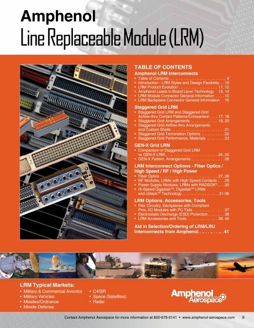
TABLE OF CONTENTS<br />
<strong>Amphenol</strong> <strong>LRM</strong> Interconnects<br />
• Table of Contents . . . .. . .. . .. . .. . .. . .. . .. . .. . .. . .. 9<br />
• Introduction - <strong>LRM</strong> Styles and Design Flexibility ...10<br />
• <strong>LRM</strong> Product Evolution ......................11, 12<br />
• <strong>Amphenol</strong> Leads in Board Level Technology. 13, 14<br />
• <strong>LRM</strong> <strong>Module</strong> Connector General Information .....15<br />
• <strong>LRM</strong> Backplane Connector General Information. 16<br />
Staggered Grid <strong>LRM</strong><br />
• Staggered Grid <strong>LRM</strong> and Staggered Grid<br />
Airflow-thru Contact Patterns/Comparison . .. . 17, 18<br />
• Staggered Grid Arrangements . . . .. . .. . .. . .. . 19, 20<br />
• Staggered Grid Airflow-thru Arrangements<br />
and Custom Shells ..............................21<br />
• Staggered Grid Termination Options . . . .. . .. . .. . .22<br />
• Staggered Grid Performance, Materials ..........23<br />
GEN-X Grid <strong>LRM</strong><br />
• Comparison of Staggered Grid <strong>LRM</strong><br />
vs GEN-X <strong>LRM</strong>..............................24, 25<br />
• GEN-X Pattern, Arrangements. . . .. . .. . .. . .. . .. . .26<br />
<strong>LRM</strong> Interconnect Options - Fiber Optics /<br />
High Speed / RF / High Power<br />
• Fiber Optics .................................27, 28<br />
• RF <strong>Module</strong>s, <strong>LRM</strong>s with High Speed Contacts. . . . 29<br />
• Power Supply <strong>Module</strong>s, <strong>LRM</strong>s with RADSOK ® ....30<br />
• Hi-Speed Gigastak TM , Digastak TM <strong>LRM</strong>s<br />
and cStack TM Technology .....................31-36<br />
<strong>LRM</strong> Options, Accessories, Tools<br />
• Flex Circuitry, Backplanes with Compliant<br />
Pins, I/O <strong>Module</strong>s with PC Tails ..................37<br />
• Electrostatic Discharge (ESD) Protection .........38<br />
• <strong>LRM</strong> Accessories and Tools .................39, 40<br />
Aid in Selection/Ordering of <strong>LRM</strong>/LRU<br />
Interconnects from <strong>Amphenol</strong> . .. . . .. . . .. .41<br />
<strong>LRM</strong> Typical Markets:<br />
• Military & Commercial Avionics<br />
• Military Vehicles<br />
• Missiles/Ordnance<br />
• Missile Defense<br />
• C4ISR<br />
• Space (Satellites)<br />
• Radar<br />
<strong>Amphenol</strong><br />
<strong>Aerospace</strong><br />
Contact <strong>Amphenol</strong> <strong>Aerospace</strong> for more information at 800-678-0141 • www.amphenol-aerospace.com<br />
9
<strong>Amphenol</strong><br />
<strong>Aerospace</strong><br />
<strong>Amphenol</strong> ® <strong>Line</strong> <strong>Replaceable</strong> <strong>Module</strong> (<strong>LRM</strong>)<br />
High Performance Board Level Interconnects<br />
INTRODUCTION - <strong>LRM</strong> STYLES & DESIGN FLEXIBILITY<br />
Introduction/<br />
Pkg. Solutions/<br />
Brush Contact<br />
<strong>LRM</strong> (<strong>Line</strong> <strong>Replaceable</strong> <strong>Module</strong>s)<br />
Staggered/<br />
GEN-X<br />
Hybrids - Fiber Optics/<br />
Hi Speed/RF/Power<br />
Options/<br />
Accessories<br />
Ruggedized<br />
VME64x /<br />
VITA 60, 66<br />
Staggered Grid <strong>LRM</strong><br />
GEN-X Grid <strong>LRM</strong><br />
High contact density in SEM-E<br />
and custom form factors<br />
Higher contact density and<br />
improved electrical performance<br />
<strong>Amphenol</strong> ® <strong>LRM</strong> Surface Mount Connectors meet the<br />
high density needs of today’s integrated electronic<br />
modules.<br />
<strong>Amphenol</strong> goes beyond the usual board level product<br />
offering: and that is what you would expect from a<br />
worldwide interconnect product leader.<br />
MODULAR AVIONICS ARCHITECTURAL<br />
POSSIBILITIES<br />
With its flexibility in design, <strong>Amphenol</strong> <strong>LRM</strong> interconnects are<br />
capable of meeting the wide variety of user requirements for<br />
a board mount connector.<br />
• Thousands of combinations of inserts are possible -<br />
tailored to meet user needs<br />
• <strong>LRM</strong> interconnects can be designed in 1, 2, 3 (and more)<br />
bay configurations with many shell designs available<br />
• <strong>LRM</strong> digital (brush) inserts can be combined with inserts<br />
for power, fiber optics, RF, high speed and high amperage<br />
RADSOK ® contacts<br />
High Density<br />
HSB3 HDB3<br />
Hi Speed<br />
High Speed <strong>LRM</strong><br />
Inserts with 3.125 Gb/s and 6.25<br />
Gb/s data rate capability, with flex<br />
termination. Can be added to<br />
existing <strong>LRM</strong> configurations.<br />
DESIGN FLEXIBILITY<br />
Fiber optic<br />
MT ferrules<br />
Standard brush contacts<br />
in a differential pair insert<br />
Low Mating Force MIL-DTL-55302<br />
Standard<br />
Brush<br />
Hybrids - Signal/Power/<br />
Coax/Fiber Optics<br />
Docking Conn./<br />
Accessories/Install.<br />
<strong>LRM</strong> INTERCONNECTS FEATURE<br />
AMPHENOL’S BRUSH CONTACT TECHNOLOGY<br />
Multiple strands of high tensile strength wire bundled together to<br />
form brush-like contacts. See the Introduction & Brush Contact<br />
Technology section of this catalog for further description.<br />
RADSOK ®<br />
high amperage<br />
contacts<br />
Six bay<br />
connector<br />
shell<br />
Flex termination<br />
Partially populated brush<br />
contact bay to facilitate high<br />
voltage transmission<br />
Rack & Panel<br />
Brush<br />
Ruggedized<br />
LMD/LMS<br />
Rectangular<br />
Interconnects<br />
• With its low mating force, stable electrical performance and<br />
extended service life, the B 3 Brush contact is the standard<br />
contact for the <strong>LRM</strong>.<br />
• Digital (Brush) inserts can be combined with each other or<br />
with inserts for power, RF, fiber optic and high speed<br />
contacts.<br />
High speed<br />
differential pair<br />
brush contacts<br />
Other<br />
Rectangular<br />
Interconnects<br />
NOTE: This catalog section supersedes <strong>Amphenol</strong>’s older individual catalog on <strong>LRM</strong> products, 12-037.<br />
2 inserts with standard<br />
brush contacts<br />
10<br />
Contact <strong>Amphenol</strong> <strong>Aerospace</strong> for more information at 800-678-0141 • www.amphenol-aerospace.com
<strong>Amphenol</strong> ® <strong>Line</strong> <strong>Replaceable</strong> <strong>Module</strong> (<strong>LRM</strong>)<br />
Interconnects<br />
<strong>LRM</strong> PRODUCT EVOLUTION<br />
<strong>Amphenol</strong><br />
<strong>Aerospace</strong><br />
<strong>Amphenol</strong> has been committed to keeping pace with the ever-changing demands of the<br />
rectangular connector marketplace. Starting with the development of the B3 contact, incorporated<br />
into the low mating force PCB connectors, and later with the development of the line<br />
replaceable module (<strong>LRM</strong>), <strong>Amphenol</strong> has led the way in the avionics packaging industry for<br />
high quality rectangular products. This page and the following page give an overview of the<br />
rectangular product evolution.<br />
Low Mating Force Connector with Bristle Brush Contacts*<br />
• Developed in the 1980’s to provide solutions to problems caused by the high<br />
mating and unmating forces of conventional pin and socket contact pairs.<br />
• 4 Body styles: mother board (MB), daughter board (DB), PC connector, input/<br />
output connector<br />
• Molded of thermoplastic material<br />
• 2, 3 and 4 row configurations, 10 to 100 contacts per row in one contact row<br />
increments<br />
• 100 inch center to center contact spacing, square grid<br />
• Qualified to MIL-DTL-55302/166, /167, /168, /170<br />
<strong>Line</strong> <strong>Replaceable</strong> <strong>Module</strong> (<strong>LRM</strong>) Connectors with Chevron Grid**<br />
• Developed to meet the avionics packaging requirements for a surface mount,<br />
high contact density PCB connector in a SEM-E form factor.<br />
• Digital insert pattern grid: 6 rows, 0.075” spacing along rows, 0.075” between<br />
rows with 0.025” offset.<br />
** This is an older design of the <strong>LRM</strong> and is typically not used today.<br />
Staggered and GEN-X designs have replaced the Chevron design<br />
(Consult <strong>Amphenol</strong> for further details)<br />
<strong>LRM</strong> Connectors with Staggered Grid<br />
• Advanced design to provide higher contact density for high speed integrated<br />
circuitry in SEM-E and custom form factors.<br />
• Digital insert pattern grid is in 8 rows: 0.100 inch spacing along the row with<br />
0.050 inch between rows, rows offset 0.050 inch. Typical standard<br />
arrangements would have 80 or 108 or 152 or 180 digital brush contacts.<br />
• Options include various shell designs options to accommodate a wide range<br />
of PC board/heat sink combinations<br />
• Surface mount termination on module connectors, PCB or compliant<br />
termination on backplane connectors<br />
• <strong>Amphenol</strong> ESD protection (in module connector)<br />
- Designed for level 2 (flight line) maintenance<br />
• Provides routing channels for backplane<br />
<strong>Amphenol</strong> Staggered Grid Connectors<br />
are the connector of choice for the F-16<br />
and F-22 Aircraft. The following were the<br />
criteria that determined the selection of<br />
the connector for the F-16, F-22 and F-35<br />
aircraft:<br />
• Reliability: Impervious to fretting<br />
corrosion, Micro-arching<br />
• ESD Protection<br />
* See the Brush Contact Technology section,<br />
and the Low Mating Force MIL-DTL-55302 section of this catalog.<br />
Low Mating Force Connectors - the first<br />
development of rectangulars with Brush<br />
contacts.<br />
Staggered Grid <strong>LRM</strong> was chosen for the F-16 and F-22 Aircraft<br />
<strong>LRM</strong> Chevron Grid (150+180 contact pattern)<br />
(<strong>Amphenol</strong>’s first <strong>LRM</strong> design)<br />
<strong>LRM</strong> Staggered Grid (180 contact pattern)<br />
<strong>Amphenol</strong>’s higher density <strong>LRM</strong> with more<br />
advantages.<br />
<strong>Amphenol</strong> <strong>LRM</strong> Evolution continues on next page.<br />
Introduction/<br />
Pkg. Solutions/<br />
Brush Contact<br />
<strong>LRM</strong> (<strong>Line</strong> <strong>Replaceable</strong> <strong>Module</strong>s)<br />
Staggered/ Hybrids - Fiber Optics/ Options/<br />
GEN-X Hi Speed/RF/Power Accessories<br />
Ruggedized<br />
VME 64x/<br />
VITA 60, 66<br />
High Density<br />
HDB3 HSB3<br />
Hi Speed<br />
Standard<br />
Brush<br />
Hybrids - Signal/Power/ Docking Conn./<br />
Coax/Fiber Optics Accessories/Install.<br />
Low Mating Force MIL-DTL-55302<br />
Rack & Panel<br />
Brush<br />
Ruggedized<br />
LMD/LMS<br />
Rectangular<br />
Interconnects<br />
Other<br />
Rectangular<br />
Interconnects<br />
Contact <strong>Amphenol</strong> <strong>Aerospace</strong> for more information at 800-678-0141 • www.amphenol-aerospace.com<br />
11
<strong>Amphenol</strong><br />
<strong>Aerospace</strong><br />
<strong>Amphenol</strong> ® <strong>Line</strong> <strong>Replaceable</strong> <strong>Module</strong> (<strong>LRM</strong>)<br />
Interconnects<br />
<strong>LRM</strong> PRODUCT EVOLUTION, CONTINUED<br />
Introduction/<br />
Pkg. Solutions/<br />
Brush Contact<br />
<strong>LRM</strong> (<strong>Line</strong> <strong>Replaceable</strong> <strong>Module</strong>s)<br />
Staggered/<br />
GEN-X<br />
Hybrids - Fiber Optics/<br />
Hi Speed/RF/Power<br />
Options/<br />
Accessories<br />
Ruggedized<br />
VME64x /<br />
VITA 60, 66<br />
High Density<br />
HSB3 HDB3<br />
Hi Speed<br />
Low Mating Force MIL-DTL-55302<br />
Standard<br />
Brush<br />
Hybrids - Signal/Power/<br />
Coax/Fiber Optics<br />
Docking Conn./<br />
Accessories/Install.<br />
Rack & Panel<br />
Brush<br />
Ruggedized<br />
LMD/LMS<br />
Rectangular<br />
Interconnects<br />
Certainly not standing still, and continuing to expand product offering,<br />
<strong>Amphenol</strong> now provides <strong>LRM</strong>s with higher contact densities, special purpose<br />
configurations and high speed inserts.<br />
<strong>LRM</strong> Connectors with GEN-X Grid<br />
• Higher contact density and improved electrical performance<br />
• All the features of staggered <strong>LRM</strong>, including ESD protection (module connector)<br />
• Available in SEM-E and custom form factors<br />
• 236 contact pattern grid in 8 rows: 0.075 inch spacing along the row with 0.060<br />
inch between rows, rows offset 0.0375 inch<br />
<strong>LRM</strong> Staggered Grid Airflow-thru Connectors<br />
• <strong>LRM</strong> Staggered Airflow-thru inserts are available for wider board packages up to<br />
0.425 in. These accommodate standard B 3 tails in staggered pattern, but with<br />
increased spacing in the center, to accommodate airflow through heatsinks<br />
<strong>LRM</strong> Connectors with Fiber Optics<br />
• Custom combinations of digital contacts and fiber optic termini were offered as<br />
the product line further developed in the ‘90’s.<br />
• Configurations included:<br />
• MIL-T-29504/4, /5, /14 & /15 termini<br />
• MT ferrule arrangements (2-24 fiber lines per ferrule)<br />
<strong>LRM</strong> Connectors to Accommodate RF Contacts<br />
• <strong>LRM</strong> inserts are available with RF contacts:<br />
• Size 16 M39029/79 & /80 shielded contacts<br />
• Size 12 coax for DC-2 GHz; size 8 coax for DC-32 GHz<br />
• SMPM coax contacts*<br />
• <strong>LRM</strong> Power Supply <strong>Module</strong>s<br />
• Custom designs of <strong>LRM</strong>s have been developed with<br />
270VDC sections which are capable of providing<br />
corona-free operation at 100,000 feet. They utilize size 22D contacts<br />
and are available in both crimp and compliant pin terminations.<br />
<strong>LRM</strong> with High Amperage RADSOK ® Contacts<br />
• The RADSOK ® contact technology enables high current flow with<br />
minimal voltage loss and low insertion force<br />
Board Level Interconnects of 2010 and Beyond -<br />
More and more the customer has demanded<br />
a high level of flexibility, with designs that<br />
incorporate higher speeds and special<br />
features going beyond the standard <strong>LRM</strong>.<br />
Configurations such as:<br />
• High speed GigaStak ® <strong>LRM</strong> connectors<br />
- capable of data rates up to 6.25 Gb/s,<br />
and DigiStak ® <strong>LRM</strong> connectors capable<br />
of data rates up to 3.125 Gb/s<br />
• High speed shielded contacts -<br />
coax, triax, twinax, differential twinax, and<br />
quadrax contacts available in inserts of the <strong>LRM</strong><br />
• Combinations of power contacts, standard brush,<br />
high power, differential pair brush, and fiber optic termini<br />
<strong>LRM</strong> with Fiber Optic MT Ferrules<br />
High Speed GigaStak ® , capable of<br />
data rates of 6.250 Gbps<br />
• Incorporation of Flex Circuits for more versatility of PC board terminations<br />
• Custom shells with multiple bay configurations, special keying<br />
components or special guide/ground pins<br />
• Compliant pin contacts for press-fit termination to circuit boards.<br />
<strong>LRM</strong> GEN-X Grid (236 contact pattern)<br />
Even higher densities with all the benefits of<br />
the Staggered Grid.<br />
<strong>LRM</strong> Staggered Grid Airflow-thru<br />
<strong>LRM</strong> with RF Contacts<br />
<strong>LRM</strong> backplane (left) and module connector (right)<br />
incorporating high amperage RADSOK ® contacts<br />
(crimp style shown).<br />
<strong>LRM</strong> special 6 bay design with RADSOK ® contacts,<br />
standard brush contacts, and flex circuitry termination<br />
to module circuit card assemblies<br />
Other<br />
Rectangular<br />
Interconnects<br />
<strong>Amphenol</strong> Backplane Capabilities<br />
<strong>Amphenol</strong> backplanes incorporate a wide range of our interconnects.<br />
See Other Rectangular Interconnects Section of this catalog, page 117, for more<br />
information on <strong>Amphenol</strong> backplanes.<br />
* See Other Rectangular Interconnects<br />
Section, page 126 for more<br />
information on SMPM contacts.<br />
12<br />
Contact <strong>Amphenol</strong> <strong>Aerospace</strong> for more information at 800-678-0141 • www.amphenol-aerospace.com
<strong>Amphenol</strong> Leads in Board Level<br />
Product Technology<br />
<strong>LRM</strong> DESIGN ENGINEERING<br />
<strong>Amphenol</strong><br />
<strong>Aerospace</strong><br />
We take pride that <strong>Amphenol</strong> <strong>Aerospace</strong> is the undisputed<br />
leader in interconnect systems for aerospace/harsh<br />
environment applications. Such applications require a high<br />
degree of engineering sophistication and precision manufacturing<br />
capability that only a company that has been in<br />
the interconnection product design and manufacturing<br />
business for over 50 years can offer.<br />
We have earned the reputation as the leader in the military<br />
electrical connection arena especially for military cylindrical<br />
connectors, and are fast becoming the leader for rectangular<br />
and surface mount interconnects.<br />
Our <strong>LRM</strong> and VME64x* products are used on major<br />
programs that include the following and more:<br />
• F-35 • JTRS • EA18G<br />
• F-16 • M1A2 Tank • EA6B<br />
• F-15 • F-117 • MEADS<br />
• F/A-22 • AH-64 APACHE • G/ATOR<br />
• F/A-18 • ASRAAM • EQ-36<br />
• B2 • B52<br />
Expert design and applications engineering provides solid<br />
modeling and full Pro-Engineer ® capabilities to develop<br />
new interconnection designs and perform structural<br />
analysis. Marketing product managers team with skilled<br />
engineers and production specialists in a customer-driven<br />
approach to produce the end result: defect-free parts, cost<br />
effectiveness, shorter lead and delivery times, and satisfied<br />
customers.<br />
The photo top right shows the CST Microwave Studio ®<br />
signal integrity modeling and simulation software at<br />
<strong>Amphenol</strong>. This state-of-the-art technology allows characterization<br />
of current connector designs and rapidly aids in<br />
the development of new high speed signal designs. It<br />
consists of a 3D, full-wave electromagnetic field solver for<br />
simulating electrical performance, producing SPICE<br />
models and eye diagrams.<br />
<strong>Amphenol</strong>’s capability for testing of it’s wide range of<br />
cylindrical and rectangular connector products also<br />
includes vibration<br />
and shock testing,<br />
humidity, engagement/separation<br />
force evaluation,<br />
durability testing, as<br />
well as salt spray/<br />
fog, corona, ESD,<br />
optical performance<br />
testing and altitude<br />
simulation.<br />
Close-up photo showing vertical machining<br />
of heatsink housings done at <strong>Amphenol</strong>.<br />
* VME64x products are covered on page 43.<br />
Engineers working at the signal integrity modeling and simulation<br />
software suite at <strong>Amphenol</strong> <strong>Aerospace</strong> Operations. (See page 28<br />
for more information on <strong>Amphenol</strong>’s testing of Hi-Speed <strong>LRM</strong><br />
connectors).<br />
Above and below are production areas for <strong>LRM</strong> interconnects and<br />
heatsinks. Note the orange balls on the machines - these are used<br />
as a quick checking device for processes.<br />
Introduction/<br />
Pkg. Solutions/<br />
Brush Contact<br />
<strong>LRM</strong> (<strong>Line</strong> <strong>Replaceable</strong> <strong>Module</strong>s)<br />
Staggered/ Hybrids - Fiber Optics/ Options/<br />
GEN-X Hi Speed/RF/Power Accessories<br />
Ruggedized<br />
VME 64x/<br />
VITA 60, 66<br />
High Density<br />
HDB3 HSB3<br />
Hi Speed<br />
Standard<br />
Brush<br />
Hybrids - Signal/Power/ Docking Conn./<br />
Coax/Fiber Optics Accessories/Install.<br />
Low Mating Force MIL-DTL-55302<br />
Rack & Panel<br />
Brush<br />
Ruggedized<br />
LMD/LMS<br />
Rectangular<br />
Interconnects<br />
Other<br />
Rectangular<br />
Interconnects<br />
Contact <strong>Amphenol</strong> <strong>Aerospace</strong> for more information at 800-678-0141 • www.amphenol-aerospace.com<br />
13
<strong>Amphenol</strong><br />
<strong>Aerospace</strong><br />
<strong>Amphenol</strong> Leads in Board Level<br />
Technology<br />
<strong>LRM</strong> MANUFACTURING EXPERTISE<br />
Introduction/<br />
Pkg. Solutions/<br />
Brush Contact<br />
<strong>LRM</strong> (<strong>Line</strong> <strong>Replaceable</strong> <strong>Module</strong>s)<br />
Staggered/<br />
GEN-X<br />
Hybrids - Fiber Optics/<br />
Hi Speed/RF/Power<br />
Options/<br />
Accessories<br />
Ruggedized<br />
VME64x /<br />
VITA 60, 66<br />
<strong>Amphenol</strong> <strong>Aerospace</strong> is highly integrated to design,<br />
manufacture, assemble and ship an extensive<br />
variety of line replaceable module and backplane<br />
connectors. We also supply a wide range of<br />
heatsink hardware associated with this type of<br />
connector. The photo on right shows several<br />
heatsink forms used in the manufacture of <strong>LRM</strong><br />
interconnects. For more information on heatsinks,<br />
see the Other Board Level and Rectangular<br />
Interconnects Section, pages 112 & 113.<br />
Manufacturing equipment photos shown below<br />
demonstrate <strong>Amphenol</strong>’s high technology capability.<br />
Focus is always on cost effective production and<br />
continuous improvement of processes. Manufacturing<br />
capabilities include state-of-the-art robotically<br />
controlled milling machines and CNC machining, as<br />
well as impact and extruding, plating, screw<br />
machining, and process control.<br />
Variety of heatsinks and connector shells manufactured by <strong>Amphenol</strong>.<br />
Low Mating Force MIL-DTL-55302<br />
Standard<br />
Brush<br />
High Density<br />
HSB3 HDB3<br />
Hi Speed<br />
Hybrids - Signal/Power/<br />
Coax/Fiber Optics<br />
Docking Conn./<br />
Accessories/Install.<br />
Rack & Panel<br />
Brush<br />
Ruggedized<br />
LMD/LMS<br />
Rectangular<br />
Interconnects<br />
Other<br />
Rectangular<br />
Interconnects<br />
CMM measuring is done to check machined parts.<br />
THE ADVANTAGE OF AMPHENOL’S WIDE DIVISIONAL<br />
CAPABILITY<br />
<strong>Amphenol</strong> divisions work together to provide a very broad manufacturing<br />
capability for board level interconnects:<br />
• <strong>Amphenol</strong> <strong>Aerospace</strong> (AAO)* has leading expertise in the<br />
production of line replaceable module inter-connects, VME64x<br />
interconnects and low mating force brush connectors.<br />
• <strong>Amphenol</strong> Backplane Systems (ABS)** has leading expertise in the<br />
manufacture of custom backplane assemblies - high density,<br />
ruggedized, board to backplane interconnects.<br />
• <strong>Amphenol</strong> Printed Circuits (APC)*** has leading expertise in the<br />
manufacture of flex circuitry products used in connector-to-board<br />
attachment.<br />
These companies of <strong>Amphenol</strong> Corporation combine to provide<br />
design, applications engineering, fabrication, value-added assembly<br />
and testing to meet customer requirements as well as to develop<br />
products for emerging technologies.<br />
* This catalog covers the rectangular interconnect products offered by AAO division. Go online at www.<br />
amphenol-aerospace to see the wide range of cylindrical and other interconnect products offered by<br />
AAO. And see the Other Rectangular Products section at the end of this catalog for other <strong>Amphenol</strong><br />
divisions offerings of rectangular interconnects.<br />
** For more information on backplane assemblies: page 117 and online at www.amphenol-abs.com.<br />
*** For more information on flex circuit products: page 121 and online at www.amphenolapc.com.<br />
<strong>Amphenol</strong>’s high technology computer driven equipment<br />
for manufacturing heatsinks.<br />
Checking for dimensional accuracy of <strong>LRM</strong><br />
parts and heatsinks.<br />
14<br />
Contact <strong>Amphenol</strong> <strong>Aerospace</strong> for more information at 800-678-0141 • www.amphenol-aerospace.com
<strong>LRM</strong> <strong>Module</strong> Connector<br />
General Information<br />
STAGGERED GRID DOUBLE BAY SHOWN<br />
<strong>Amphenol</strong><br />
<strong>Aerospace</strong><br />
The following is the <strong>LRM</strong> <strong>Module</strong> Connector identification<br />
and naming convention. The illustration is a double bay<br />
module with a staggered grid pattern.<br />
Introduction/<br />
Pkg. Solutions/<br />
Brush Contact<br />
POLARIZATION<br />
KEYS (4)<br />
SHELL TYPE 2<br />
(TOP)<br />
SHELL<br />
ATTACHING<br />
SCREWS<br />
INSERT POSITION<br />
“A” BETA END<br />
SPLIT TYPE REF<br />
INSERT POSITION<br />
“B” BETA END<br />
SPLIT TYPE REF<br />
INSERT POSITION<br />
“A” ALPHA END<br />
SPLIT TYPE REF<br />
INSERT POSITION<br />
“B” ALPHA END<br />
SPLIT TYPE REF<br />
SIDE “B”<br />
GUIDE PIN (2)<br />
<strong>LRM</strong> (<strong>Line</strong> <strong>Replaceable</strong> <strong>Module</strong>s)<br />
Staggered/ Hybrids - Fiber Optics/ Options/<br />
GEN-X Hi Speed/RF/Power Accessories<br />
SIDE “A”<br />
SHELL TYPE 1<br />
(BOTTOM)<br />
Ruggedized<br />
VME 64x/<br />
VITA 60, 66<br />
High Density<br />
HDB3 HSB3<br />
Hi Speed<br />
“B” PCB<br />
“A” PCB<br />
SOLDER<br />
PADS FOR<br />
CONTACT TAILS<br />
Standard<br />
Brush<br />
Hybrids - Signal/Power/ Docking Conn./<br />
Coax/Fiber Optics Accessories/Install.<br />
Low Mating Force MIL-DTL-55302<br />
Rack & Panel<br />
Brush<br />
Ruggedized<br />
TOP HALF OF<br />
CUSTOMER DESIGNED COVER<br />
REFERENCE<br />
BOTTOM<br />
COVER<br />
REFERENCE<br />
LMD/LMS<br />
Rectangular<br />
Interconnects<br />
HEATSINK<br />
Other<br />
Rectangular<br />
Interconnects<br />
Contact <strong>Amphenol</strong> <strong>Aerospace</strong> for more information at 800-678-0141 • www.amphenol-aerospace.com<br />
15
<strong>Amphenol</strong><br />
<strong>Aerospace</strong><br />
<strong>LRM</strong> Backplane Connector<br />
General Information<br />
STAGGERED GRID DOUBLE BAY SHOWN<br />
Introduction/<br />
Pkg. Solutions/<br />
Brush Contact<br />
The following diagram shows an exploded view of an<br />
<strong>LRM</strong> staggered grid backplane connector in a two bay<br />
configuration.<br />
<strong>LRM</strong> (<strong>Line</strong> <strong>Replaceable</strong> <strong>Module</strong>s)<br />
Staggered/<br />
GEN-X<br />
Hybrids - Fiber Optics/<br />
Hi Speed/RF/Power<br />
Options/<br />
Accessories<br />
BACKPLANE CONNECTOR SHELL<br />
(TYPICAL CONTAINMENT OF 2 BAY INSERT<br />
ASSEMBLY SHOWN)<br />
Ruggedized<br />
VME64x /<br />
VITA 60, 66<br />
BRUSH PINS<br />
Low Mating Force MIL-DTL-55302<br />
Other<br />
Rectangular<br />
Interconnects<br />
LMD/LMS<br />
Rectangular<br />
Interconnects<br />
Standard<br />
Brush<br />
Hybrids - Signal/Power/<br />
Coax/Fiber Optics<br />
Docking Conn./<br />
Accessories/Install.<br />
Rack & Panel<br />
Brush<br />
Ruggedized<br />
High Density<br />
HSB3 HDB3<br />
Hi Speed<br />
BACKPLANE PCB<br />
STAGGERED STYLE<br />
INSERT ASSEMBLY<br />
(360 BRUSH CONTACTS<br />
SHOWN)<br />
16<br />
Contact <strong>Amphenol</strong> <strong>Aerospace</strong> for more information at 800-678-0141 • www.amphenol-aerospace.com
Staggered Grid <strong>LRM</strong> &<br />
Staggered Grid Airflow-thru<br />
CONTACT PATTERNS<br />
<strong>Amphenol</strong><br />
<strong>Aerospace</strong><br />
STAGGERED GRID DESCRIPTION<br />
The <strong>LRM</strong> standard staggered grid pattern<br />
employs surface mount leads on .025 inch<br />
centerlines (pitch). Insert patterns of digital<br />
brush contacts are in 80, 108, 152 and 180<br />
contact counts. See typical arrangement<br />
drawings on pages 19 and 20.<br />
Connector<br />
Centerline<br />
STAGGERED<br />
.050<br />
TYP<br />
.075<br />
TYP<br />
.050<br />
TYP<br />
.150 TYP<br />
( 3X .050 )<br />
.150 TYP<br />
( 3X .050 )<br />
Introduction/<br />
Pkg. Solutions/<br />
Brush Contact<br />
<strong>LRM</strong> (<strong>Line</strong> <strong>Replaceable</strong> <strong>Module</strong>s)<br />
Staggered/ Hybrids - Fiber Optics/ Options/<br />
GEN-X Hi Speed/RF/Power Accessories<br />
All dimensions in inches.<br />
.050 TYP<br />
.100 TYP<br />
Ruggedized<br />
VME 64x/<br />
VITA 60, 66<br />
High Density<br />
HDB3 HSB3<br />
Hi Speed<br />
Two bay, 360 contact, module connector with standard staggered grid pattern<br />
STAGGERED AIRFLOW-THRU GRID<br />
DESCRIPTION<br />
The staggered grid airflow-thru inserts were<br />
designed to accommodate wider board<br />
packaging and airflow-thru heatsinks. Insert<br />
patterns of digital brush contacts are same<br />
as the staggered grid pattern (80, 108, 152<br />
and 180 contact counts). See typical<br />
arrangement drawings on page 21.<br />
Connector<br />
Centerline<br />
STAGGERED AIRFLOW-THRU<br />
.050<br />
TYP<br />
.250<br />
TYP<br />
.150 TYP<br />
( 3X .050 )<br />
Standard<br />
Brush<br />
Hybrids - Signal/Power/ Docking Conn./<br />
Coax/Fiber Optics Accessories/Install.<br />
Low Mating Force MIL-DTL-55302<br />
Rack & Panel<br />
Brush<br />
Ruggedized<br />
.050<br />
TYP<br />
.150 TYP<br />
( 3X .050 )<br />
LMD/LMS<br />
Rectangular<br />
Interconnects<br />
Staggered grid airflow-thru backplane insert.<br />
All dimensions in inches.<br />
.100 TYP<br />
.050 TYP<br />
Other<br />
Rectangular<br />
Interconnects<br />
Contact <strong>Amphenol</strong> <strong>Aerospace</strong> for more information at 800-678-0141 • www.amphenol-aerospace.com<br />
17
<strong>Amphenol</strong><br />
<strong>Aerospace</strong><br />
Staggered Grid <strong>LRM</strong> &<br />
Staggered Grid Airflow-thru<br />
CONTACT PATTERNS/COMPARISON<br />
Introduction/<br />
Pkg. Solutions/<br />
Brush Contact<br />
<strong>LRM</strong> (<strong>Line</strong> <strong>Replaceable</strong> <strong>Module</strong>s)<br />
Staggered/<br />
GEN-X<br />
Hybrids - Fiber Optics/<br />
Hi Speed/RF/Power<br />
Options/<br />
Accessories<br />
Staggered Grid (Standard)<br />
Staggered Grid for Standard<br />
Board Packages<br />
.075<br />
.050<br />
.100<br />
.0875<br />
.1875<br />
.1375<br />
.0375<br />
.375<br />
Staggered Grid Airflow-Thru<br />
Staggered Grid Air-flow for Wider<br />
Board Packages<br />
.100<br />
.050<br />
.175<br />
.250<br />
.125<br />
.225<br />
.275<br />
.550<br />
Other<br />
Rectangular<br />
Interconnects<br />
LMD/LMS<br />
Rectangular<br />
Interconnects<br />
High Density<br />
HSB3 HDB3<br />
Hi Speed<br />
Rack & Panel<br />
Brush<br />
Ruggedized<br />
Low Mating Force MIL-DTL-55302<br />
Docking Conn./<br />
Accessories/Install.<br />
Hybrids - Signal/Power/<br />
Coax/Fiber Optics<br />
Standard<br />
Brush<br />
Ruggedized<br />
VME64x /<br />
VITA 60, 66<br />
1 2<br />
1 2<br />
18<br />
Contact <strong>Amphenol</strong> <strong>Aerospace</strong> for more information at 800-678-0141 • www.amphenol-aerospace.com
Staggered Grid <strong>LRM</strong><br />
TYPICAL ARRANGEMENTS<br />
<strong>Amphenol</strong><br />
<strong>Aerospace</strong><br />
Example of a backplane connector in a 2 bay arrangement with inserts<br />
of staggered brush contacts and coax (size 12) contacts.<br />
80 brush contacts<br />
108 brush contacts<br />
152 brush contacts<br />
180 brush contacts<br />
108 brush contacts plus 6 sz. 12 power or<br />
coax contacts<br />
108 brush contacts plus 8 coax contacts<br />
Staggered Grid <strong>LRM</strong> interconnects can be one,<br />
two or three bay configurations, and special<br />
additional bay arrangements. The typical arrangements<br />
shown here are depicted in one bay<br />
drawings. <strong>Amphenol</strong>’s design flexibility also allow<br />
for combinations of contact types. These arrangements<br />
represent the versatility that can be arrived<br />
at by arranging digital (brush) inserts with inserts<br />
for power, RF, fiber optic and high speed contacts<br />
in various combinations within a typical bay.<br />
Consult <strong>Amphenol</strong> <strong>Aerospace</strong> for assistance in<br />
designing the <strong>LRM</strong> that best meets your specific<br />
application needs. See page 41 for an aid in<br />
selection and ordering.<br />
152 brush contacts plus 2 sz. 12 power or coax contacts<br />
152 brush contacts plus 4 sz. 16 power or<br />
coax contacts<br />
152 brush contacts plus 2 sz. 12 power or coax contacts<br />
108 brush contacts plus 270 VDC power input<br />
Introduction/<br />
Pkg. Solutions/<br />
Brush Contact<br />
<strong>LRM</strong> (<strong>Line</strong> <strong>Replaceable</strong> <strong>Module</strong>s)<br />
Staggered/ Hybrids - Fiber Optics/ Options/<br />
GEN-X Hi Speed/RF/Power Accessories<br />
Ruggedized<br />
VME 64x/<br />
VITA 60, 66<br />
High Density<br />
HDB3 HSB3<br />
Hi Speed<br />
Standard<br />
Brush<br />
Hybrids - Signal/Power/ Docking Conn./<br />
Coax/Fiber Optics Accessories/Install.<br />
Low Mating Force MIL-DTL-55302<br />
80 brush contacts plus 10 coax contacts<br />
80 brush contacts plus 270 VDC power input<br />
Rack & Panel<br />
Brush<br />
Ruggedized<br />
80 brush contacts plus 12 sz. 12 power or coax contacts<br />
22 sz. 12 power contacts<br />
LMD/LMS<br />
Rectangular<br />
Interconnects<br />
Other<br />
Rectangular<br />
Interconnects<br />
Contact <strong>Amphenol</strong> <strong>Aerospace</strong> for more information at 800-678-0141 • www.amphenol-aerospace.com<br />
19
<strong>Amphenol</strong><br />
<strong>Aerospace</strong><br />
Staggered Grid <strong>LRM</strong><br />
TYPICAL ARRANGEMENTS<br />
Introduction/<br />
Pkg. Solutions/<br />
Brush Contact<br />
144 brush contacts plus 4 fiber optic termini<br />
<strong>LRM</strong> (<strong>Line</strong> <strong>Replaceable</strong> <strong>Module</strong>s)<br />
Staggered/<br />
GEN-X<br />
Hybrids - Fiber Optics/<br />
Hi Speed/RF/Power<br />
Options/<br />
Accessories<br />
108 brush contacts plus 4 coax contacts<br />
and 4 fiber optic termini<br />
80 brush contacts plus 6 coax contacts<br />
Example of a 3 bay module connector with an insert for MT fiber optic<br />
ferrules and inserts for brush LVDs and digital contacts.<br />
Example of a 2 bay staggered grid module connector.<br />
Ruggedized<br />
VME64x /<br />
VITA 60, 66<br />
High Density<br />
HSB3 HDB3<br />
Hi Speed<br />
108 brush contacts plus an insert for 2 fiber optic<br />
MT ferrules*<br />
Low Mating Force MIL-DTL-55302<br />
Standard<br />
Brush<br />
Hybrids - Signal/Power/<br />
Coax/Fiber Optics<br />
Docking Conn./<br />
Accessories/Install.<br />
6 cavities for fiber optic MT ferrules*<br />
8 brush LVDS differential pairs plus an insert for<br />
2 fiber optic MT ferrules*<br />
fiber optic<br />
MT ferrules<br />
(8) grounded contacts<br />
(8) differential<br />
pairs<br />
Example of a staggered grid module and backplane with 108 brush contacts<br />
and an insert for 7 size 20 crimp contacts for high voltage applications.<br />
Rack & Panel<br />
Brush<br />
Ruggedized<br />
LMD/LMS<br />
Rectangular<br />
Interconnects<br />
16 LVD pairs<br />
(16) grounded contacts<br />
(16) differential<br />
pairs<br />
Other<br />
Rectangular<br />
Interconnects<br />
* MT ferrules are not supplied by <strong>Amphenol</strong> <strong>Aerospace</strong>.<br />
see page 28 for more information on <strong>LRM</strong>s with MT<br />
ferrules.<br />
20<br />
Contact <strong>Amphenol</strong> <strong>Aerospace</strong> for more information at 800-678-0141 • www.amphenol-aerospace.com
Staggered Grid Airflow-thru <strong>LRM</strong><br />
ARRANGEMENTS, CUSTOM SHELLS<br />
<strong>Amphenol</strong><br />
<strong>Aerospace</strong><br />
The typical Airflow-thru arrangements are with brush contacts. The<br />
arrangements shown at left for staggered grid Airflow-thru are<br />
typical of what has been developed for customer requirements.<br />
80 brush contacts<br />
(airflow-thru)<br />
108 brush contacts<br />
(airflow-thru)<br />
Introduction/<br />
Pkg. Solutions/<br />
Brush Contact<br />
Staggered Grid Airflow-thru<br />
pattern - in a module on right,<br />
and in a backplane on left.<br />
Note the increased spacing in<br />
the center. This is designed<br />
for wider board packages, and<br />
accommodates airflow-thru<br />
heatsinks. (See illustration on<br />
page 18).<br />
<strong>LRM</strong>s with airflow-thru inserts can be custom designed in<br />
combination with power contacts, such as the example below.<br />
152 brush contacts (airflow-thru)<br />
180 brush contacts (airflow-thru)<br />
<strong>LRM</strong> (<strong>Line</strong> <strong>Replaceable</strong> <strong>Module</strong>s)<br />
Staggered/ Hybrids - Fiber Optics/ Options/<br />
GEN-X Hi Speed/RF/Power Accessories<br />
Ruggedized<br />
VME 64x/<br />
VITA 60, 66<br />
<strong>Module</strong> and backplane connectors with staggered airflow-thru inserts. Shown are<br />
216 brush contacts and inserts for size 12 RADSOK ® crimp contacts.<br />
<strong>Amphenol</strong> designs and builds custom shell<br />
configurations such as the module face plate<br />
and its mating backplane connector.<br />
This custom Airflow-thru module<br />
contains RADSOK ® high<br />
amperage socket contacts in<br />
sizes 8 and 12.<br />
See more description of<br />
RADSOK ® contacts, page 124.<br />
Underside of Backplane, showing<br />
size 8 & 12 RADSOK ® contacts<br />
with compliant termination.<br />
Backplane connector<br />
<strong>Module</strong> connector<br />
Closeup of<br />
insert with<br />
compliant<br />
pin termination<br />
power contacts.<br />
Center inserts contain 108<br />
brush contacts, staggered grid<br />
High Density<br />
HDB3 HSB3<br />
Hi Speed<br />
Standard<br />
Brush<br />
Hybrids - Signal/Power/ Docking Conn./<br />
Coax/Fiber Optics Accessories/Install.<br />
Low Mating Force MIL-DTL-55302<br />
Rack & Panel<br />
Brush<br />
Ruggedized<br />
LMD/LMS<br />
Rectangular<br />
Interconnects<br />
Other<br />
Rectangular<br />
Interconnects<br />
Contact <strong>Amphenol</strong> <strong>Aerospace</strong> for more information at 800-678-0141 • www.amphenol-aerospace.com<br />
21
<strong>Amphenol</strong><br />
<strong>Aerospace</strong><br />
Staggered Grid <strong>LRM</strong><br />
TERMINATION OPTIONS<br />
Introduction/<br />
Pkg. Solutions/<br />
Brush Contact<br />
<strong>LRM</strong> (<strong>Line</strong> <strong>Replaceable</strong> <strong>Module</strong>s)<br />
Staggered/<br />
GEN-X<br />
Hybrids - Fiber Optics/<br />
Hi Speed/RF/Power<br />
Options/<br />
Accessories<br />
Ruggedized<br />
VME64x /<br />
VITA 60, 66<br />
The following is a guide to the part number suffixes to be used when ordering <strong>LRM</strong> Connectors. Due to the complexity<br />
and number of variations within the part numbering, it is necessary to consult <strong>Amphenol</strong> <strong>Aerospace</strong> for assistance<br />
when building these part numbers. See page 41 for an aid in selection and ordering, and call <strong>Amphenol</strong> at 607-563-<br />
5011 for technical support.<br />
MODULE<br />
HEATSINK<br />
THICKNESS<br />
BOARD PACKAGE<br />
THICKNESS<br />
An example of a typical <strong>Amphenol</strong> <strong>Module</strong><br />
An example of a typical <strong>Amphenol</strong> Backplane<br />
part number is: 10-507XXX-X( )( ) part number is:<br />
10-507XXX-X( )( )<br />
10-507 .....Designates <strong>Amphenol</strong><br />
<strong>LRM</strong> Connectors<br />
BACKPLANE<br />
TERMINATION<br />
STICKOUT<br />
10-507 .....Designates <strong>Amphenol</strong><br />
<strong>LRM</strong> Connectors<br />
High Density<br />
HSB3 HDB3<br />
Hi Speed<br />
Low Mating Force MIL-DTL-55302<br />
Standard<br />
Brush<br />
Hybrids - Signal/Power/<br />
Coax/Fiber Optics<br />
Docking Conn./<br />
Accessories/Install.<br />
Rack & Panel<br />
Brush<br />
Ruggedized<br />
LMD/LMS<br />
Rectangular<br />
Interconnects<br />
XXX-X ......<strong>Module</strong> Insert Arrangement<br />
Number - To be assigned by <strong>Amphenol</strong>.<br />
( ) ............Heatsink Thickness Suffix for <strong>Module</strong>s<br />
Suffix Description<br />
1 .125 ±.005<br />
2 .100 ±.005<br />
3 .075 ±.005<br />
4 .062 ±.005<br />
( ) ............Board Package Thickness Suffix for<br />
<strong>Module</strong>s<br />
Description<br />
Suffix Standard<br />
Staggered<br />
1 Surface Mount /<br />
.090 – .130 Package<br />
2 Surface Mount /<br />
.130 – .190 Package<br />
3 Surface Mount /<br />
.190 – .250 Package<br />
4 Surface Mount /<br />
.060 – .100 Package<br />
5 Surface Mount /<br />
.100 – .160 Package<br />
6 Surface Mount /<br />
.160 – .220 Package<br />
* .175 is added for increased center spacing in the<br />
airflow-thru staggered style<br />
Description<br />
Airflow-thru<br />
Staggered*<br />
Surface Mount /<br />
.265 – .305 Package<br />
Surface Mount /<br />
.305 – .365 Package<br />
Surface Mount /<br />
.365 – .425 Package<br />
Surface Mount /<br />
.235 – .275 Package<br />
Surface Mount /<br />
.275 – .335 Package<br />
Surface Mount /<br />
.335 – .395 Package<br />
XXX-X ......Backplane Insert Arrangement<br />
Number - To be assigned by <strong>Amphenol</strong>.<br />
( ) ............Termination Style Suffix for Backplanes<br />
Suffix Description<br />
1 .021 ±.002 Dia. PCB Tail<br />
2 .016 ±.002 Dia. PCB Tail<br />
5 Compliant<br />
( ) ............Termination Stickout Suffix for<br />
Backplanes<br />
Suffix<br />
Description<br />
1 .150 ±.020 (PCB)<br />
2 .200 ±.020 (PCB)<br />
3 .250 ±.020 (PCB)<br />
4 .300 ±.020 (PCB)<br />
5 .350 ±.020 (PCB)<br />
6 .400 ±.020 (PCB)<br />
7 .185 ±.020 (PCB)<br />
8 .450 ±.020 (PCB)<br />
9 .500 ±.020 (PCB)<br />
C .157 ±.020 (Compliant, No Wrap)<br />
D .217 ±.020 (Compliant, 1 Wrap)<br />
E .317 ±.020 (Compliant, 2 Wrap)<br />
F .417 ±.020 (Compliant, 3 Wrap)<br />
Other<br />
Rectangular<br />
Interconnects<br />
22<br />
Contact <strong>Amphenol</strong> <strong>Aerospace</strong> for more information at 800-678-0141 • www.amphenol-aerospace.com
Staggered Grid <strong>LRM</strong><br />
TYPICAL PERFORMANCE, MATERIALS LIST<br />
<strong>Amphenol</strong><br />
<strong>Aerospace</strong><br />
Table 1 below identifies the typical electrical, mechanical and environmental performance of an <strong>Amphenol</strong> 2 bay <strong>LRM</strong><br />
connector assembly with 360 brush contacts in staggered grid. This data was program specific and does not reflect actual<br />
performance limitations. Table II below provides a materials list for the components of staggered grid <strong>LRM</strong> connectors.<br />
Part<br />
Brush wires<br />
TABLE I: PERFORMANCE<br />
ELECTRICAL PERFORMANCE<br />
Electrical Parameters<br />
Performance<br />
Current carrying capability<br />
10°C temperature rise at 2A and 30°C rise at 3A<br />
Contact resistance<br />
30 milliohms max. per contact, 25 milliohms max. average<br />
Dielectric withstanding voltage at sea level<br />
100 VRMS, 60 Hz<br />
Dielectric withstanding voltage at altitude<br />
100 VRMS, 60 Hz at 70,000 ft.<br />
Insulation Resistance<br />
1000 megohm minimum at 100V d.c.<br />
Electrostatic Discharge Protection (module only)<br />
± 25,000 minimum air and direct discharge (see pg. XX for details)<br />
MECHANICAL PERFORMANCE<br />
Mechanical Parameters<br />
Performance<br />
Contact retention (solder type backplane assembly)<br />
Maximum displacement of 0.010” at 1 pound load<br />
Mating and unmating forces<br />
Maximum 40.0 pounds mating and unmating<br />
Vibration (Sinusoidal, 20g peak max.) No electrical discontinuity >1 µS<br />
Vibration (Random, 11.6g RMS max.) No electrical discontinuity >1 µS<br />
Shock (50g max. shock pulse) No electrical discontinuity >1 µS<br />
Solderability<br />
Minimum 95% solder coverage<br />
Resistance to soldering heat<br />
260°C dip for 10 seconds<br />
ENVIRONMENTAL PERFORMANCE<br />
Environmental Parameters<br />
Performance<br />
Temperature life<br />
250 hours at 125°C maximum<br />
Connector durability<br />
500 cycles mating and unmating<br />
Salt fog exposure<br />
48 hours maximum direct exposure (5% NaCl)<br />
Thermal shock<br />
500 cycles at +125°C / –65°C<br />
Humidity exposure 240 hours at 90 - 98%<br />
Contamination exposure Sand and dust per MIL-STD-202 Method 110<br />
Resistance to solvents<br />
Boiling Trichloroethylene fumes and solution<br />
<strong>Module</strong> contacts<br />
Backplane contacts<br />
(Compliant<br />
termination)<br />
Backplane contacts<br />
(PCB termination)<br />
Insulators<br />
Organizer<br />
TABLE II: MATERIALS LIST<br />
ENVIRONMENTAL PERFORMANCE<br />
Material / Finish Description<br />
Beryllium copper per ASTM B197; finish is gold per ASTM B488 over nickel per AMS-QQ-N-290. (The exposed ends of the<br />
brush wires need not be plated).<br />
Beryllium copper per ASTM B534 C17500, or C17510 except temper HTC; finish on contact body is matte tin-lead per<br />
ASTM B579; finish on termination end is 60/40 or 63/37 tin-lead dip per J-STD-004, -005 and -006.<br />
Contact barrel: brass per ASTM B4531/B453M-01 similar to UNS C33500; finish is tin-lead per SAE-AMS-P-81728<br />
(min. 15% ±5% lead) over nickel. Contact tail: beryllium copper per ASTM B-534 alloy 17510 HT; finish is gold per ASTM B-488<br />
over nickel per AMS-QQ-N-290. Contact sleeve: stainless steel per AMS 5514; finish is black oxide per MIL-DTL-13924 and<br />
conformally coated per MIL-I-46058.<br />
Contact body: brass similar to UNS C33500; finish is gold over nickel; termination end is 60/40 or 63/37 tin lead dip.<br />
Contact sleeve: stainless steel per AMS 5514; finish is black oxide per MIL-DTL-13924 and conformally coated per MIL-I-46058.<br />
Polyphenylene Sulfide or Liquid Crystal Polymer per MIL-M-24519<br />
Polyphenylene Sulfide or Liquid Crystal Polymer per MIL-M-24519<br />
Shells Aluminum alloy 6061-T6 per AMS 4150; finish is electroless nickel per SAE AMS 2404.<br />
ESD shields<br />
Polarization keys<br />
Guide pins<br />
Aluminum alloy 6061-T6 per AMS 4150; finish is hardcoat anodize per MIL-A-8625 with epoxy final coat. Ground tabs are<br />
chromate treated (irridite).<br />
Stainless steel per AMS 5640; finish is black oxide per MIL-DTL-13924. Key retaining ring is Polyamide (nylon 12) with<br />
50% glass filled fibers.<br />
Beryllium copper alloy per ASTM B196, finish is gold per ASTM B 488 over nickel per AMS-QQ-N-290.<br />
Introduction/<br />
Pkg. Solutions/<br />
Brush Contact<br />
<strong>LRM</strong> (<strong>Line</strong> <strong>Replaceable</strong> <strong>Module</strong>s)<br />
Staggered/ Hybrids - Fiber Optics/ Options/<br />
GEN-X Hi Speed/RF/Power Accessories<br />
Ruggedized<br />
VME 64x/<br />
VITA 60, 66<br />
High Density<br />
HDB3 HSB3<br />
Hi Speed<br />
Standard<br />
Brush<br />
Hybrids - Signal/Power/ Docking Conn./<br />
Coax/Fiber Optics Accessories/Install.<br />
Low Mating Force MIL-DTL-55302<br />
Rack & Panel<br />
Brush<br />
Ruggedized<br />
LMD/LMS<br />
Rectangular<br />
Interconnects<br />
Other<br />
Rectangular<br />
Interconnects<br />
Contact <strong>Amphenol</strong> <strong>Aerospace</strong> for more information at 800-678-0141 • www.amphenol-aerospace.com<br />
23
<strong>Amphenol</strong><br />
<strong>Aerospace</strong><br />
Staggered Grid <strong>LRM</strong> vs GEN-X Grid<br />
GEN-X PROVIDES HIGHER CONTACT DENSITY<br />
Introduction/<br />
Pkg. Solutions/<br />
Brush Contact<br />
Staggered Grid Contact Density<br />
GEN-X Contact Density<br />
<strong>LRM</strong> (<strong>Line</strong> <strong>Replaceable</strong> <strong>Module</strong>s)<br />
Staggered/<br />
GEN-X<br />
Hybrids - Fiber Optics/<br />
Hi Speed/RF/Power<br />
Options/<br />
Accessories<br />
.075<br />
.050<br />
.100<br />
.0875<br />
.1875<br />
.1375<br />
.0375<br />
.375<br />
.070<br />
.0375<br />
.075<br />
.095<br />
.215<br />
.035 .155<br />
.430<br />
Ruggedized<br />
VME64x /<br />
VITA 60, 66<br />
Staggered Grid <strong>Module</strong> Termination<br />
GEN-X <strong>Module</strong> Termination<br />
High Density<br />
HSB3 HDB3<br />
Hi Speed<br />
Two Surface Mount<br />
Planes<br />
Four Surface Mount<br />
Planes<br />
HEATSINK<br />
Low Mating Force MIL-DTL-55302<br />
Standard<br />
Brush<br />
Hybrids - Signal/Power/<br />
Coax/Fiber Optics<br />
Docking Conn./<br />
Accessories/Install.<br />
1 2<br />
1 2 3 4<br />
MAIN RIGID<br />
PCB<br />
FLEX<br />
CIRCUITRY<br />
INTERFACE<br />
RIGID PCB<br />
Other<br />
Rectangular<br />
Interconnects<br />
LMD/LMS<br />
Rectangular<br />
Interconnects<br />
Rack & Panel<br />
Brush<br />
Ruggedized<br />
24<br />
Contact <strong>Amphenol</strong> <strong>Aerospace</strong> for more information at 800-678-0141 • www.amphenol-aerospace.com
Staggered Grid <strong>LRM</strong> vs GEN-X Grid<br />
GEN-X PROVIDES HIGHER CONTACT DENSITY<br />
<strong>Amphenol</strong><br />
<strong>Aerospace</strong><br />
Staggered Grid Tail to Tail Placement<br />
Staggered Grid <strong>LRM</strong> has<br />
0.025 tail to tail centerline<br />
spacing<br />
GEN-X Tail to Tail Placement<br />
GEN-X Grid <strong>LRM</strong> has<br />
0.0375 tail to tail centerline<br />
spacing<br />
Introduction/<br />
Pkg. Solutions/<br />
Brush Contact<br />
<strong>LRM</strong> (<strong>Line</strong> <strong>Replaceable</strong> <strong>Module</strong>s)<br />
Staggered/ Hybrids - Fiber Optics/ Options/<br />
GEN-X Hi Speed/RF/Power Accessories<br />
Ruggedized<br />
VME 64x/<br />
VITA 60, 66<br />
High Density<br />
HDB3 HSB3<br />
Hi Speed<br />
GEN-X is Designed to Terminate to Rigid-Flex PCB Attachment<br />
INTERFACE RIGID PCB<br />
MODULE<br />
INSERT ASSEMBLY<br />
Standard<br />
Brush<br />
Hybrids - Signal/Power/ Docking Conn./<br />
Coax/Fiber Optics Accessories/Install.<br />
Low Mating Force MIL-DTL-55302<br />
MAIN RIGID PCB<br />
HEATSINK<br />
FLEX<br />
CIRCUITRY<br />
Rack & Panel<br />
Brush<br />
Ruggedized<br />
LMD/LMS<br />
Rectangular<br />
Interconnects<br />
Other<br />
Rectangular<br />
Interconnects<br />
Contact <strong>Amphenol</strong> <strong>Aerospace</strong> for more information at 800-678-0141 • www.amphenol-aerospace.com<br />
25
<strong>Amphenol</strong><br />
<strong>Aerospace</strong><br />
GEN-X Grid <strong>LRM</strong><br />
CONTACT PATTERN & ARRANGEMENTS<br />
Introduction/<br />
Pkg. Solutions/<br />
Brush Contact<br />
<strong>LRM</strong> (<strong>Line</strong> <strong>Replaceable</strong> <strong>Module</strong>s)<br />
Staggered/<br />
GEN-X<br />
Hybrids - Fiber Optics/<br />
Hi Speed/RF/Power<br />
Options/<br />
Accessories<br />
The <strong>LRM</strong> GEN-X pattern employs<br />
surface mount leads on a .0375<br />
inch center line (module connector),<br />
yet provides higher contact density<br />
than the Staggered grid pattern.<br />
GEN-X provides all the same features<br />
as the staggered grid <strong>LRM</strong>:<br />
• GEN-X digital (brush) inserts are<br />
available in 118 and 236 pin contact<br />
counts.<br />
• Digital contacts can also be combined with<br />
inserts for fiber optics, RF, poser and high<br />
speed contacts.<br />
• Various combinations of inserts can be<br />
provided in 1, 2 or 3 bay shell configurations.<br />
• Typical insert arrangements shown here are<br />
depicted in one bay drawing.<br />
Example of a 3 bay GEN-X backplane connector.<br />
GEN-X<br />
.060<br />
Spacing<br />
Ruggedized<br />
VME64x /<br />
VITA 60, 66<br />
High Density<br />
HSB3 HDB3<br />
Hi Speed<br />
Consult <strong>Amphenol</strong> <strong>Aerospace</strong> for assistance<br />
in designing the <strong>LRM</strong> that best meets your<br />
specific application needs. See page 41 for<br />
an aid in selection and ordering of <strong>LRM</strong> and<br />
LRU interconnects.<br />
.430<br />
.035<br />
.070<br />
Low Mating Force MIL-DTL-55302<br />
Standard<br />
Brush<br />
Hybrids - Signal/Power/<br />
Coax/Fiber Optics<br />
Docking Conn./<br />
Accessories/Install.<br />
Rack & Panel<br />
Brush<br />
Ruggedized<br />
LMD/LMS<br />
Rectangular<br />
Interconnects<br />
118 brush contacts<br />
236 brush contacts<br />
140 brush contacts plus an insert for 2<br />
fiber optic MT ferrules*<br />
212 brush contacts plus 2 sz. 16 power or<br />
coax contacts<br />
All dimensions in inches.<br />
.075<br />
170 brush contacts plus 6 sz. 16 power or<br />
coax contacts<br />
170 brush contacts plus 4 fiber optic termini<br />
and 2 sz. 16 contacts<br />
.0375 Offset<br />
Example of a 2 bay GEN-X module connector.<br />
Other<br />
Rectangular<br />
Interconnects<br />
* MT ferrules are not supplied by <strong>Amphenol</strong> <strong>Aerospace</strong>.<br />
see page 28 for more information on <strong>LRM</strong>s with MT ferrules.<br />
26<br />
Contact <strong>Amphenol</strong> <strong>Aerospace</strong> for more information at 800-678-0141 • www.amphenol-aerospace.com
<strong>LRM</strong> Interconnect Options<br />
<strong>LRM</strong>S WITH FIBER OPTIC TERMINI<br />
<strong>Amphenol</strong><br />
<strong>Aerospace</strong><br />
High speed fiber optic transmission is available within <strong>LRM</strong> connectors for use in<br />
advanced avionics systems. Optical performance of fiber optic termini within in<br />
<strong>LRM</strong> connectors are the same as termini used in circular connectors.*<br />
Insertion losses range from .3dB to<br />
<strong>Amphenol</strong><br />
<strong>Aerospace</strong><br />
<strong>LRM</strong> Interconnect Options<br />
<strong>LRM</strong>S WITH INSERTS FOR MT FERRULE FIBER OPTICS<br />
Introduction/<br />
Pkg. Solutions/<br />
Brush Contact<br />
<strong>LRM</strong> (<strong>Line</strong> <strong>Replaceable</strong> <strong>Module</strong>s)<br />
Staggered/<br />
GEN-X<br />
Hybrids - Fiber Optics/<br />
Hi Speed/RF/Power<br />
Options/<br />
Accessories<br />
Ruggedized<br />
VME64x /<br />
VITA 60, 66<br />
High Density<br />
HSB3 HDB3<br />
Hi Speed<br />
Low Mating Force MIL-DTL-55302<br />
Standard<br />
Brush<br />
Hybrids - Signal/Power/<br />
Coax/Fiber Optics<br />
Docking Conn./<br />
Accessories/Install.<br />
Through <strong>Amphenol</strong>’s <strong>LRM</strong> design flexibility,<br />
inserts are available to house high speed MT ferrules which<br />
can have 12 fiber lines per ferrule or 24 fiber lines per ferrule.<br />
MT ferrules are not supplied by <strong>Amphenol</strong>; they must be<br />
purchased separately.<br />
Termini for rectangular <strong>LRM</strong> connectors<br />
are determined by insert and shell style of<br />
the connector.<br />
Staggered Grid Patterns with MT Ferrule<br />
Fiber Optics<br />
(These drawings are also shown with other staggered grid<br />
patterns on pages 19 and 20).<br />
Insert with cavities<br />
for 6 fiber optic MT<br />
ferrules<br />
Insert with 8 brush<br />
differential pairs plus<br />
an insert for 2 fiber<br />
optic MT ferrules<br />
Insert for 108 brush<br />
contacts plus an insert<br />
for 2 fiber optic MT<br />
ferrules<br />
GEN-X Patterns with MT Ferrule Fiber Optics<br />
(These drawings are also shown with other GEN-X<br />
patterns on page 26).<br />
140 brush contacts<br />
plus an insert for<br />
2 fiber optic MT<br />
ferrules<br />
Example of an <strong>LRM</strong> module connector with MT fiber optic inserts in combination<br />
with inserts for brush LVDs and digital contacts.<br />
<strong>LRM</strong> <strong>Module</strong> Insert Assembly<br />
with MT Termini<br />
FRONT<br />
INSERT<br />
MT FERRULE<br />
WITH RIBBON<br />
SPRING<br />
<strong>LRM</strong> Backplane Insert Assembly<br />
with MT Termini<br />
REAR INSERT<br />
PIN CLAMP<br />
STRAIN<br />
RELIEF<br />
Rack & Panel<br />
Brush<br />
Ruggedized<br />
LMD/LMS<br />
Rectangular<br />
Interconnects<br />
Other<br />
Rectangular<br />
Interconnects<br />
<strong>Amphenol</strong> can supply optical backplane assemblies; see more<br />
informationin the Other Board Level and Rectangular Interconnects<br />
Section on page 117.<br />
FRONT<br />
INSERT<br />
MT FERRULE<br />
WITH RIBBON<br />
REAR<br />
INSERT<br />
28<br />
Contact <strong>Amphenol</strong> <strong>Aerospace</strong> for more information at 800-678-0141 • www.amphenol-aerospace.com
<strong>LRM</strong> Interconnect Options<br />
RF MODULES, <strong>LRM</strong>S WITH HIGH SPEED CONTACTS<br />
<strong>Amphenol</strong><br />
<strong>Aerospace</strong><br />
<strong>LRM</strong> inserts have been designed to accommodate the<br />
following RF and high speed coaxial contacts:<br />
• Size 16 M39029/79 & /80 shielded contacts<br />
• Size 12 coax for DC-65 GHz<br />
• Size 8 coax for DC-32 GHz<br />
• SMPM RF contacts*<br />
• Hybrid arrangements with RF or high speed shielded<br />
contacts and brush contact combinations<br />
Staggered Grid Patterns with RF/Coaxial Contacts<br />
(These drawings are also shown with other staggered grid<br />
patterns on pages 19 and 20).<br />
108 brush contacts plus<br />
an insert for 8 SMPM*<br />
style RF contacts<br />
80 brush contacts plus<br />
an insert for 10 SMPM*<br />
style RF contacts<br />
80 brush contacts plus<br />
an insert for 6 RF<br />
contacts<br />
108 brush contacts plus<br />
inserts for 4 shielded<br />
contacts and 4 fiber optic<br />
termini<br />
152 brush contacts plus<br />
an insert for 2 SMPM*<br />
style RF contacts<br />
152 brush contacts plus<br />
an insert for 4 sz. 16<br />
shielded contacts<br />
* See more information on SMPM RF contacts in Other Rectangular<br />
Interconnects Section, page 126. SMPM RF contacts can be supplied by<br />
<strong>Amphenol</strong> SV Microwave. Phone: 561-840-1800<br />
Website: www.svmicrowave.com<br />
<strong>Amphenol</strong> has also developed inserts with brush differential<br />
pair contacts that are 100 ohm matched impedance. These<br />
support data rates with excess of 1.2 Gbps.<br />
RF module and backplane with size 8 coaxial contacts<br />
Staggered grid module with cavities for size 12 coaxial contacts<br />
GEN-X Patterns with RF/Coaxial Contacts<br />
(These drawings are also shown with other GEN-X patterns on<br />
page 26).<br />
212 brush contacts plus<br />
an insert for 2 sz. 16<br />
shielded contacts<br />
170 brush contacts plus<br />
an insert for 6 sz. 16<br />
shielded contacts<br />
Introduction/<br />
Pkg. Solutions/<br />
Brush Contact<br />
<strong>LRM</strong> (<strong>Line</strong> <strong>Replaceable</strong> <strong>Module</strong>s)<br />
Staggered/ Hybrids - Fiber Optics/ Options/<br />
GEN-X Hi Speed/RF/Power Accessories<br />
Ruggedized<br />
VME 64x/<br />
VITA 60, 66<br />
High Density<br />
HDB3 HSB3<br />
Hi Speed<br />
Standard<br />
Brush<br />
Hybrids - Signal/Power/ Docking Conn./<br />
Coax/Fiber Optics Accessories/Install.<br />
Low Mating Force MIL-DTL-55302<br />
Staggered Grid Patterns with LVDS Differential Pairs<br />
(These drawings are also shown with other staggered grid patterns on<br />
page 20).<br />
Rack & Panel<br />
Brush<br />
Ruggedized<br />
8 brush differential pairs plus<br />
an insert for 2 fiber optic MT<br />
ferrules<br />
16 LVDS differential pairs<br />
<strong>Module</strong> and backplane with LVDS differential pair brush<br />
contacts<br />
LMD/LMS<br />
Rectangular<br />
Interconnects<br />
Other<br />
Rectangular<br />
Interconnects<br />
Contact <strong>Amphenol</strong> <strong>Aerospace</strong> for more information at 800-678-0141 • www.amphenol-aerospace.com<br />
29
<strong>Amphenol</strong><br />
<strong>Aerospace</strong><br />
<strong>LRM</strong> Interconnect Options<br />
POWER SUPPLY MODULES, <strong>LRM</strong>S WITH RADSOK ®<br />
Introduction/<br />
Pkg. Solutions/<br />
Brush Contact<br />
<strong>LRM</strong> (<strong>Line</strong> <strong>Replaceable</strong> <strong>Module</strong>s)<br />
Staggered/<br />
GEN-X<br />
Hybrids - Fiber Optics/<br />
Hi Speed/RF/Power<br />
Options/<br />
Accessories<br />
Ruggedized<br />
VME64x /<br />
VITA 60, 66<br />
High Density<br />
HSB3 HDB3<br />
Hi Speed<br />
Low Mating Force MIL-DTL-55302<br />
Standard<br />
Brush<br />
Hybrids - Signal/Power/<br />
Coax/Fiber Optics<br />
Docking Conn./<br />
Accessories/Install.<br />
Rack & Panel<br />
Brush<br />
Ruggedized<br />
Power Supply <strong>Module</strong>s<br />
<strong>Amphenol</strong> has designed several custom 270VDC sections<br />
which are capable of providing corona-free operation at 75,000<br />
ft. They utilize size 22D contacts and are available in both crimp<br />
and compliant pin terminations.<br />
<strong>Amphenol</strong> has developed the patterns shown below that<br />
incorporate 270 VDC power modules.<br />
(These drawings are also shown with other staggered grid patterns on<br />
page 19).<br />
108 brush contacts plus<br />
270 VDC power input<br />
80 brush contacts plus<br />
270 VDC power input<br />
New/Featured Product<br />
<strong>LRM</strong> Connectors with RADSOK ® Contacts<br />
High Amperage RADSOK ® socket contacts have been designed into <strong>LRM</strong><br />
connectors in response to customer needs for passing of larger amounts of<br />
current with lower mating forces which standard contacts will not handle.<br />
The connector design shown at right has 8 groups of 3 bussed RADSOK<br />
3.6mm sockets (24 contacts total). Each group of 3 is expected to handle a<br />
maximum of 140A. Mating pins for the RADSOK ® sockets are press-fit into<br />
aluminum bus bars behind the motherboard connector.<br />
The RADSOK ® socket cylinder within female<br />
contact has several equally spaced longitudinal<br />
beams twisted into a hyperbolic shape. As<br />
the male pin is inserted, axial members in the<br />
female half deflect, imparting high current flow<br />
across the connection with minimal voltage<br />
loss. The hyperbolic, stamped grid configuration<br />
ensures a large, coaxial, face-to-face<br />
surface area engagement.<br />
See more interconnects that<br />
incorporate RADSOK ® contacts in<br />
the Other Board Level and Rectangular<br />
Interconnects Section, pages<br />
124 & 125. Also, for more information<br />
on <strong>Amphenol</strong> RADSOK ®<br />
connectors, see the <strong>Amphenol</strong><br />
Industrial Operations catalog<br />
SL-391 on-line at www.amphenolindustrial.com.<br />
Power supply modules<br />
<strong>LRM</strong> inserts with RADSOK ® high amperage<br />
contacts<br />
RADSOK ® Power<br />
VDC Power<br />
LMD/LMS<br />
Rectangular<br />
Interconnects<br />
Other<br />
Rectangular<br />
Interconnects<br />
<strong>Module</strong> and backplane connector with the staggered<br />
airflow-thru pattern insert of 54 brush contacts, plus<br />
inserts for 270 VDC power, and 12 size 12 RADSOK ®<br />
crimp contacts.<br />
30<br />
Contact <strong>Amphenol</strong> <strong>Aerospace</strong> for more information at 800-678-0141 • www.amphenol-aerospace.com
Hi-Speed <strong>LRM</strong> Connectors<br />
NEW <strong>LRM</strong>S PROVIDE HIGHER SPEED DATA TRANSFERENCE<br />
New/Featured Product<br />
<strong>Amphenol</strong>’s <strong>LRM</strong> connectors meet today’s need for high speed<br />
interconnects for harsh environments. Constantly evolving and<br />
striving to meet the needs of higher data transfer rates within a<br />
board level product, <strong>Amphenol</strong> has developed <strong>LRM</strong>’s to meet this<br />
challenge. These <strong>LRM</strong>s are designed, or can be configured, to<br />
achieve data rates up to 6.25 Gb/s and include all the features of<br />
our rugged and reliable staggered grid <strong>LRM</strong> series:<br />
• Brush contact interface<br />
• ESD protection (Level 2 flight line classification)<br />
• Connector float<br />
• Guide pins and polarization keys<br />
• Metal shells<br />
• Modular design (hybrid configuration available)<br />
• Accepts wide range of board packages<br />
• Accomodations for custom modular offsets<br />
In addition, the new GigaStak TM , GigaStak-LG TM and DigiStak TM<br />
Series incorporate <strong>Amphenol</strong>’s cStack TM solderless termination<br />
technology (see page 35 for details).<br />
Versatility<br />
Unique flex and cStack terminations accommodate a variety of<br />
mounting configurations and a wide range of board packages.<br />
Connectors can terminate in a variety of ways:<br />
• “traditional” 2 board/heatsink package<br />
• to one or both sides of a single board<br />
• as an offset board package<br />
DigiStak module connectors allow mating to existing configurations<br />
of backplane connectors (users can upgrade solder termination<br />
module connectors to the solderless cStack termination).<br />
The Hi-Speed Family of <strong>LRM</strong> Connectors and associated<br />
data rates includes:<br />
• Gigastak TM - 6.25 Gb/s<br />
• Gigastak LG TM - 3.125 Gb/s<br />
• Digistak TM & Digistak-X TM - 3.125 Gb/s<br />
• Standard Staggered Grid - 1.25 Gb/s<br />
Example of a Hi-Speed Hybrid Connector<br />
Hi-Speed Inserts<br />
GigaStak TM<br />
DigiStak TM<br />
<strong>Amphenol</strong><br />
<strong>Aerospace</strong><br />
DigiStak TM<br />
DigiStak TM Inserts<br />
GigaStak<br />
LG TM<br />
GigaStak TM Hi-Speed Inserts (left & right: 60 Brush<br />
differential pairs; middle: 18 Brush differential pairs plus<br />
180 Brush low speed signal contacts)<br />
Hybrid Connector that has GigaStak-LG TM and DigiStak TM<br />
Inserts , shown on Testing Boards<br />
Introduction/<br />
Pkg. Solutions/<br />
Brush Contact<br />
<strong>LRM</strong> (<strong>Line</strong> <strong>Replaceable</strong> <strong>Module</strong>s)<br />
Staggered/ Hybrids - Fiber Optics/ Options/<br />
GEN-X Hi Speed/RF/Power Accessories<br />
Ruggedized<br />
VME 64x/<br />
VITA 60, 66<br />
High Density<br />
HDB3 HSB3<br />
Hi Speed<br />
Standard<br />
Brush<br />
Hybrids - Signal/Power/ Docking Conn./<br />
Coax/Fiber Optics Accessories/Install.<br />
Low Mating Force MIL-DTL-55302<br />
Rack & Panel<br />
Brush<br />
Ruggedized<br />
Insert for RF or<br />
Power contacts<br />
LMD/LMS<br />
Rectangular<br />
Interconnects<br />
GigaStak LG TM<br />
Inserts<br />
DigiStak TM Inserts<br />
Other<br />
Rectangular<br />
Interconnects<br />
Contact <strong>Amphenol</strong> <strong>Aerospace</strong> for more information at 800-678-0141 • www.amphenol-aerospace.com<br />
31
Introduction/<br />
Pkg. Solutions/<br />
Brush Contact<br />
<strong>LRM</strong> (<strong>Line</strong> <strong>Replaceable</strong> <strong>Module</strong>s)<br />
<strong>Amphenol</strong><br />
<strong>Aerospace</strong><br />
Staggered/<br />
GEN-X<br />
Hybrids - Fiber Optics/<br />
Hi Speed/RF/Power<br />
Options/<br />
Accessories<br />
New/Featured Product<br />
Hi-Speed <strong>LRM</strong>s<br />
<strong>Amphenol</strong> has taken the proven and highly reliable<br />
<strong>LRM</strong> Brush connector and incorporated the<br />
cStack TM termination technology - giving the user<br />
hi-speed signal options up to 6.25 Gb/s and a<br />
solderless termination to their CCA.<br />
Through strategic placement of signal and ground contacts,<br />
each insert arrangement is optimized for the perfect balance of<br />
impedance control and cross-talk mitigation for a given data rate.<br />
GigaStak Features:<br />
• Hi-Speed connector designed for both single ended and<br />
differential signals<br />
• Supports data rates of 6.25 Gb/s<br />
• High density providing 30 differential signals per linear inch<br />
• Designed for 100 ohm differential impedance<br />
• Optimized cross-talk<br />
GIGASTAK TM - THE HIGHEST DENSITY HI-SPEED CONNECTOR<br />
Giga<br />
1100110100100<br />
GigaStak TM Backplane Connector<br />
01100110011001101<br />
tak<br />
Built for speed<br />
Ruggedized<br />
VME64x /<br />
VITA 60, 66<br />
GigaStak Patterns<br />
24 Differential Pair*<br />
High Density<br />
HSB3 HDB3<br />
Hi Speed<br />
36 Differential Pair*<br />
48 Differential Pair*<br />
GigaStak TM <strong>Module</strong> Unassembled<br />
Low Mating Force MIL-DTL-55302<br />
Standard<br />
Brush<br />
Hybrids - Signal/Power/<br />
Coax/Fiber Optics<br />
Docking Conn./<br />
Accessories/Install.<br />
* Consult <strong>Amphenol</strong> for availability.<br />
60 Differential Pair<br />
ENLARGED<br />
VIEW<br />
Differential<br />
Pairs<br />
Designated Ground<br />
Contact Rows<br />
Shielding Ground Blades<br />
LMD/LMS<br />
Rectangular<br />
Interconnects<br />
Rack & Panel<br />
Brush<br />
Ruggedized<br />
Other<br />
Rectangular<br />
Interconnects<br />
Validation testing has been performed through<br />
both simulation (CST Microwave Studio) and<br />
actual testing of production connectors. Test<br />
reports, touchstone fles and hardware are<br />
available for review.<br />
ESD Shield<br />
GigaStak 60 Differential Pair Insert with ESD Shield Exploded and<br />
Enlarged Section<br />
32<br />
Contact <strong>Amphenol</strong> <strong>Aerospace</strong> for more information at 800-678-0141 • www.amphenol-aerospace.com
Hi-Speed <strong>LRM</strong>s<br />
GIGASTAK-LG TM<br />
New/Featured Product<br />
The GigaStak-LG TM inserts provide hi-speed data transference,<br />
utilzes cStack solderless termination, and can be<br />
combined with low speed signal contacts, as shown in the<br />
hybrid connector photo below.<br />
GigaStak LG Features:<br />
• Hi-Speed connector designed for differential signals<br />
• Supports data rates of 3.125 Gb/s<br />
• Current Design has 8 differential pairs<br />
• Provides 11 differential signals per linear inch<br />
• Designed for 100 ohm differential impedance<br />
• Optimized cross-talk<br />
GigaStak LG Patterns<br />
23 Differential Pairs<br />
<strong>Amphenol</strong><br />
<strong>Aerospace</strong><br />
GigaStak-LG TM Inserts with 8 Hi-Speed Differential Pairs<br />
Introduction/<br />
Pkg. Solutions/<br />
Brush Contact<br />
<strong>LRM</strong> (<strong>Line</strong> <strong>Replaceable</strong> <strong>Module</strong>s)<br />
Staggered/ Hybrids - Fiber Optics/ Options/<br />
GEN-X Hi Speed/RF/Power Accessories<br />
8 Differential Pairs<br />
and 108 Digital Contacts<br />
Ruggedized<br />
VME 64x/<br />
VITA 60, 66<br />
High Density<br />
HDB3 HSB3<br />
Hi Speed<br />
GigaStak-LG Inserts<br />
with 8 Hi-Speed Differential Pairs Packaged with<br />
Staggered Grid Inserts with Low Speed Signal Contacts<br />
Combined GigaStak-LG and DigiStak Insert<br />
(see next page for DigiStak description)<br />
DigiStak<br />
GigaStak-LG<br />
Standard<br />
Brush<br />
Hybrids - Signal/Power/ Docking Conn./<br />
Coax/Fiber Optics Accessories/Install.<br />
Low Mating Force MIL-DTL-55302<br />
Rack & Panel<br />
Brush<br />
Ruggedized<br />
LMD/LMS<br />
Rectangular<br />
Interconnects<br />
Other<br />
Rectangular<br />
Interconnects<br />
Contact <strong>Amphenol</strong> <strong>Aerospace</strong> for more information at 800-678-0141 • www.amphenol-aerospace.com<br />
33
Introduction/<br />
Pkg. Solutions/<br />
Brush Contact<br />
<strong>LRM</strong> (<strong>Line</strong> <strong>Replaceable</strong> <strong>Module</strong>s)<br />
<strong>Amphenol</strong><br />
<strong>Aerospace</strong><br />
Staggered/<br />
GEN-X<br />
Hybrids - Fiber Optics/<br />
Hi Speed/RF/Power<br />
Options/<br />
Accessories<br />
Ruggedized<br />
VME64x /<br />
VITA 60, 66<br />
New/Featured Product<br />
DigiStak TM Hi-Speed <strong>LRM</strong> Inserts<br />
The DigiStak TM connector provides the<br />
standard staggered grid <strong>LRM</strong> pattern in a<br />
hi-speed connector that utilizes cStack<br />
solderless termination.<br />
DigiStak Features:<br />
• Designed to improve data rates in existing<br />
staggered grid <strong>LRM</strong> inserts<br />
• Supports data rates of 3.125 Gb/s<br />
• Configurable for up to 20 differential pairs per<br />
linear inch<br />
• Designed for 100 ohm differential impedance<br />
• Optimized cross-talk<br />
The DigiStak uses standard staggered grid<br />
insert pattern shown at right. (Pages 19 and<br />
20 show the arrangements of staggered grid<br />
connectors which are also available in the<br />
Digistak connector).<br />
Hi-Speed <strong>LRM</strong>s<br />
DIGISTAK TM AND DIGISTAK-X TM<br />
360 Pin DigiStak <strong>Module</strong> Connector<br />
STAGGERED<br />
(2 sides of same connector)<br />
.050<br />
TYP<br />
.150 TYP<br />
( 3X .050 )<br />
High Density<br />
HSB3 HDB3<br />
Hi Speed<br />
Connector<br />
Centerline<br />
.075<br />
TYP<br />
Low Mating Force MIL-DTL-55302<br />
Standard<br />
Brush<br />
Hybrids - Signal/Power/<br />
Coax/Fiber Optics<br />
Docking Conn./<br />
Accessories/Install.<br />
Rack & Panel<br />
Brush<br />
Ruggedized<br />
LMD/LMS<br />
Rectangular<br />
Interconnects<br />
Other<br />
Rectangular<br />
Interconnects<br />
DigiStak-X TM Hi-Speed <strong>LRM</strong> Inserts<br />
The DigiStak-X TM connector provides the GEN-X<br />
grid <strong>LRM</strong> pattern in a hi-speed connector that<br />
utilizes cStack solderless termination.<br />
DigiStak-X Features:<br />
• Designed to improve data rates in existing<br />
GEN-X <strong>LRM</strong> inserts<br />
• Supports data rates of 3.125 Gb/s<br />
• Configurable for up to 20 differential pairs per<br />
linear inch<br />
• Designed for 100 ohm differential impedance<br />
• Optimized cross-talk<br />
The DigiStak-X uses GEN-X <strong>LRM</strong> grid pattern<br />
shown at right (Page 26 shows the arrangements<br />
of GEN-X grid connectors which are<br />
also available in the Digistak-X connector.<br />
.430<br />
All dimensions in inches.<br />
All dimensions in inches.<br />
GEN-X<br />
.075<br />
.050 TYP<br />
.100 TYP<br />
.0375 Offset<br />
.050<br />
TYP<br />
.060<br />
Spacing<br />
.035<br />
.150 TYP<br />
( 3X .050 )<br />
.070<br />
34<br />
Contact <strong>Amphenol</strong> <strong>Aerospace</strong> for more information at 800-678-0141 • www.amphenol-aerospace.com
Hi-Speed <strong>LRM</strong>s<br />
CSTACK TM TECHNOLOGY<br />
New/Featured Product<br />
Side “A” Bolster<br />
Side “A” Dielectric<br />
Film<br />
Side “A” Interposer<br />
Assembly<br />
Spring-clip ip<br />
Contacts<br />
Side “A” Interposer<br />
Assembly<br />
Side “B” Dielectric<br />
Film<br />
Side “B” Bolster<br />
Threaded Bosses<br />
for Mounting Screws<br />
cStack TM Termination<br />
GigaStak TM , GigaStak-LG TM , DigiStak TM and DigiStak-X TM series<br />
incorporate <strong>Amphenol</strong>’s cStack TM termination which provides the<br />
following features and benefits:<br />
• Flex circuit assemblies that provide high speed, impedance<br />
controlled performance with high signal integrity.<br />
• Flex can be electrically and mechanically customized to fit<br />
system specifications.<br />
• Allows solderless interconnection between flex and board,<br />
eliminating a principal reliability problem with traditional flex<br />
assemblies.<br />
• Standard and customized hardware are available which allow<br />
fast, solderless interconnection with only screw attachment to<br />
boards. Hardware uses captive attachment screws, eliminating<br />
loose component pieces.<br />
Mounting Screws<br />
<strong>Module</strong> Insert Assembly<br />
with PCB Tail Brush<br />
Contacts<br />
Matched Impedance<br />
Multilayer Flex<br />
FR4 Flex<br />
Stiffener/Support<br />
Interposer Gasket<br />
(Optional)<br />
Alignment Pin<br />
(Qty. 2 per Bolster<br />
on Opposite Ends)<br />
<strong>Amphenol</strong><br />
<strong>Aerospace</strong><br />
Anatomy of<br />
cStack TM Technology<br />
Enlarged view of cStack TM<br />
Contact<br />
cStack TM Technology<br />
for Hi-Speed <strong>LRM</strong> Connectors<br />
cStack TM Wafer<br />
(Solderless Surface Mount<br />
Contacts)<br />
Bolster Plate (Stainless<br />
Steel Plate that Compresses<br />
cStack Contacts)<br />
Fasteners (Captive<br />
Hardware for Mounting<br />
cStack to Board)<br />
Flex Circuitry<br />
Introduction/<br />
Pkg. Solutions/<br />
Brush Contact<br />
<strong>LRM</strong> (<strong>Line</strong> <strong>Replaceable</strong> <strong>Module</strong>s)<br />
Staggered/ Hybrids - Fiber Optics/ Options/<br />
GEN-X Hi Speed/RF/Power Accessories<br />
Ruggedized<br />
VME 64x/<br />
VITA 60, 66<br />
High Density<br />
HDB3 HSB3<br />
Hi Speed<br />
Standard<br />
Brush<br />
Hybrids - Signal/Power/ Docking Conn./<br />
Coax/Fiber Optics Accessories/Install.<br />
Low Mating Force MIL-DTL-55302<br />
Rack & Panel<br />
Brush<br />
Ruggedized<br />
See more information on Flex Circuitry in the Other<br />
Rectangular Interconnects Section page 121 of this<br />
catalog.<br />
High Performance<br />
Brush Contacts<br />
LMD/LMS<br />
Rectangular<br />
Interconnects<br />
Other<br />
Rectangular<br />
Interconnects<br />
Contact <strong>Amphenol</strong> <strong>Aerospace</strong> for more information at 800-678-0141 • www.amphenol-aerospace.com<br />
35
<strong>Amphenol</strong><br />
<strong>Aerospace</strong><br />
Hi-Speed <strong>LRM</strong>s<br />
MODELING, SIMULATION, TESTING<br />
Introduction/<br />
Pkg. Solutions/<br />
Brush Contact<br />
<strong>LRM</strong> (<strong>Line</strong> <strong>Replaceable</strong> <strong>Module</strong>s)<br />
Staggered/<br />
GEN-X<br />
Hybrids - Fiber Optics/<br />
Hi Speed/RF/Power<br />
Options/<br />
Accessories<br />
Ruggedized<br />
VME64x /<br />
VITA 60, 66<br />
High Density<br />
HSB3 HDB3<br />
Hi Speed<br />
<strong>Amphenol</strong>’s Capabilities for Modeling and<br />
Testing Hi-Speed Contacts and Connectors<br />
Signal Integrity<br />
• <strong>Amphenol</strong> SI engineers apply their expertise at the<br />
system level and work hard-in-hand with design<br />
engineering<br />
Modeling & Simulation<br />
• <strong>Amphenol</strong> uses powerful modeling, simulation and<br />
analysis tools<br />
• CST Microwave Studio<br />
• Allows characterization of current designs<br />
• Rapidly aids in development of new, high speed<br />
designs<br />
• S-parameter and SPICE analysis<br />
Test Capability<br />
• System level (full thread) and “connector only”<br />
• TDR with iConnect software<br />
• Capability for S-parameter to 15 GHz<br />
• Time domain/eye pattern to 10 Gb/s<br />
• BERT to 6.5 Gb/s<br />
Customer Support<br />
• <strong>Amphenol</strong> SI engineers directly support customers<br />
on their specific applications providing S-parameter<br />
data and Touchstone files<br />
Smith Chart<br />
Low Mating Force MIL-DTL-55302<br />
Standard<br />
Brush<br />
Hybrids - Signal/Power/<br />
Coax/Fiber Optics<br />
Docking Conn./<br />
Accessories/Install.<br />
Hi-Speed Simulation Software used at <strong>Amphenol</strong><br />
<strong>Aerospace</strong>.<br />
3DEM Model/S-Parameter<br />
LMD/LMS<br />
Rectangular<br />
Interconnects<br />
Rack & Panel<br />
Brush<br />
Ruggedized<br />
Other<br />
Rectangular<br />
Interconnects<br />
Test bench for <strong>LRM</strong> connectors. Computer screen shows<br />
a pass/fail mask test eye diagram.<br />
Circuit Simulation Schematic<br />
36<br />
Contact <strong>Amphenol</strong> <strong>Aerospace</strong> for more information at 800-678-0141 • www.amphenol-aerospace.com
<strong>LRM</strong> Interconnect Options<br />
FLEX CIRCUITRY, COMPLIANT PINS, PC TAIL CONTACTS<br />
<strong>Amphenol</strong><br />
<strong>Aerospace</strong><br />
Flex Circuitry Used on <strong>LRM</strong> Connectors<br />
Flex termination can be an integral part of the <strong>LRM</strong><br />
connector insert as shown on top right photo or it can be<br />
used to attach the connector to the printed circuit board,<br />
as shown on next photo below.<br />
When used for attachment to PC boards the flex circuitry<br />
is designed to meet specific length, current carrying<br />
capacity and to fit the precise geometric shape of the<br />
connector to board package. <strong>Amphenol</strong> APC (<strong>Amphenol</strong><br />
Printed Circuits) designs and manufactures the flex<br />
circuitry. Sculptured ® Flexible Circuits have built-in<br />
terminations which eliminate the failures associated with<br />
crimped or soldered-on contacts, as well as geometrically<br />
fitting the tight space requirements within a package.<br />
Flex material is strong and rigid, yet highly flexible.<br />
See page 121 in the Other Rectangular Products section<br />
for more information on Flex circuitry.<br />
Compliant Pins<br />
Compliant pin contacts are available for <strong>LRM</strong><br />
backplane connectors. These are a press fit type<br />
contact which provide reliable, reduced cost,<br />
solderless mounting to printed circuit boards.<br />
Connectors are sold completely assembled with<br />
compliant pins and they accommodate boards with<br />
minimum of 0.125 inch thickness and 0.025 ±.002<br />
plated through holes.<br />
<strong>LRM</strong> backplane insert with compliant pins<br />
<strong>LRM</strong> module inserts with flex termination<br />
Flex circuitry used to attach to PC boards - designed to fit specific<br />
board requirements<br />
PC Tail Contacts<br />
<strong>LRM</strong> modules can be designed with PC tail contacts for<br />
solder mounting on printed circuit boards or flex circuits.<br />
These are called I/O (input-output) <strong>LRM</strong> modules and have<br />
staggered grid pattern.<br />
Introduction/<br />
Pkg. Solutions/<br />
Brush Contact<br />
<strong>LRM</strong> (<strong>Line</strong> <strong>Replaceable</strong> <strong>Module</strong>s)<br />
Staggered/ Hybrids - Fiber Optics/ Options/<br />
GEN-X Hi Speed/RF/Power Accessories<br />
Ruggedized<br />
VME 64x/<br />
VITA 60, 66<br />
High Density<br />
HDB3 HSB3<br />
Hi Speed<br />
Standard<br />
Brush<br />
Hybrids - Signal/Power/ Docking Conn./<br />
Coax/Fiber Optics Accessories/Install.<br />
Low Mating Force MIL-DTL-55302<br />
Rack & Panel<br />
Brush<br />
Ruggedized<br />
<strong>LRM</strong> module inserts (showing front and back of inserts)<br />
with PC tails in staggered grid pattern<br />
LMD/LMS<br />
Rectangular<br />
Interconnects<br />
<strong>LRM</strong> backplane insert with compliant pins for power<br />
contact termination<br />
Other<br />
Rectangular<br />
Interconnects<br />
Contact <strong>Amphenol</strong> <strong>Aerospace</strong> for more information at 800-678-0141 • www.amphenol-aerospace.com<br />
37
<strong>Amphenol</strong><br />
<strong>Aerospace</strong><br />
<strong>LRM</strong> Interconnects with ESD Protection<br />
ELECTROSTATIC DISCHARGE (ESD) PROTECTION<br />
Introduction/<br />
Pkg. Solutions/<br />
Brush Contact<br />
<strong>LRM</strong> (<strong>Line</strong> <strong>Replaceable</strong> <strong>Module</strong>s)<br />
Staggered/<br />
GEN-X<br />
Hybrids - Fiber Optics/<br />
Hi Speed/RF/Power<br />
Options/<br />
Accessories<br />
Ruggedized<br />
VME64x /<br />
VITA 60, 66<br />
High Density<br />
HSB3 HDB3<br />
Hi Speed<br />
Low Mating Force MIL-DTL-55302<br />
Standard<br />
Brush<br />
Hybrids - Signal/Power/<br />
Coax/Fiber Optics<br />
Docking Conn./<br />
Accessories/Install.<br />
Rack & Panel<br />
Brush<br />
Ruggedized<br />
LMD/LMS<br />
Rectangular<br />
Interconnects<br />
Other<br />
Rectangular<br />
Interconnects<br />
<strong>Amphenol</strong> has developed cylindrical and rectangular<br />
connectors which protect sensitive components from<br />
Electrostatic Discharge (ESD) without diodes, varistors,<br />
gas tubes, or “experimental” semiconductive<br />
materials.<br />
These connectors utilize the Faraday Cage principal to<br />
shunt electrostatic discharge events to the conductive<br />
enclosure on which the connector is mounted, thus<br />
never allowing the high voltage, high current discharge<br />
event to reside on any contacts.<br />
The ESD protected connectors have the same physical<br />
envelope as their standard counterparts, and do not<br />
require special mounting or terminating techniques. All<br />
of the contacts remain fully functional, and electrical<br />
characteristics such as capacitance are not affected.<br />
• <strong>LRM</strong> Connectors with ESD protection have the<br />
following features and benefits:<br />
• Connector envelope is identical to unprotected<br />
design for most applications<br />
• Exceeds protection requirements of IEC 801-2 and<br />
MIL-STD-1686:<br />
• Ensures that all components within a conductive<br />
enclosure are not subjected to more than 10V<br />
during electrostatic discharges between –26 KV<br />
and +26 KV<br />
• Voltage observed on contacts during ESD events:<br />
<strong>LRM</strong> Accessories and Tools<br />
TEST PROBE KITS<br />
<strong>Amphenol</strong><br />
<strong>Aerospace</strong><br />
Test Probe Kit - For use with <strong>Amphenol</strong> Brush<br />
Contacts in <strong>LRM</strong> Connectors<br />
<strong>Amphenol</strong> supplies a test probe kit especially designed for<br />
probing brush contacts to insure that they are properly<br />
wired within a connector. It consists of a plastic holder,<br />
insert, and two contacts which are usable for either the<br />
backplane or module connector. It is suggested that the<br />
user buy two kits if they are using connectors of two<br />
genders. The kits are not convertible after assembly.<br />
Instructions for use of Backplane Test Probe -<br />
Slide the insert back over the wire, and crimp contact on.<br />
Follow crimping procedure below. Then snap the insert<br />
contact assembly into the holder.<br />
Instructions for use of <strong>Module</strong> Test Probe -<br />
Slide holder over wire, and then crimp contact. Follow<br />
crimping procedure below. Slide the insert on the contact<br />
and seat it against the shoulder. Slide the holder forward<br />
and snap it onto the insert.<br />
Crimping Procedure -<br />
Using accepted industry procedures, strip wire end to be<br />
terminated 1/8 to 5/32 inches. Care should be taken not to<br />
nick wire strands. Assemble the M22520/2-01 crimp tool<br />
and M22520/2-27 positioner and place tool selector in<br />
correct setting for wire size. Selected wire size must not<br />
have an insulation diameter greater than .062 for the<br />
module probe and not greater than .038 for the backplane<br />
probe.<br />
AWG 22 24 26 28<br />
SEL 5 4 3 2<br />
Insert stripped wire end into contact wire well. Strands<br />
should be visible in wire well inspection hole. Bottom<br />
contact and wire assembly in positioner and close handles<br />
of crimp tool to complete crimp. Handles will not open<br />
unless full crimping cycle has been completed.<br />
Part number for ordering test probe kit is 11-10400-23.<br />
ATTENTION:<br />
Probing brush contacts with anything other than a<br />
brush contact may damage or degrade the brush<br />
contact performance.<br />
Test probe kit 11-10400-23 components<br />
Test probe for brush contact in <strong>LRM</strong> backplane<br />
Test probe for brush contact in <strong>LRM</strong> module<br />
Introduction/<br />
Pkg. Solutions/<br />
Brush Contact<br />
<strong>LRM</strong> (<strong>Line</strong> <strong>Replaceable</strong> <strong>Module</strong>s)<br />
Staggered/ Hybrids - Fiber Optics/ Options/<br />
GEN-X Hi Speed/RF/Power Accessories<br />
Ruggedized<br />
VME 64x/<br />
VITA 60, 66<br />
High Density<br />
HDB3 HSB3<br />
Hi Speed<br />
Standard<br />
Brush<br />
Hybrids - Signal/Power/ Docking Conn./<br />
Coax/Fiber Optics Accessories/Install.<br />
Low Mating Force MIL-DTL-55302<br />
Rack & Panel<br />
Brush<br />
Ruggedized<br />
LMD/LMS<br />
Rectangular<br />
Interconnects<br />
Other<br />
Rectangular<br />
Interconnects<br />
Contact <strong>Amphenol</strong> <strong>Aerospace</strong> for more information at 800-678-0141 • www.amphenol-aerospace.com<br />
39
<strong>Amphenol</strong><br />
<strong>Aerospace</strong><br />
<strong>LRM</strong> Accessories and Tools, cont.<br />
REMOVAL, REPLACEMENT & INSERTION TOOLS<br />
Introduction/<br />
Pkg. Solutions/<br />
Brush Contact<br />
<strong>LRM</strong> (<strong>Line</strong> <strong>Replaceable</strong> <strong>Module</strong>s)<br />
Staggered/<br />
GEN-X<br />
Hybrids - Fiber Optics/<br />
Hi Speed/RF/Power<br />
Options/<br />
Accessories<br />
Ruggedized<br />
VME64x /<br />
VITA 60, 66<br />
High Density<br />
HSB3 HDB3<br />
Hi Speed<br />
Low Mating Force MIL-DTL-55302<br />
Standard<br />
Brush<br />
Hybrids - Signal/Power/<br />
Coax/Fiber Optics<br />
Docking Conn./<br />
Accessories/Install.<br />
Brush Contact Removal, Replacement and Insertion<br />
for Backplane Staggered Grid Connectors<br />
Contacts with solder tails within backplane <strong>LRM</strong> connectors with staggered<br />
grid are not removable or replaceable. User must replace the insert<br />
assembly.<br />
Compliant tail type contacts within backplane <strong>LRM</strong> connectors with<br />
staggered grid are removable and replaceable.<br />
Instructions for removal of compliant contacts: From the back of PC<br />
board side, push contact out through the front of the connector assembly<br />
with contact removal tool #10-507941-1.<br />
Instruction for replacement/insertion of compliant contacts: Using tweezers<br />
or fingers, carefully place the replacement contact, tail first, into the<br />
appropriate contact cavity in the front of the connector. Tweezer tip must<br />
not enter sleeve. Push contact into the cavity with a flat edged rod of<br />
suitable diameter to cover entire contact sleeve circumference until contact<br />
sleeve is flush with adjacent contacts. Do not push against wires or bend<br />
sleeve.<br />
270 VDC Power <strong>Module</strong> Removal, Replacement and Insertion<br />
for Backplane Staggered Grid Connectors<br />
270 VDC power modules can be removed and replaced within the power<br />
insert of an <strong>LRM</strong> connector.<br />
Instructions: Using removal tool #10507924-1 with plunger retracted,<br />
push tool down over the power module from the mating end until retention<br />
tines are released. Use plunger end of tool to push power module out<br />
of the rear the connector.<br />
The power module may be re-installed by hand by pushing it from the rear<br />
of the connector. Push it forward until the retention clips snap into the<br />
power insert cavity of the shell.<br />
The size 22D power contacts within the<br />
power modules are installed and removed<br />
with tool M81969/14-01.<br />
Removal tool 10-507941-1 for removing<br />
compliant contacts from <strong>LRM</strong> backplanes<br />
Removal tool 10-507924-1 (plunger retracted)<br />
for removing 270 VDC power modules from <strong>LRM</strong><br />
backplanes<br />
LMD/LMS<br />
Rectangular<br />
Interconnects<br />
Other<br />
Rectangular<br />
Interconnects<br />
Rack & Panel<br />
Brush<br />
Ruggedized<br />
For <strong>Module</strong> Staggered Grid Connectors:<br />
Contacts within module <strong>LRM</strong> connectors with<br />
staggered grid are not removable or replaceable.<br />
User must replace the insert assembly.<br />
Exploded view - tool 10-507924-1 has removed<br />
power module from backplane. (size 22D<br />
contacts shown removed)<br />
40<br />
Contact <strong>Amphenol</strong> <strong>Aerospace</strong> for more information at 800-678-0141 • www.amphenol-aerospace.com
Aid in Selection and Ordering of <strong>LRM</strong> and LRU<br />
Interconnects from <strong>Amphenol</strong><br />
A FORM THAT CAN BE COPIED AND FAXED TO AMPHENOL<br />
<strong>Amphenol</strong><br />
<strong>Aerospace</strong><br />
The following are questions to be considered when inquiring about <strong>Amphenol</strong> <strong>LRM</strong>/LRU Interconnects. The answers to<br />
these questions will help the <strong>Amphenol</strong> marketing and engineering team to determine the best board level interconnect to<br />
meet your particular needs.<br />
You can copy this page and write your comments on it, and then fax it back to <strong>Amphenol</strong> <strong>Aerospace</strong>, Sidney, NY. Include<br />
your name and company information at the bottom. Fax number: 607-563-5351, Attn: <strong>LRM</strong> product marketing. Or call<br />
<strong>Amphenol</strong> at 607-563-5011 and ask for technical information on <strong>LRM</strong> products.<br />
Footprint Required:<br />
Staggered, GEN-X, NAFI, UHD, Chevron, VME or other:______________________________________________<br />
_______________________________________________________________________________________<br />
Contacts Required:<br />
Digital:__________________________________________________________________________________<br />
Fiber Optic:______________________________________________________________________________<br />
Power:__________________________________________________________________________________<br />
RF:____________________________________________________________________________________<br />
LVDS:__________________________________________________________________________________<br />
<strong>Module</strong> Requirements:<br />
Heatsink Thickness:__________________________________________________________________________<br />
Total Board Package Thickness:_____________________________________________________________<br />
Pitch (module to module):___________________________________________________________________<br />
Straddle Mount, Clamshell or Right Angle:______________________________________________________<br />
Cover Attachment:________________________________________________________________________<br />
Keying:_________________________________________________________________________________<br />
Backplane Requirements:<br />
Termination Style:_________________________________________________________________________<br />
Termination Stickout (Compliant or Solder):_____________________________________________________<br />
Shell Grounding:__________________________________________________________________________<br />
Function Requirements:<br />
Operating Voltage:______________________________<br />
Operating Temperature:______________________<br />
Current Rating:_____________________________<br />
Ambient Temperature:_______________________<br />
Mating Cycles:_____________________________<br />
ESD: Yes or No_____________________________<br />
Float: Yes or No____________________________<br />
Humidity Conditions:_________________________<br />
Function Requirements:<br />
Level of Corrosion Resistance:_________________<br />
Vibration Requirements:______________________<br />
Shock Requirements:________________________<br />
EMI/EMP:_________________________________<br />
Altitude:___________________________________<br />
Durability:_________________________________<br />
Salt Fog:__________________________________<br />
Introduction/<br />
Pkg. Solutions/<br />
Brush Contact<br />
<strong>LRM</strong> (<strong>Line</strong> <strong>Replaceable</strong> <strong>Module</strong>s)<br />
Staggered/ Hybrids - Fiber Optics/ Options/<br />
GEN-X Hi Speed/RF/Power Accessories<br />
Ruggedized<br />
VME 64x/<br />
VITA 60, 66<br />
High Density<br />
HDB3 HSB3<br />
Hi Speed<br />
Standard<br />
Brush<br />
Hybrids - Signal/Power/ Docking Conn./<br />
Coax/Fiber Optics Accessories/Install.<br />
Low Mating Force MIL-DTL-55302<br />
Please fill out information below. Thank you for writing clearly. Fax to 607-563-5351, attention: <strong>LRM</strong> product marketing.<br />
First Name Last Name Phone Number Date<br />
Title Dept./Mail Stop Fax Number<br />
Company Name<br />
Address<br />
City State Zip Code Email Address<br />
Rack & Panel<br />
Brush<br />
Ruggedized<br />
LMD/LMS<br />
Rectangular<br />
Interconnects<br />
Other<br />
Rectangular<br />
Interconnects<br />
Contact <strong>Amphenol</strong> <strong>Aerospace</strong> for more information at 800-678-0141 • www.amphenol-aerospace.com<br />
41


