Repair & Maintenance Repair & Maintenance - Esab
Repair & Maintenance Repair & Maintenance - Esab
Repair & Maintenance Repair & Maintenance - Esab

Create successful ePaper yourself
Turn your PDF publications into a flip-book with our unique Google optimized e-Paper software.
A WELDING REVIEW PUBLISHED BY ESAB VOL. 56 NO.1 2001<br />
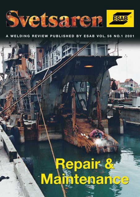
<strong>Repair</strong> &<br />
<strong>Maintenance</strong>
A welding review published by ESAB AB, Sweden No. 1, 2001<br />
Articles in Svetsaren may be reproduced without permission but with<br />
an acknowledgement to ESAB.<br />
Publisher<br />
Bertil Pekkari<br />
Editor<br />
Lennart Lundberg<br />
Editorial committee<br />
Klas Weman, Lars-Göran Eriksson, Johnny Sundin, Johan Elvander, Sten Wallin,<br />
Bob Bitzky, Stan Ferree, Ben Altemühl, Manfred Funccius, Dave Meyer<br />
Address<br />
ESAB AB, Box 8004, SE-402 77 Göteborg, Sweden<br />
Internet address<br />
http://www.esab.com<br />
E-mail: info@esab.se<br />
Printed in Sweden by Geson Skandiatryckeriet, Kungsbacka<br />
<strong>Repair</strong> & <strong>Maintenance</strong>.<br />
Contents Vol. 56 No. 1 2001<br />
3<br />
The repair of aluminium structures<br />
Some of the more common<br />
considerations associated with<br />
the repair of aluminium alloys.<br />
17<br />
Submerged-arc strip cladding of<br />
continuous casting rollers using OK<br />
Band 11.82 and OK Flux 10.07<br />
Surface welding of continuous casting<br />
rollers with submerged arc welding is<br />
preferred because of its higher deposition<br />
rate compared to MAG welding.<br />
6<br />
Advanced production technology leads<br />
to time savings of 25 %<br />
Large pistons for diesel engines are<br />
refurbished by welding rather than<br />
putting a totally new piston into service.<br />
20<br />
ESAB delivers engineered automatic<br />
welding station to Ghana in Africa for<br />
build-up welding of worn railway wheels<br />
Re-building of worn parts of wheel surfaces<br />
by welding is an effective method.<br />
8<br />
Corrosion- and wear-resistant 17%<br />
Cr strip weld overlays<br />
The strip weld-overlay technique used for<br />
renovating of parts in the machinery<br />
manufacturing industry increases productivity<br />
and reduces the likelihood of defects.<br />
22<br />
Cobalarc: The future of manual hardfacing<br />
Electrodes mainly used for hardfacing in<br />
applications where the prime factor of wear<br />
is abrasion.<br />
11<br />
ESAB: your digital partner for welding<br />
and cutting<br />
A guide to the 21 ESAB websites<br />
25<br />
<strong>Repair</strong> welding of blades for rubber<br />
mixing<br />
Re-building of the mixing equipment<br />
used for manufacturing tyres for vehicles.<br />
13<br />
Stubends & Spatter<br />
Short news<br />
2 • Svetsaren nr 1 • 2001
The repair of aluminium<br />
structures<br />
by Tony Anderson, Technical Services Manager AlcoTec Corporation, USA<br />
Without a doubt, aluminum is being increasingly used within the welding<br />
fabrication industry. We are seeing a major increase in usage within the<br />
automotive industry, where the use of aluminum continues to develop. Also<br />
within other industries such as furniture, recreation and sporting equipment,<br />
shipbuilding, transportation and containers, military and aerospace we see<br />
continued developments with aluminum, often as a replacement for steel.<br />
As more components are produced from aluminum, the<br />
need for reliable repair work on aluminum weldments<br />
is also increasing. <strong>Repair</strong> work to aluminum structures<br />
is conducted extremely successfully on a regular basis,<br />
such items as truck body’s and boat hulls are repaired<br />
after damage from collision or after wear and tear<br />
during severe service conditions. This article shall<br />
examine some of the more common considerations<br />
associated with the repair of aluminum alloys in an<br />
attempt to help prevent problems associated with<br />
repair work and also to help ensure consistently<br />
successful repairs.<br />
Identification of alloy type<br />
Probably the most important consideration<br />
encountered during the repair operation is the<br />
identification of the aluminum base alloy type. If the<br />
base material type of the component requiring the<br />
repair is not available through a reliable source, it can<br />
be difficult to select a suitable welding procedure.<br />
There are some guides as to the most probable type of<br />
aluminum used in different applications, such as, most<br />
extruded aluminum is typically 6xxx series (AL-Mg-Si).<br />
Air-conditioning systems and heat exchangers,<br />
within the automotive industry, are typically made from<br />
3003, 5052, plate and 6061 tubing. Car wheels are often<br />
made from 5454, which because of its controlled<br />
magnesium (less than 3% Mg), is suitable for<br />
temperature applications. Ship hulls are often<br />
manufactured from 5083 (5%Mg), which is recognized<br />
as a marine material. Unfortunately, if the base<br />
material type is not known, or unavailable, there is only<br />
one reliable way of establishing the exact type of<br />
aluminum alloy, and that is through chemical analysis.<br />
A small sample of the base material must be sent to a<br />
reliable aluminum testing laboratory, and a chemical<br />
analysis must be performed. Generally, the chemistry<br />
can then be evaluated and a determination as to the<br />
The most important consideration before repair welding is<br />
the identifcation of aluminum base alloy type.<br />
most suitable filler alloy and welding procedure can be<br />
made. It is very important to be aware that incorrect<br />
assumptions as to the chemistry of an aluminum alloy<br />
can result in very serious effects on the welding results.<br />
There are 7 major types of aluminum alloys which<br />
have a wide range of mechanical properties and,<br />
consequently, a wide range of performance and<br />
applications. Some have very good weldability, and<br />
others are considered to have extremely poor<br />
weldability, and are unsuitable, if welded, for structural<br />
applications. Some can be welded with one type of<br />
filler alloy, and others will produce unacceptable,<br />
Svetsaren nr 1 • 2001 • 3
Special care should be taken<br />
when welding high<br />
performance components<br />
such as car rims.<br />
extremely poor mechanical properties if welded with<br />
that same filler alloy. Filler alloy and base alloy<br />
chemistry mixture is one of the main considerations<br />
relating to welded joint suitability, crack sensitivity, and<br />
joint performance. Consequently, without knowing the<br />
base material type, you are unable to assess the correct<br />
filler in order to prevent an unsuitable filler alloy, base<br />
alloy, mixture.<br />
I must definitely recommend that, if an aluminum<br />
component is to be repair welded, and after this, used<br />
for any structural application, particularly, if a weld<br />
failure, can in any way damage property and/or create<br />
injury, do not weld it without understanding its alloy<br />
type, and being satisfied that the correct welding<br />
procedure is to be followed.<br />
The repair of some high performance<br />
aluminum alloys<br />
Another problem associated with the repair of a small<br />
group of aluminum structures is the temptation to<br />
repair high performance, typically high replacement<br />
price components, made from exotic aluminum alloys.<br />
These materials are often found on aircraft, hand<br />
gliders, sporting equipment and other types of highperformance,<br />
safety-critical equipment and are not<br />
usually welded on the original component. There are a<br />
small number of high- performance aluminum alloys<br />
which are generally recognized as being unweldable. It<br />
can be very dangerous to perform welding on these<br />
components and then return them to service. Probably<br />
the two most commonly found aluminum alloys within<br />
this category are 2024, which is an aluminum, copper,<br />
magnesium alloy and 7075, an aluminum, zinc, copper,<br />
magnesium alloy. Both these materials can become<br />
susceptible to stress corrosion cracking after welding.<br />
This phenomenon (stress corrosion cracking)is<br />
particularly dangerous because it is generally a type of<br />
delayed failure, not detectable immediately after<br />
welding, and usually develops at a later date when the<br />
Some automotive components in aluminum that have been<br />
repaired by welding.<br />
component is in service. The completed weld joint can<br />
appear to be of excellent quality immediately after<br />
welding. X-rays and ultrasonic inspection shortly after<br />
welding will typically find no indication of a welding<br />
problem. However, changes which occur within the<br />
base material adjacent to the weld during the welding<br />
process, can produce a metallurgical condition within<br />
these materials which can result in intergranular micro<br />
cracking, which may be susceptible to propagation and<br />
eventual failure of the welded component.<br />
The probability of failure can be high, and the time<br />
to failure is generally unpredictable and dependent on<br />
variables such as tensile stress applied to the joint,<br />
environmental conditions, and the period of time which<br />
the component is subjected to these variables.<br />
It is strongly recommended that great care be taken<br />
when considering the repair of components made from<br />
these materials. Again, it must be stressed that if there<br />
is any possibility of a weld failure becoming the cause<br />
of damage or injury to person or property, do not<br />
perform repair work by welding on these alloys and<br />
then return them to service.<br />
4 • Svetsaren nr 1 • 2001
Base material strength reduction after repair welding:<br />
There are considerations relating to the effect of the<br />
heating of the base material during the repair welding<br />
process. Aluminum alloys are divided into two groups:<br />
the “heat treatable” and the “non-heat treatable”<br />
alloys. We should consider the differences between<br />
these two groups and the effect on each during the<br />
repair process. Typically, the non-heat treatable alloys<br />
are used in a strain-hardened condition. This being the<br />
method used to improve their mechanical properties, as<br />
they do not respond to heat treatment. During the<br />
welding process, the heat introduced to the aluminum<br />
base will generally return the base material, adjacent to<br />
the weld, to its annealed condition. This will typically<br />
produce a localized reduction in strength within this<br />
area and may or may not be of any design/performance<br />
significance.<br />
The heat treatable alloys are almost always used in<br />
one heat-treated form or another. Commonly they are<br />
used in the T4 or T6 condition (solution heat-treated<br />
and naturally aged or solution heat-treated and<br />
artificially aged). Base materials in these heat-treated<br />
tempers are in their optimum mechanical condition.<br />
The heat introduced to these base materials, during the<br />
repair welding process, can change their mechanical<br />
properties considerably within the repair area. Unlike<br />
the non-heat treatable alloys, which are annealed and<br />
returned to this condition when subjected briefly to a<br />
specific temperature, the heat- treatable alloys are<br />
affected by time and temperature. The effect from the<br />
heating during the welding repair on the heat-treatable<br />
alloy is generally a partial anneal and an over-aging<br />
effect. Because the amount of reduction in strength is<br />
determined largely by overall heat input during the<br />
welding process, there are gridlines as to how this<br />
reduction can be minimized. Generally, minimum<br />
amounts of pre-heating and low interpass temperatures<br />
should be used to control this effect.<br />
However, even with the best designed welding<br />
procedures, considerable loss in tensile strength is<br />
always experienced within the heat-affected zone when<br />
arc welding these types of materials.<br />
Unfortunately, it is usually either cost restrictive or,<br />
more often, impractical to perform post weld solution<br />
heat treatment because of the high temperatures<br />
required and the distortion associated with the process.<br />
Cleaning and material preparation prior to<br />
welding<br />
Even when welding on new components made from<br />
new material we need to consider the cleanliness of the<br />
part to be welded. Aluminum has a great attraction for<br />
hydrogen and hydrogen’s presence in the weld area is<br />
often related to the cleanliness of the plate being<br />
welded. We need to be extremely aware of the<br />
potential problems associated with used component<br />
which may have been subjected to contamination<br />
through their exposure to oil, paint, grease, or<br />
lubricants. These types of contaminants can provide<br />
hydrocarbons which can cause porosity in the weld<br />
during the welding operation. The other source of<br />
hydrogen which we need to consider is moisture, often<br />
introduced through the presence of hydrated aluminum<br />
oxide. For these reasons it is important to completely<br />
clean the repair area to be welded prior to performing<br />
the weld repair. This is typically achieved through the<br />
use of a degreasing solvent to remove hydrocarbons<br />
followed by stainless steel wire brush to remove any<br />
hydrated aluminum oxide. More aggressive chemical<br />
cleaning my be required for some applications.<br />
In the case were we are required to remove existing<br />
weld or base material in order to conduct the repair.<br />
We need to consider the methods available to perform<br />
this operation and their effect on the finished weld. If<br />
we need to remove a crack in the surface of a weld prior<br />
to re-welding we must use a method which will not<br />
contaminate the base material to be welded. Care<br />
should be taken when using grinding discs, some have<br />
been found to contaminate the base material by<br />
depositing particles into the surface of the aluminum.<br />
Routing and chipping with carbide tools is often found<br />
to be a successful method of material removal. Care<br />
must be exercised if using plasma arc cutting or<br />
gouging, particularly on the heat-treatable aluminum<br />
alloys. This can produce micro cracking of the material<br />
surface after cutting which is typically required to be<br />
removed mechanically prior to welding.<br />
Conclusion: There are many considerations<br />
associated with the repair of aluminum alloys. Perhaps<br />
the most important is to understand that there are<br />
many different aluminum alloys which require<br />
individual consideration. The majority of the base<br />
materials used for general structural applications can<br />
be readily repaired using the correct welding<br />
procedure. The majority of aluminum structures are<br />
designed to be used in the as-welded condition and,<br />
therefore, with the correct consideration, repair work of<br />
previously welded components can and is conducted<br />
satisfactorily.<br />
About the author<br />
Tony Anderson is Technical Services Manager of<br />
AlcoTec Wire Corporation USA, Chairman of the<br />
American Aluminum Association Technical Committee<br />
for Welding, and member of the Amerivan Welding<br />
Society (AWS) Committee for D1.2 Structural Welding<br />
Code – Aluminum.<br />
Svetsaren nr 3 • 2000 • 5
Advanced production technology<br />
leads to time savings of 25%<br />
Twin-wire submerged arc welding with flux-cored wires<br />
by Martin Gehring, ESAB GmbH, Solingen<br />
Pistons for large diesel engines like those in ships wear out during their<br />
lifetime. Larger pistons with diameters of 700 mm are refurbished by<br />
welding rather than putting a totally new piston into service. This is<br />
usually done by submerged arc welding using a single solid wire.<br />
Figure 1.<br />
Previously:<br />
welding in<br />
the piston<br />
ring grooves<br />
Changing the consumables to flux-cored wires in the<br />
twin-wire mode (two wires with the same potential in<br />
one contact tip) leads to increases in productivity of<br />
more than 25% without any increase in production<br />
costs.<br />
When the engines are working, the piston ring<br />
grooves wear continuously because of the motion of the<br />
piston rings. Additionally, the surface of the piston<br />
heads wears due to the severe thermal conditions<br />
experienced inside the cylinder.<br />
The base materials for these pistons are 34CrMo4<br />
and 42CrMo4. A preheating temperature of 250°C<br />
prior to welding is therefore required. Before the<br />
customer started a project joint venture with ESAB,<br />
circumferential welding was carried out on the edges of<br />
the grooves, Figure 1. A solid S2Mo wire with a<br />
diameter of 4.0 mm was welded at 620 A. Firstly, the<br />
required number of build-up layers were welded,<br />
followed by two layers of hard-surfacing. In<br />
combination with the silicon and manganese alloying<br />
OK Flux 10.80, the hardness of the surface was<br />
approximately 350 HB (~ 37 HRC). The piston heads<br />
were also welded in the same way.<br />
Several trials finally led to the decision to weld this<br />
application with flux-cord wires in the twin-wire mode.<br />
The fluxes and chemical composition of the hard-facing<br />
wire were not changed. The change that was made was<br />
from solid wire to basic flux-cored wire by replacing the<br />
single 4.0 mm solid wire with two 2.4 mm wires. The<br />
wire that was chosen was OK Tubrod 15.21S containing<br />
0.5% molybdenum. As it is a basic wire by nature, it has<br />
a high degree of cracking resistance.<br />
Nowadays, the faces between the grooves are<br />
machined away. This results in a 300 mm wide area that<br />
is rebuilt, Figure 2. Positioning the electrodes and<br />
controlling the weld bead is much easier. The wires and<br />
the set-up permit a tremendous increase in deposition<br />
rate. Additionally, the current was increased slightly. It<br />
was not possible to obtain a similar result with a single<br />
solid wire.<br />
In fact, compared with the previous method, the<br />
deposition rate has increased by more than 50%.<br />
Welding is performed at 720 A, 29 V with a travel speed<br />
of 68 cm/min. Moreover, the change to a 300 mm wide<br />
machined area has resulted in fewer welding defects<br />
with a more consistent bead deposit. When the welding<br />
is completed, the grooves are machined out of the solid<br />
material. The piston heads are refurbished with fewer<br />
layers at a higher welding speed.<br />
Why flux-cored wires<br />
The deposition rate for flux-cored wires for submerged<br />
are welding is as much as 20% higher than that of solid<br />
wires of same size welded at the same current, Figure 3.<br />
Basic flux-cored wires consist of a current-carrying,<br />
mild-steel tube with a non-conductive powder filling.<br />
Since all the current has to pass along the metal tube,<br />
the current density is much higher compared with solid<br />
wire. Consequently, the resistance heating is greater,<br />
6 • Svetsaren nr 1 • 2001
which leads to a higher melting rate and thereby to a<br />
higher deposition rate. Additionally, the basic slag<br />
“cleanses” the molten weld pool, reducing the risk of<br />
hot cracking.<br />
Why twin wire<br />
Using two electrodes of smaller diameter results in an<br />
increase in deposition rates of up to 20% compared<br />
with one single wire of a larger diameter at the same<br />
current. Again, the current density is greater with two<br />
smaller wires.The wider arc results in a wider weld bead<br />
with less penetration. A shallow penetration bead is<br />
preferred for the repair welding of base materials with<br />
a high carbon content because dilution and sensitivity<br />
to cracking are minimised. For twin-wire welding, only<br />
one power source, one control box and one feed system<br />
with two grooves in the rollers are used, Figure 4. Both<br />
electrodes are fed through the same contact tip.<br />
Figure 2. Today: easy handling. An increase of more than<br />
50% in deposited weld metal<br />
The customer benefits<br />
Prepared cost and time calculations with real<br />
parameters revealed reductions in welding times of<br />
more than 25%. Although the welded area was larger,<br />
there is an additional cost saving of more than 10%.<br />
After some time in production with the modified<br />
welding process, the customer confirmed the following<br />
results.<br />
Previously, the welding time for one particular<br />
piston was four shifts. The same piston is now welded in<br />
three shifts. The customer therefore saves 25% welding<br />
time using this advanced welding technology.<br />
Figure 3. Increased deposition rate using flux-cored wires<br />
About the author<br />
Martin Gehring works as product manager for<br />
consumables at ESAB GmbH in Solingen in Germany<br />
since 1994 and focuses primarily on the design of<br />
customer-specific systems within SAW and on welding<br />
using solid wire and shielding gas.<br />
Figure 4. Twin-wire set-up<br />
Consumables for high deposition rates for twin-wire welding<br />
Build-up layers: Diameter Flux<br />
OK Tubrod 15.21S 0.5% Mo<br />
AWS A 5.23: F7A2-EC-A4 (10.71) 2 x 2.4 mm OK Flux 10.71<br />
EN 760: SA AB 1 67 AC H5<br />
Hard facing:<br />
OK Tubrodur 15.40 DIN 8555:<br />
UP1-GF-BCS 189-350 2 x 2.4 mm OK Flux 10.80<br />
EN 760: SA CS 1 89 AC<br />
Deposition rate: 11 kg/h<br />
Svetsaren nr 1 • 2001 • 7
Corrosion- and wear-resistant<br />
17% Cr strip weld overlays<br />
by Martin Kubenka, ESAB VAMBERK s.r.o., and Petr Kuba, ZDAS a.s. Zdar nad Sazavou<br />
Machinery manufacturers are constantly being pressurised by market<br />
competitors to sharply reduce the cost of their final products. The<br />
sale of very expensive spare parts frequently represents one way of<br />
reversing this problematic economic situation.<br />
Figure 1. SAW strip-cladding<br />
of test piece<br />
Users of the above-mentioned equipment are often<br />
burdened by the enormous cost of equipment<br />
maintenance and repair due to part replacement.<br />
Welding and weld-overlay techniques have been the<br />
most frequently used procedures for the renovation of<br />
steel parts for equipment in virtually every industrial<br />
sector.<br />
Weld-overlay techniques are a very inexpensive and<br />
high-quality way of renovating the parts attacked by<br />
some primary and secondary wear factors, such as<br />
abrasion, pressure, corrosion, wear caused by metal-tometal<br />
contact and so on.<br />
Designation C Mn Si Cr V<br />
CSN 13123 < 0.23 1.2 0.30 0.25<br />
A 406 < 0.1 0.5 0.50 16.0<br />
E-B 511 0.2 0.6 0.30 13.0<br />
Table 1. <strong>Repair</strong>ed materials<br />
The strip weld-overlay technique basically increases<br />
productivity and reduces the likelihood of defects<br />
appearing, together with the need for weld overlay.<br />
Customer requirements<br />
During production at ZDAS a.s. Zdar nad Sazavou, a<br />
leading company when it comes to the production of<br />
heavy hydraulic components, the need to renovate the<br />
piston rods in hydraulic surface mining equipment<br />
made of forged steel and designed according to CSN 13<br />
123 (see Table 1) became clear.<br />
Originally, the weld overlay had been performed<br />
using SAW with wire A 406 (Table 1) produced by ZAZ<br />
Vamberk.This weld overlay was then partially removed<br />
before renovation could once again take place.<br />
The customer wanted to produce a one-layer weld<br />
overlay with a chromium content of above 12% and a<br />
minimum hardness of 35 HRC.<br />
8 • Svetsaren nr 1 • 2001
Figure 2. Hydraulic piston<br />
Designation C Mn Si Cr Ni Mo V Nb<br />
OK TUBRODUR 15.73 0.14 1.2 0.3 13.0 2.5 1.5 0.25 0.25<br />
PZ 6163 0.15 0.5 0.7 17.0 1.0<br />
OK BAND 11.82 0.06 < 0.5 < 1.0 17.0 < 1<br />
Table 2<br />
Welding<br />
consumables<br />
used<br />
Cored wire/strip Ø mm Flux/gas C Mn Si Cr Ni HRC<br />
OK TUBRODUR 15.73 3.2 OK FLUX 10.03 0.12 1.0 0.38 8.54 1.60 43<br />
OK FLUX 10.09 0.11 0.76 0.55 10.08 1.55 43<br />
PZ 6163 1.6 AGAMIX 18 0.20 0.59 0.71 15.57 0.20 29.9<br />
OK FLUX 10.07 0.11 0.50 0.78 13.94 2.16 48<br />
OK BAND 11.82 30 x 0.5 OK FLUX 10.03 0.05 0.30 0.45 14.47 0.22 33<br />
OK FLUX 10.07 0.05 0.30 0.48 13.27 2.89 45<br />
OK FLUX 10.09 0.06 0.25 0.57 12.54 0.52 35<br />
Table 3<br />
Weld-overlay<br />
properties<br />
Characteristics of welding procedures<br />
Cored wire/strip OK TUBRODUR 15.73 OK BAND 11.82<br />
Welding equipment ESAB 1200A ESAB 1200A<br />
Current 800 A 400 A<br />
Voltage 30 V 28 V<br />
Welding speed 600 mm/min 160 mm/min<br />
Distance orifice-base material 8 mm 25 mm<br />
Position of orifice In the axis 15 m before turning point<br />
Number of layers 1 1<br />
Table 4<br />
Characteristics<br />
of welding<br />
procedures<br />
Svetsaren nr 1 • 2001 • 9
Figure 3. Piston after welding<br />
overlay and machining<br />
Test weld overlay<br />
In collaboration with ZDAS a.s., several series of weld<br />
overlay test specimens were produced by the<br />
laboratory at ESAB VAMBERK, s.r.o. in order to find<br />
the optimum welding procedure and to choose suitable,<br />
correct filler metals.<br />
Individual weld overlays were gradually prepared<br />
using flux-cored wires designated OK TUBROD 15.73,<br />
in combination with fluxes OK FLUX 10.03 and OK<br />
FLUX 10.09, plus flux-cored wire PZ 6163 (Table 2) in<br />
the gas shield AGAMIX 18 or flux OK 10.07<br />
respectively.<br />
The next test specimen series was weld-overlaid<br />
using strip electrode OK BAND 10.82 (Table 2) in<br />
combination with fluxes OK FLUX 10.03, OK FLUX<br />
10.07 and OK FLUX 10.09.The test specimens were<br />
first buttered using coated electrode E-B 511 (Table 1)<br />
and then partially machined in order to simulate weld<br />
overlay wear.<br />
Weld overlays were performed on both plates and<br />
on the cylinder with a diameter of 174 mm using a table<br />
rotary positioner. The weld overlay conditions are<br />
specified in Appendices 1 and 2. The test results are<br />
shown in Table 3 and Figure 1.<br />
On the basis of results that were obtained, it has<br />
been possible to demonstrate that all the customer<br />
requirements were totally fulfilled by the combination<br />
of OK BAND 11.82/OK FLUX 10.07.<br />
Practical application<br />
The first application of the above-mentioned filler<br />
metal combination was made at the SKODA JS a.s.<br />
Pilsen welding shop on piston rods with a diameter of<br />
176 mm and a length of 4,659 mm (Figs 2 and 3).<br />
Due to the increase in the deposition rate and in<br />
order substantially to reduce weld-overlay defects, strip<br />
electrode OK BAND 11.82 and flux OK FLUX 10.07<br />
were chosen for this purpose.<br />
The weld-overlay conditions were the same as in the<br />
case of the test specimens.<br />
The weld-overlay trajectory was a helix. During weldoverlaying,<br />
it was intensively cooled by air.<br />
Economic evaluation<br />
Materials used: strip electrode OK BAND 11.82<br />
flux OK FLUX 10.07<br />
Strip weight: 77 kg<br />
Flux weight: 77 kg<br />
Strip price: CZK 22,215<br />
Flux price: CZK 12,320<br />
Cost of work: CZK 75,715<br />
Cost of repair: CZK110,250<br />
ZDAS a.s. saved the sum of:<br />
Price of new part: CZK 281,500<br />
Cost of repair: CZK 110,250<br />
Total savings: CZK 171,250<br />
About the authors<br />
Martin Kubenka works at ESAB s.r.o. in Vamberk in the<br />
Czech Republic.<br />
He is responsible for technical customer service.<br />
Petr Kuba is a welding engineer at ZDAS a.s. Zdar nad<br />
Sazavou.<br />
10 • Svetsaren nr 1 • 2001
ESAB: your digital partner for<br />
welding and cutting<br />
ESAB has now been on the World Wide Web for some time. New<br />
and extended sites for ESAB Europe and ESAB Norway were<br />
launched in December 1999 and other ESAB companies followed<br />
during 2000. In all, 21 ESAB sites have been launched. These sites<br />
are attracting many visitors and there have been words of praise for<br />
the mine of information they contain.<br />
As a result of the structured set-up, every visitor is able<br />
to find the information he or she wants. You will find a<br />
wealth of product and process information, while on<br />
another page you can ask who the dealer in your local<br />
area is. Obviously, you can also ask questions<br />
interactively and it is possible to be kept in touch with<br />
our latest news. This is just a random selection of what<br />
ESAB has to offer on the Internet!<br />
Start surfing by typing www.esab.com. You now<br />
have the option of choosing any of the 21 ESAB<br />
regional or national sites.<br />
At the top of each site you will find the heading<br />
‘Products’.<br />
• Click on Products and you will arrive at the subpage<br />
‘Products’. This page breaks down into four<br />
parts: Welding and cutting equipment, Welding<br />
consumables, Welding automation and Industrial<br />
cutting systems. You can now choose one of the four<br />
product groups by clicking on the related picture. It<br />
is also possible to use the main menu (left-hand side<br />
of the screen) and make your choice there.<br />
• Click on ‘Welding and cutting equipment. This page<br />
appears with another pop-up menu, consisting in<br />
this case of six options.<br />
• The choice this time falls on ‘SMAW (Stick MMA)’.<br />
When this link is clicked, you reach the level at<br />
which ESAB handwelding equipment is presented.<br />
• If you want the detailed data for a 250 A inverter,<br />
for example, click on ‘Caddy Professional 250’. A<br />
brief description of the machine, an illustration, the<br />
technical data and ordering information will then<br />
appear on screen.<br />
Frequently Asked Questions<br />
If you have specific questions about anything to do with<br />
welding or cutting, you can put these questions to<br />
ESABs product specialists (not possible on the regional<br />
sites). On the horizontal bar at the top of the page, you<br />
Svetsaren nr 1 • 2001 • 11
will see the FAQ (Frequently Asked Questions) tab.<br />
• When you click on this tab with your left mouse<br />
button, a pop-up list of categorised questions and<br />
answers appears.<br />
• Choose one of the subjects and see whether your<br />
question is there and has been adequately answered.<br />
If this is not the case, it is possible to type it in on the<br />
form you can activate by clicking in the framed box<br />
showing ‘Fill in this form’. Your question will then be<br />
sent directly to the product specialist<br />
concerned, who will reply to you by e-<br />
mail. Your question with the accompanying<br />
reply will also be placed under<br />
FAQs.<br />
It is also worthwhile regularly visiting<br />
the latest news. Campaigns, trade fairs and<br />
reference projects are just some of the<br />
subjects that can be found here. You do not<br />
need to visit our website constantly to keep<br />
abreast of the latest news.<br />
• At the bottom right of the homepage<br />
(first page), the most up-to-date news<br />
constantly scrolls by.<br />
• If you click on the words ‘Latest news’,<br />
you access the news and events page<br />
where you can register so that you are<br />
automatically notified by e-mail when<br />
ESAB has news.<br />
• respond interactively to questions and problems<br />
• provide considerable background information by<br />
linking to both related ESAB pages and external<br />
sources<br />
• provide electronic service as a product plus<br />
Bookmark your preferred ESAB site and visit us<br />
regularly. You’ll find it there.<br />
Finally, the Internet as a medium for ESAB<br />
is a means not an end in itself. By making<br />
use of this medium, we are able to:<br />
• respond to the customer’s needs quickly<br />
and efficiently<br />
• communicate the latest product<br />
information quickly<br />
• offer promotional campaigns extensively<br />
and quickly<br />
12 • Svetsaren nr 1 • 2001
Stubends<br />
& Spatter<br />
Railtrac was the only option<br />
At Petron Emirates, an oil and gas<br />
industry in Dubai, there was an<br />
urgent need to restore the walls of a<br />
regenerator. The regenerator<br />
converts sulphur into sulphur<br />
dioxide, So 2 , at a temperature of<br />
500°C, which is then used in the<br />
processing of crude oil. The inside<br />
lining of ceramic is supposed to<br />
maintain the So 2 in gas form, but,<br />
due to temperature differences, the<br />
lining sometimes cracks and the gas<br />
comes in contact with the base<br />
metal where it initiates corrosion.<br />
Thin walls<br />
In this case, the metal wall thickness<br />
had been reduced from 28.5mm to<br />
11.0mm and it was therefore<br />
essential to restore the area. Due to<br />
space restrictions, the only method<br />
available was welding. ESAB<br />
Middle East recommended<br />
cladding using OK Tubrod 15.13,<br />
1.2mm. Using two Railtrac F1000<br />
and LAX 380+MEK2+PSF 400, the<br />
entire area, with a length of 8 m<br />
and a height of 1.5 m, was built up<br />
to a thickness of 29.00mm.<br />
Round-the-clock work<br />
The machines were in use 24 hours<br />
a day with six welders working in<br />
shifts. It took eight days to<br />
complete the job, which required<br />
520 kg of consumables. Stringer<br />
beads were deposited to control<br />
heat input. The wire OK Tubrod<br />
15.13 was set at 33 V and 240 amps<br />
with a stickout of 18 mm. The travel<br />
speed was 55 cm/min to 70 cm/min,<br />
depending on the desired build-up.<br />
The interpass temperature was<br />
maintained at 300°C. The weld<br />
deposit was checked continuously<br />
by UT for cracks and so on<br />
Railtrac once again proved its<br />
efficiency and it was a great<br />
experience to bring the project to a<br />
successful conclusion as man and<br />
machine raced against time during<br />
the shut-down.<br />
Facts about Railtrac<br />
Railtrac is a modular system with<br />
many different components that<br />
can be used to create suitable<br />
systems and solutions for<br />
mechanised welding and cutting.<br />
Four basic versions are available as<br />
standard:<br />
Railtrac F1000 Flexi<br />
Railtrac FW1000 Flexi Weaver<br />
Railtrac FR1000 Flexi Return<br />
Railtrac FWR1000 Flexi Weaver<br />
Return<br />
The Railtrac tractor runs on a<br />
universal rail, which can also be<br />
used on bent surfaces. The<br />
operator controls the welding from<br />
a digital programming box, which<br />
can store as many as five different<br />
welding programs. Functions<br />
include interval welding, weaving<br />
and backfill.<br />
ESABs welding guns, wire-feed<br />
units and power sources can be<br />
connected to Railtrac 1000.<br />
Railtrac 1000 weighs six or seven<br />
kilograms, depending on the<br />
model.<br />
Qingshan Shipyard<br />
In September of last year, ESAB<br />
Asia/Pacific managed to obtain an<br />
order for duplex consumables for<br />
the building of chemical carriers.<br />
The customer is the Qingshan<br />
Shipyard, in the city of Wuhan, 750<br />
km east of Shanghai. The city is<br />
built on both sides of the large<br />
Yangtsekiang river, where another<br />
river, the Han Shui, also joins the<br />
Yangtsekiang.<br />
The order is from a European<br />
shipowner and the size of the ship is<br />
~ 6.800dwt, indicating that the<br />
amount of duplex consumables will<br />
be about 35MT. The plate material<br />
is standard 2205 from CLI. ESAB<br />
will supply the following<br />
consumables: OK 67.62, OK 67.50,<br />
OK 67.60, OK 14.27, OK 14.22, OK<br />
16.86 and flux 10.93. The ship is<br />
being built according to GL rules.<br />
The project team, consisting of<br />
people from different countries, is<br />
running extensive support activities<br />
for the yard. The programme<br />
consists of assisting with pWPSs,<br />
training personnel - both engineers<br />
and welders, engineering support,<br />
production start-up support, 24-<br />
hour telephone support and a sixmonth<br />
schedule to make visits to<br />
assist.<br />
This is a very good example of<br />
practical work according to the<br />
”local to global” way of utilising<br />
ESAB’s resources. So far in the<br />
above-mentioned schedule, the<br />
engineer and welder training has<br />
been completed. It took place last<br />
year with support from Singapore,<br />
the Netherlands and Sweden.<br />
The project team is looking<br />
forward to the progress of this<br />
project and will use the experience<br />
that is acquired in other similar<br />
projects in this region.<br />
From the welder training<br />
Svetsaren nr 1 • 2001 • 13
Hydro Power<br />
Generation PZ 6166<br />
goes Latin American<br />
The hydro-power turbine<br />
fabricator IMPSA in Argentina<br />
acclaims the PZ 6166 metal-cored<br />
wire from ESAB.<br />
PZ 6166 is designed for welding<br />
the 410NiMo martensitic stainless<br />
steel, which is widely used for<br />
hydro-turbine components like<br />
runners. PZ 6166 is without doubt<br />
the ESAB leading-edge product in<br />
this segment.<br />
The very good all-positional<br />
operability combined with the<br />
resulting defect-free welds are the<br />
features the company praises in this<br />
product.<br />
IMPSA is also using other<br />
welding consumables from ESAB<br />
Europe for its hydro-turbine<br />
fabrication. In fact, the company<br />
has successfully used most of the<br />
products ESAB offers for this<br />
application in its production<br />
operations. For submerged arc<br />
welding, it uses our combination of<br />
OK Flux 10.63/OK Autrod 16.79,<br />
the metal-cored PZ 6166 wire for<br />
semi-automatic welding and the<br />
stainless, low-hydrogen OK 68.25<br />
covered electrode. In addition,<br />
IMPSA has tested various types of<br />
ceramic backing for one-sided<br />
welding.<br />
<strong>Repair</strong> and maintenance electrodes in new<br />
VacPac wrapper<br />
ESAB brand coated electrodes for<br />
repair and maintenance that are<br />
manufactured at our plant in<br />
Perstorp, Sweden, will only be<br />
available in the new VacPac<br />
wrapper from now on. This type of<br />
pack offers a remarkable way of<br />
storing electrodes on the shelf in<br />
your stores for up to three years, if<br />
they are kept unopened. An<br />
excellent reason for any customer<br />
to take a closer look at ESAB<br />
R&M quality electrodes.<br />
This is a real benefit because the<br />
ageing of the electrodes is inhibited<br />
as they are protected from harmful<br />
atmospheric content.<br />
The new VacPac is available in<br />
three different sizes. 1/4, 1/2 and 3/4<br />
packs.<br />
1. Quarter packs contain the<br />
smallest number of electrodes.<br />
There are nine 1/4 packs to one<br />
carton. The approximate weight<br />
of a 1/4 pack is between 0.7 and<br />
1.0 kg and the number of<br />
electrodes varies according to<br />
the diameter.<br />
2. The half pack is the next size up<br />
and there are six so-called 1/2<br />
packs to one carton.<br />
3. The largest VacPac is the 3/4 size<br />
and there are four of these to a<br />
carton.<br />
For repair and maintenance<br />
electrodes, the full-pack 1/1 type of<br />
plastic container is now being<br />
discontinued.<br />
The smaller dimensions of the<br />
most sophisticated types of<br />
electrode in the R&M range<br />
namely nickel-based electrodes,<br />
electrodes for welding dissimilar<br />
steels and copper-based electrodes<br />
are available in the 1/4 packs. A<br />
positive factor for a purchaser as<br />
this eliminates the need to purchase<br />
more electrodes than are necessary.<br />
Coated electrodes for<br />
aluminium welding will still be<br />
supplied in the older similar type of<br />
VacPac including the plastic<br />
container.<br />
The hardfacing electrode dedicated to the sugar cane processing industry<br />
Enormous rollers like the one seen<br />
here are used in the sugar cane<br />
crushing process and are subjected<br />
to excessive wear during the<br />
season. They have to be<br />
continuously welded, even when<br />
the process is in full swing. No<br />
stopping the presses here! This<br />
means that a welder must be<br />
present on a three-shift basis to be<br />
able to work the roller surface. The<br />
roller, which is located near the end<br />
of the crushing process, is<br />
smothered in crushed, sludgy cane<br />
and its surface is therefore wet. The<br />
characteristics of our electrode<br />
must be able to accommodate<br />
these conditions. Striking an arc<br />
with OK 84·76 is very easy and the<br />
welding characteristics are superb<br />
in the environment to which the<br />
electrodes are exposed.<br />
OK 84.76 is a high chromiumcarbide<br />
type and contains<br />
approximately 4-5% carbon and as<br />
much as 35% chromium. The<br />
electrode deposits a dispersion of<br />
small, hard and very wear-resistant<br />
globules that fasten to the side walls<br />
of the ridges of the roller.<br />
It is used on positive current for DC<br />
power sources, whereas it needs an<br />
open circuit voltage of at least 65<br />
volts for AC transformers.<br />
OK 84·76 is available with a<br />
diameter of 4 mm and a length of<br />
450 mm. The welding current can<br />
range between 140 and 220 amps.<br />
The weld metal hardness, as<br />
welded, is 55 to 60 HRC.<br />
The welding positions are:<br />
This electrode is tried and tested<br />
and it appeals to welders in the<br />
cane industry.<br />
For further information, please<br />
contact:<br />
ESAB AB, Jeff Ramsay at<br />
e-mail: consumables@esab.se<br />
or fax +46 31 50 91 70<br />
14 • Svetsaren nr 1 • 2001
The most sophisticated panel cutting machine!<br />
Chantiers de L’Atlantique is the<br />
largest shipyard in France. Its order<br />
book is full until 2004-2005. The<br />
company specialises in passenger<br />
cruise liners and, as such, it has just<br />
received an order for the largest<br />
passenger ship ever built and called<br />
the Queen Mary 2.<br />
Three years ago, the target was<br />
to increase productivity on the<br />
panel line by 30%. In order to<br />
achieve this target, <strong>Esab</strong> Cutting<br />
Systems designed a panel machine<br />
with an integrated grinding device.<br />
The grinding head removes paint<br />
from the surface (50 mm grinding<br />
width) where the stiffeners will<br />
subsequently be welded, at a speed<br />
of 15 m/min instead of 3 m/min with<br />
a “normal” shot-blasting device.<br />
This speed guarantees that less than<br />
5 microns of paint will remain after<br />
grinding. The machine was<br />
equipped with a grinding unit, two<br />
arc markers and two triple-torch<br />
head units. The initial target of<br />
30% has been more than met! The<br />
machine is used on three shifts,<br />
seven days a week!<br />
Today, the new target is once<br />
again to increase productivity by<br />
30% compared with the existing<br />
machine. This target can be realised<br />
by increasing the cutting speed<br />
using plasma instead of flame<br />
cutting.<br />
The new TXB 25000 machine<br />
will be equipped with a grinding<br />
unit, two arc markers, one tripletorch<br />
head and a dry VBA plasma<br />
head. In order completely to extract<br />
the fumes that are generated, an<br />
exhaust table measuring 20 m x 20<br />
m will be installed. This is a brandnew<br />
concept and all the equipment<br />
should be installed within three<br />
weeks and commissioned at the end<br />
of August. ESAB, always a cut<br />
above the rest!<br />
For more information, please<br />
contact Arnaud Paque at<br />
e-mail: arnaud.paque@esab.fr<br />
or fax +33 (0) 1 30 75 55 20<br />
Continued success for ESAB Super Stir<br />
Interest in the Friction Stir Welding<br />
(FSW) technique for aluminium<br />
continues to grow. Even if the cost<br />
of the investment is substantial,<br />
experience acquired from the<br />
systems that have been installed so<br />
far indicates that good profitability<br />
is possible.<br />
The FSW process offers many<br />
benefits. The strength and quality<br />
are superior to those provided by<br />
other welding methods and the<br />
process requires no special surface<br />
treatment prior to welding.<br />
Another of the advantages of FSW<br />
is the opportunity to join alloys that<br />
could not previously be welded.<br />
During the latter part of 2000,<br />
ESAB’s FSW team in Laxå,<br />
Sweden,signed three new contracts<br />
involving deliveries of the ESAB<br />
Super Stir system.<br />
The first contract was signed<br />
with TWI in the UK. ESAB<br />
SuperStir equipment will now be<br />
installed where the entire process<br />
was invented and where Friction<br />
Stir Welding actually began. The<br />
equipment has a gantry-type design<br />
with a welding area of 5 x 8 metres<br />
and it is equipped with two heads<br />
of different sizes.<br />
The second contract was signed<br />
with DanStir ApS in Denmark.This<br />
machine is of the same gantry-type<br />
design as the one for TWI, but it is<br />
designed for a welding area of 3 x 5<br />
metres and is equipped with one<br />
welding head.<br />
The third contract was signed<br />
with EADS/Institute de Soudure in<br />
France and involved a basic<br />
longitudinal FSW machine. This<br />
machine is also equipped with a<br />
unit for circumferential welding<br />
and, furthermore, the welding head<br />
is designed not only for normal<br />
tools but also for retractable pintool<br />
and bobbin-tool techniques.<br />
All three systems will initially<br />
start with test welding and<br />
laboratory operations.<br />
ESAB has previously delivered<br />
some ten sets of Super Stir<br />
equipment to companies in the<br />
marine sector and the aerospace<br />
and automotive industries.<br />
Svetsaren nr 1 • 2001 • 15
<strong>Repair</strong>ing cement kilns<br />
North-west of Sofia lies the small village of Vratsa.<br />
When the Holderbank Company of Switzerland<br />
purchased the cement works there, the plant was in<br />
great need of repair. In the past, a total of seven kilns<br />
produced cement at this plant, but today only two<br />
remain. The things that needed repairing included one<br />
of the kilns.<br />
Figure 1. The kiln with a two by four metre opening.<br />
it was fixed in place. The joint was filled with OK 92.26,<br />
a nickel-based electrode with high strength properties<br />
at high temperatures.<br />
Picture 2 shows the plate in position and welding<br />
completed on the outside of the kiln. Two teams of two<br />
welders worked two shifts for four days to complete the<br />
welding. The welding team was a Sofia-based company<br />
which had been commissioned to carry out the work on<br />
the kiln.<br />
The finishing touches<br />
The joint was X-rayed and passed 100%. Before<br />
assembling the fire bricks, the joint on the inside of the<br />
kiln was ground, Picture 3. The new fire bricks were<br />
then carefully re-assembled and the kiln was fired up<br />
once again. It is now back in production.<br />
Another part of the plant, the ball mill, was also in<br />
need of repair. Longitudinal cracks had occurred<br />
between the fixing bolts in the 25-year-old mill and they<br />
had to be completely eliminated by repairing. Dye<br />
penetrant was used to define the extent of the cracks,<br />
which were then drilled or gouged out using the OK<br />
21.03 gouging electrode. After thoroughly checking the<br />
joints for remaining cracks, they were welded with OK<br />
55.00. This repair work required 37 hours of non-stop<br />
welding to complete.<br />
Figure 2. The replacement plate after welding.<br />
The diameter of this kiln is a little over six metres.<br />
On a circumferential section in the middle of the above<br />
picture, the shell was badly damaged because the<br />
fireproof bricks on the inside had collapsed, rupturing<br />
the 40 mm thick shell.A two by four metre opening was<br />
made in which a new 40 millimetre thick replacement<br />
plate would be fitted, see Figure 1.<br />
The plate was cut, bevelled and prepared in the<br />
workshop on site at the plant.The joint preparation was<br />
an asymmetrical X type with a 3 mm root face and a 60°<br />
bevel on each side. The corners of the plate and, later,<br />
the opening were rounded. A mobile crane lifted the<br />
eight square metre plate 25 metres into position, where<br />
Figure 3. Grinding of the joint on the inside of the kiln.<br />
16 • Svetsaren nr 1 • 2001
Submerged-arc strip cladding of<br />
continuous casting rollers using<br />
OK Band 11.82 and OK Flux 10.07<br />
by Dipl.-Ing. Rolf Paschold, ESAB GmbH Solingen<br />
Continuous die casting systems are very much used in modern steel plants.<br />
The continuous die casting technique achieves for a steel plant and the<br />
attached rolling mill considerably higher productivity when compared with<br />
former standard gravity die casting technique.<br />
Due to gravity, the continuous casting process takes<br />
place in a vertical direction, followed by redirection of<br />
the red-hot billet into horizontal position in order to be<br />
able to carry out the subsequent working operations<br />
like cutting to length in the latter position.<br />
Billet guide rollers, so-called continuous die casting<br />
rollers, are used for redirection of the red-hot billet<br />
(Fig. 1). These are exposed to considerable strain in<br />
service:<br />
Thermal load and thermal shock<br />
The surface gets very hot (approx. 950°C) through the<br />
contact with the red-hot billet. The roller is subjected to<br />
heat, scaling and because of fast local temperature<br />
changes to thermal shock. As the temperature<br />
fluctuates locally, the rollers circumference and crosssection<br />
is exposed to thermal stress. As a result of such<br />
thermal load, material loss through scaling and tearing<br />
may develop.<br />
Corrosion<br />
The red-hot billet already carries a scale film on its<br />
surface. Together with the cooling water sprayed onto<br />
the billet, it produces an acidy medium (pH 4–5) which<br />
causes roller corrosion.<br />
Wear by friction<br />
There is a mixture of rolling and sliding friction at the<br />
contact point with the billet. These frictions cause roller<br />
abrasion. Mill scale which contains very hard oxides,<br />
causes grinding wear (abrasion).<br />
Metal fatigue<br />
To guide the steel billet, the rollers are exposed partly<br />
to very high forces. The present reverse bending stress<br />
can cause fatigue cracks and, at the worst, roller<br />
breakage.<br />
The sum of these strains results in a limited service<br />
life of the continuous casting rollers. The system<br />
operators usually have at least two sets of rollers of<br />
which one is in use and the other is being re-surfaced.<br />
The repair of the rollers is either carried out by an<br />
individual unit of the steel plant or by a dedicated<br />
external company. Soft martensitic weld metals are<br />
commonly used as an alloy for surface welding. They<br />
consist of approx. 13% chrome, 4% nickel and about<br />
1% molybdenum. These alloys have been a great<br />
success because of their combination of resistance to<br />
heat, thermal shock, corrosion and wear.<br />
Different welding processes are applied for surface<br />
welding of continuous casting rollers. In some cases, the<br />
regeneration is carried out by MAG welding where<br />
cored wire electrodes are preferred. Because of its<br />
higher deposition rate, submerged arc welding is often<br />
used. Wire electrodes used are also cored wires, a<br />
typical one is OK Tubrodur 15.73. Suitable fluxes are<br />
OK Flux 10.61 and the specially developed OK Flux<br />
Svetsaren nr 1 • 2001 • 17
10.37, which is suitable for sub-arc surface welding of<br />
continuous casting rollers. Its application secures<br />
outstanding weld surface and slag removal at very high<br />
working temperatures.<br />
All previously mentioned methods work with<br />
alloyed cored wires in combination with shielding gases<br />
or neutral, non-alloying fluxes. Since the production of<br />
equivalent solid wire electrodes is quite difficult<br />
because of their hardness, cored wire electrodes have<br />
been successfully produced for a long time. For sub-arc<br />
strip cladding suitable strip electrodes using sinter<br />
technique have been made available. However,<br />
production of sintered strips is relatively complicated<br />
and costly. The more cost effective alternative is a solid<br />
strip containing the alloying element chrome along with<br />
an alloyed flux which mixes the elements of nickel and<br />
molybdenum with the weld metal:<br />
Strip electrode: OK Band 11.82<br />
EN 12072: S 17<br />
DIN 8556: UP X 8 Cr 17<br />
Werkstoff-Nr: 1.4015<br />
Flux: OK FIux 10.07<br />
EN 760:<br />
SA CS 2 NiMo DC<br />
Fig. 2. Worn<br />
concast rollers<br />
before repair and<br />
maintenance<br />
fig 3.<br />
Fig. 4. Sub-arc cored wire surface welding with OK<br />
Tubrodur 15.73 and OK Flux 10.37<br />
This is a special flux with excellent welding and selfreleasing<br />
slag properties also at high working<br />
temperatures. It produces even and notch-free plating<br />
surfaces.<br />
Alloy mechanism<br />
Metallurgical reactions set-in during sub-arc welding,<br />
when material transfers from the wire or strip electrode<br />
to the molten pool and when it comes into contact with<br />
the slag, or when the molten pool is in contact with slag.<br />
These processes depend also on the welding<br />
parameters. For example, an increased arc voltage<br />
results in a more intensive contact of a droplet with the<br />
slag and consequently a stronger reaction. The<br />
metallurgical processes during production of a multirun<br />
soft martensitic weld metal with OK Band 11.82<br />
and OK Flux 10.07 are briefly described here. A threerun<br />
coating onto mild steel was carried out to show the<br />
alloy distribution. OK Band 11.82 was used, dimensions<br />
were 60 x 0,5 mm, the weld metal parameters were is =<br />
900 A, Us = 26 V, vs = 13 cm/mm, stick-out length of the<br />
strip: 30 mm<br />
Chromium<br />
Chrome is the main alloy element in a soft martensitic<br />
weld metal with approx. 13% Cr content. The<br />
chromium is added to the weld metal via the strip<br />
electrode, which contains approx. 17% Cr. With mixing<br />
with the base material or previous runs together with<br />
flashburning through oxydic flux components, the<br />
chromium content of the weld metal levels out at<br />
desired 12–14%.<br />
Chromium %<br />
15<br />
10<br />
5<br />
0<br />
9,9<br />
12,9<br />
13,8<br />
1 2 3<br />
Layer No.<br />
Table 1. Chromium content in weld metal<br />
Nickel<br />
Nickel is exclusively added via flux to the weld pool.<br />
With reference to equilibrium reactions, the increase of<br />
nickel content becomes smaller with each run. Finally<br />
the nickel content levels out at desired 4–5%.<br />
Molybdenum<br />
Adding molybdenum via the flux is similar with that of<br />
nickel. With increasing number of runs, the alloy<br />
difference becomes smaller, until the equilibrium is<br />
reached at about 0,8–1,2%.<br />
Surface cladding of continuous casting rollers is<br />
carried out in three runs. As a result, the requested<br />
target analysis is achieved and a soft martensitic weld<br />
metal is produced. Before machining, the rollers are<br />
18 • Svetsaren nr 1 • 2001
Nickel %<br />
5,0<br />
4,0<br />
3,0<br />
2,0<br />
1,0<br />
0,0<br />
3,0<br />
3,9<br />
4,4<br />
1 2 3<br />
Layer No.<br />
Table 2. Nickel content in weld metal<br />
Molybdenum %<br />
1,5<br />
1,0<br />
0,5<br />
0,0<br />
0,66<br />
0,87<br />
0,96<br />
1 2 3<br />
Layer No.<br />
Table 3. Molybdenum content in welding pool<br />
annealed (e.g. 520°C/4h).The weld metal hardness after<br />
annealing is 40±2 HRC. However – are there further<br />
advantages using sub-arc strip cladding with OK Band<br />
11.82 and OK Flux 10.07 apart from cost-effectiveness<br />
OK Band 11.82 is mostly used as a strip of 60 x 0,5 mm.<br />
A welding current of 700–900 Amps is usually used for<br />
that strip dimension, which results in a deposition rate<br />
of 12–14 kg/h – a very good rate of profitability with<br />
surface cladding. In addition it must be considered that<br />
the weakest point of cladded rollers is the transition<br />
between the weld beads. Due to the heat spread from<br />
the next run, annealing affects the overlap line. Here<br />
the hardness and wear resistance are a bit lower. Using<br />
wide strip electrodes, the number of weld bead overlaps<br />
is reduced and abrasive resistance is in total better.<br />
Fig. 5. Strip cladding of smaller rollers with OK Flux 10.07<br />
and OK Band 11.82 dimension 30 x 0.5 mm.<br />
About the author<br />
Rolf Paschold, product manager at ESAB GmbH<br />
Solingen (Germany), graduated in 1990 as a mechanical<br />
and welding engineer. He joined ESAB in 1991 and is the<br />
sales support manager for welding consumables. Mr<br />
Paschold has always shown a special interest in tailormade<br />
process applications developed together with the<br />
costumer.<br />
Fig. 6. The<br />
principle of<br />
continuous<br />
casting and<br />
hot rolling.<br />
Svetsaren nr 1 • 2001 • 19
ESAB delivers engineered automatic<br />
welding station to Ghana in Africa for<br />
build-up welding of worn railway<br />
wheels<br />
by Peder Hansson, ESAB Welding Equipment, Laxå, Sweden<br />
The wheels of rolling stock are exposed to extensive wear. Braking, acceleration<br />
and passing bends all result in the gradual wearing down of the running surface<br />
of the wheels. In particular, the lateral forces generated when a wheel passes a<br />
bend cause a great deal of wear in the transitional zone between the “tyre” or<br />
running surface of the wheel and the side flange. In most cases, this wear occurs<br />
both radially and axially and results in a negative change in the profile of the<br />
wheel.<br />
20 • Svetsaren nr 1 • 2001
Welding and hardness<br />
Wheel Consumables Hardness<br />
C 0.7, Si 0.5, Mn 1.4 OK Flux 10.96, OK Tubrodur 14.71 Face edge 520 HV<br />
C< 0.5, Si 0.3, Mn < 0.9 Ok Flux 10.71, OK Autrod 12.24 Face 200 HB<br />
C< 0.5, Si 0.5, Mn 1.5 Ok Flux 10.71, OK Autrod 12.40 250 HB<br />
C 0.45, Si 0.3, Mn 0.55, Cr 1.1, Mo 1.2 OK Flux 10.71, OK Tubrodur 15.40 32-40 Hrc<br />
The wheel can naturally be given its original profile<br />
once again using a lathe turning process. However, one<br />
significant drawback of this method is that it involves<br />
the removal of a large amount of material that is not<br />
worn out. This takes time and also results in a wheel of<br />
smaller diameter.<br />
A more effective method involves rebuilding the<br />
worn part of the wheel surface by welding. Using a<br />
suitable filler material and the correct welding method,<br />
the welded material is equally good or even better than<br />
the base material and the wheel can then be given its<br />
original profile by fine grinding.<br />
The process and the welding equipment<br />
Welding is done without removing the wheel or bearing<br />
housings and both wheels can be welded<br />
simultaneously using two submerged arc-welding<br />
heads.<br />
The axle complete with wheels is rolled in on rails<br />
into the bottom of the machine, build-up welding is<br />
performed and the axle is then rolled out again.<br />
The manipulator, which is down in a pitch, clamps<br />
the axle with the wheels and rotates the wheels.<br />
For welding in the best position, the manipulator<br />
and the wheel set can be tilted ±50 degrees.<br />
The two automatic A6 welding heads are mounted<br />
on ESAB MKR columns and booms, allowing the<br />
heads to be positioned in the desired position in<br />
relation to the wheels.<br />
The welding process is either single wire or twin<br />
wire (two wires connected to same power source). The<br />
power sources are two ESAB LAF 1250 for a<br />
maximum of 1,250 A.<br />
The welding process controller is the ESAB<br />
computerized PEH process controller.<br />
Flux is automatically fed from floor level to the<br />
welding heads, by means of pressure and hoses with<br />
compressed air.<br />
Scope of Supply<br />
1 - Tiltable manipulator with head- and<br />
tailstock<br />
2 - Column and Boom, type MKR 300<br />
2 - Welding head, type A6S - Arcmaster<br />
for Twin or Single wire SAW<br />
2 - Process controller, type PEG1<br />
2 - Joint tracking equipment, type A6 GMD<br />
2 - Power sources, type LAE 1250<br />
2 - Flux recovery units, type OPC<br />
1 - Flux feeding equipment, type OPC 75<br />
Spare part set<br />
Consumables, wire and flux<br />
About the author<br />
Peder Hansson joined ESAB in Laxå in 1969 as a<br />
mechanical designer. He is now responsible for the sale of<br />
engineered solutions within ESAB Automation in Laxå,<br />
primarily in the shipyard and pipemill sectors.<br />
Svetsaren nr 1 • 2001 • 21
Cobalarc: The future of manual<br />
hardfacing<br />
A K De, Divisional Manager, Reclamation Consumables, <strong>Esab</strong> India Ltd.<br />
S Sarkar, Product Manager, Reclamation Consumables, <strong>Esab</strong> India Ltd.<br />
As the days pass and the pressure on industry to conserve<br />
precious natural resources becomes immense, the issue of<br />
hardfacing is becoming increasingly important. At the same time,<br />
welding technology is moving towards increasing automation.<br />
The regular reclamation applications in the industry,<br />
however, do not always permit the use of continuous<br />
consumables because of exigencies and the versatility<br />
of alloys. Stick electrodes provide the greatest<br />
flexibility in terms of the chemical composition and<br />
microstructure of the deposited alloys. Bearing all these<br />
aspects in mind, it can be inferred that the Cobalarc<br />
range of electrodes will be the standard-bearer for<br />
manual hardfacing as we look into the next millennium.<br />
Hardfacing with carbides and Cobalarc<br />
Cobalarc is a range of hardfacing stick electrodes<br />
manufactured and marketed by <strong>Esab</strong> India Ltd. These<br />
electrodes are mainly used for hardfacing in<br />
applications where the prime factor of wear is abrasion.<br />
As is well known in welding circles, the major<br />
ingredients that provide resistance to abrasion are<br />
metallic and non-metallic carbides, owing to their very<br />
high hardness. However, this feature also renders them<br />
difficult, if not impossible, to use in coated electrodes.<br />
This problem has really come as a blessing in<br />
disguise – the launch of Cobalarc electrodes. In this<br />
case, these preformed carbides are put into a mild steel<br />
tube, which is then subjected to normal manual arc<br />
welding. Welding is facilitated by the presence of a thin<br />
coating of non-hygroscopic arc stabilizers on the tube.<br />
This simple step has revolutionized hardfacing. As high<br />
volumes of carbides are packed into these steel tubes,<br />
the resultant weld deposit provides excellent abrasion<br />
resistance. In some applications, impact, oxidation<br />
and/or corrosion is also present, along with abrasion. In<br />
such cases, the various types of carbide are packed in<br />
combination.<br />
Benefits<br />
Cobalarc electrodes offer the following advantages, the<br />
cumulative effect of which is increased life for the<br />
hardfaced components at an economical cost to the<br />
end-user:<br />
Figure 1.<br />
1. Preformed carbides: In coated electrodes, the<br />
formation of carbides to provide a high level of<br />
hardness takes place in the weld pool and subsequently<br />
as the weld cools. However, in Cobalarc, the preformed<br />
carbides are packed into the tubes. So, the deposition of<br />
carbides is absolutely ensured.<br />
2. Low heat input: In hardfacing, minimizing the heat<br />
input is absolutely essential in order to obtain the best<br />
hardness in the deposit. In Cobalarc, the heat input is<br />
very low indeed. As Cobalarc electrodes involve<br />
burning a mild steel tube with a very small crosssection,<br />
the requisite current density is obtained at low<br />
amperage. The heat input is therefore low. The<br />
adjoining figure (Fig. 1) shows a comparative scenario<br />
of heat input involved in different types of stick<br />
electrode welding.<br />
3. Small HAZ: The heat-affected zone in the base metal<br />
is almost absent or is very small. So the original<br />
22 • Svetsaren nr 1 • 2001
component does not have any metallurgical sideeffects.<br />
4. Negligible loss due to slag: The slag volume in<br />
Cobalarc electrodes is very small. As a result, the metal<br />
recovery of the electrode is very high.<br />
5. No deslagging: The arc-on time is at its maximum<br />
with Cobalarc electrodes because the welder does not<br />
need to remove the slag from the weld bead between<br />
two successive runs. The slag is very small in volume<br />
and it solidifies at the sides of the bead instead of on<br />
top. So any subsequent run without deslagging does not<br />
affect the quality and hardness of the deposit.<br />
6. Gaseous protection: The virtual absence of slag does<br />
not mean that the Cobalarc deposits are exposed to the<br />
atmosphere.The outer coating contains ingredients that<br />
burn to generate a large volume of gases, which provide<br />
the necessary shield.<br />
7. Minimal butt end loss: One major factor when it<br />
comes to losses in manual welding is the thrown-away<br />
butt ends. In Cobalarc, the butt ends do not contain any<br />
carbide material. So what the welder actually throws<br />
away is only a piece of the hollow tube. The butt end<br />
loss is therefore absolutely minimum. All these factors<br />
add up to high recovery for these electrodes compared<br />
with coated stick electrodes. This is evident in the<br />
adjacent figure (Fig. 2).<br />
8. Indefinite shelf life: The outer coating contains nonhygroscopic<br />
ingredients, which render the mild steel<br />
tube rust-free, thus giving the electrodes an indefinite<br />
shelf life. The rigid tube also protects the preformed<br />
carbides from degeneration over time.<br />
The range<br />
The Cobalarc range consists of the four brands which<br />
have been designed for a host of applications, based on<br />
the wear factors present. The selection of carbides and<br />
their relative proportions are the main aspects for any<br />
consumable to combat certain wear conditions.<br />
Cobalarc 1M<br />
Features: Chromium carbide particles are distributed in<br />
an austenitic matrix to provide resistance to abrasion.<br />
The matrix helps to provide resistance to moderate to<br />
medium impact. The presence of a large amount of<br />
chromium in the deposit gives it the added advantage<br />
of oxidation resistance.<br />
Hardness: 56 – 60 HRC<br />
Applications: The electrode offers excellent wear<br />
resistance to austenitic manganese steel and is<br />
therefore used on dredger buckets and lips, crusher<br />
jaws, bulldozer cutting edges, pulveriser hammers,<br />
Figure 2.<br />
sizing screens, crane grab shovels, ID fan blades,<br />
impeller casings, ball mill liner plates, dragline teeth,<br />
agricultural implements and a host of other similar<br />
applications. It is also suitable for giving improved<br />
abrasion resistance to mild and low-alloy steels where<br />
the impact resistance requirement is fairly limited, such<br />
as rolling mill guides, muller tyres and so on.<br />
Cobalarc 9<br />
Features: The weld metal which is deposited contains a<br />
combination of complex carbides that accommodate<br />
compound wear patterns. The main ingredient is once<br />
again chromium carbide to provide the abrasion<br />
resistance, but some other metallic carbides are added<br />
in tandem for high temperature abrasion resistance and<br />
oxidation.<br />
Hardness: 60 – 62 HRC<br />
Applications: This electrode is chiefly used in<br />
applications requiring resistance to abrasion and<br />
moderate to heavy impact, even at higher temperatures.<br />
They include coal burner nozzles, ID fans, rolling mill<br />
guides, railway tampers, pug mills, augers, pump casings<br />
and impellers, brick press screws, tie rods, sizing screens,<br />
dredger buckets and lips, agricultural implements and<br />
so on. This electrode is also used to hardface steel<br />
castings intended for high-temperature applications.<br />
Svetsaren nr 1 • 2001 • 23
Welding procedure<br />
The procedure to be followed for depositing hard layers<br />
with Cobalarc electrodes is somewhat different from<br />
normal MMA welding.<br />
Base metal preparation<br />
• The surface to be overlaid should be cleaned by<br />
grinding, wire brushing, shot blasting or machining<br />
to obtain the best results. Sharp corners should<br />
preferably be rounded off to minimize dilution.<br />
• Carburised or nitrided steels have to be ground off<br />
to remove the case.<br />
• Hardened high-carbon steels should be annealed.<br />
• Austenitic manganese steels should not be<br />
preheated.<br />
• Prior to hardfacing high-carbon or alloy steels, it is<br />
recommended that a tough and ductile buffer layer<br />
be applied.<br />
Cobalarc 4<br />
Features: This electrode deposits fine tungsten carbide<br />
embedded in a hard, tough matrix. The matrix is a<br />
composite of martensite and austenite phases. The<br />
matrix-carbide combination provides excellent<br />
resistance to severe abrasion supplemented by high<br />
stresses. Any other form of abrasion is perfectly taken<br />
care of by the weld metal. These properties are<br />
exhibited at low to moderate temperatures. In addition,<br />
the deposit is resistant to high-temperature oxidation.<br />
Hardness: 59 – 63 HRC<br />
Applications: Drill bits for rock drills, oil well drills and<br />
churn drills, scrapers and mixer blades for sand and<br />
refractory material mixers, pug mill augers and knives,<br />
fan and pump impellers, sand and gravel chutes,<br />
choppers, feed screens, post-hole auger feed screws and<br />
the like are some of the major applications for this<br />
electrode.<br />
Cobalarc MX<br />
Features: The weld deposit created by here is basically<br />
stabilized carbides in a matrix that is reinforced by<br />
hardeners that lock the grain boundaries to resist<br />
movement at higher temperatures. The softening of the<br />
primary carbides is also resisted. This produces hot<br />
hardness up to about 800°C. The carbides, from metals<br />
such as vanadium, chromium, molybdenum and<br />
tungsten, are complex in nature and are suited to resist<br />
all forms of wear. The carbides are very fine in size and<br />
evenly distributed to resist even fine-particle abrasion.<br />
The corrosion resistance is also excellent. This is the<br />
only electrode in this range that can be welded in the<br />
HV position other than the normal downhand position.<br />
Hardness: 62 – 66 HRC<br />
Applications: The most common uses for this electrode<br />
are sinter plant components, ash ploughs, conveyor<br />
screws and flights, zinc blast furnace parts, copper<br />
ladles, exhaust fans handling high-temperature flue<br />
gases with ash or catalyst particles and so on.<br />
Welding tips<br />
• Use the recommended current. Excess amperage<br />
and deep penetration to reduce dilution.<br />
• Direct the arc onto the previous bead to minimize<br />
dilution.<br />
• Allow deposits to cool slowly<br />
• In the event of post-weld finishing, use wet grinding<br />
to avoid localized heating.<br />
• Relief checks on deposits are normal and desirable.<br />
Conclusion<br />
We can therefore conclude that the hardfacing of<br />
machine parts subjected to wear conditions is here to<br />
stay and that stick electrodes will also be used for<br />
sudden emergencies The carbide combinations offered<br />
by the Cobalarc range of electrodes, manufactured by<br />
<strong>Esab</strong> India Ltd. at its Khardah plant, will be the perfect<br />
choice to accommodate the complex wear patterns<br />
created by the diverse industrial conditions.<br />
About the authors<br />
Amit De is Divisional Manager-Reclamation Consumables<br />
for ESAB India. He has been in the welding<br />
industry for 21 years and has held sales management<br />
positions in different parts of India. He is responsible for<br />
the sale, marketing and manufacture of Reclamation<br />
Consumables.<br />
Soumya Sarkar graduated in Metallurgical Engineering<br />
from Jadavpur University, Calcutta, in 1993. He also has a<br />
Diploma in Business Management from the Indian<br />
Institute of Management in Calcutta. With experience of<br />
sales, manufacturing and product development, he is now<br />
the Product Manager for the Reclamation Consumables<br />
Division of ESAB India.<br />
24 • Svetsaren nr 1 • 2001
<strong>Repair</strong> welding of blades<br />
for rubber mixing<br />
by Roland Bürgel, Dienst-Apparatetechnik GmbH + Co. KG, Siegen and Rolf Paschold,<br />
ESAB GmbH Solingen<br />
When manufacturing tyres for vehicles, it is necessary to<br />
produce a special blend of rubber containing several<br />
compounds which enhance properties that extend their life<br />
span. These chemical additions consist of a certain amount<br />
of solid, fine-grained materials like soot.<br />
One of the main steps in production is the mixing<br />
process in which raw rubber is “alloyed” with the other<br />
compounds. These finegrained materials act as<br />
abrasives on the mixing equipment.<br />
As a result, a special kind of wear appears; it is<br />
called erosion. After a certain life cycle, the mixing<br />
equipment has to be re-built, because of excessive wear<br />
to the edges of the mixer blades.<br />
The main task before rebuilding the edges of the<br />
mixer blades was to choose a suitable weld metal. It had<br />
to be hard enough to ensure wear resistance for one life<br />
cycle and strong enough to withstand separation from<br />
the base material during operation. The owner of the<br />
rubber mixer has already encountered negative results<br />
with weld metals consisting of a very high amount of<br />
chromium and other carbides that were said to be very<br />
resistant to wear. The problem was that parts of the<br />
very brittle weld metal broke off during the mixing<br />
operation.<br />
Dienst-Apparatetechnik and ESAB preferred a<br />
different weld metal. To ensure that the weld metal did<br />
not separate from the base metal, it was decided to<br />
begin by applying a tough, strong buffer layer before<br />
hardfacing. For this reason, OK Tubrod 15.34 was used<br />
to weld the buffer layer on the machined edge of the<br />
mixer blade (Fig. 1) and, for the hardfacing layers, OK<br />
Tubrodur 15.81 was chosen, giving a martensitic weld<br />
metal including fine-grained, dispersed carbides (Fig.<br />
2).This is important when it comes to creating very high<br />
wear resistance to fine-grained abrasives causing<br />
erosion. OK Tubrodur 15.81 is also suitable for abrasion<br />
from fine-grained materials combined with high<br />
pressure or a medium impact load. If a weld metal with<br />
large grained chromium carbides in a ledeburitic matrix<br />
is used, the matrix between the carbides wears out<br />
before the carbide itself. This is avoided by using OK<br />
Tubrodur 15.81.<br />
After more than a year in operation, the repaired<br />
mixer blades display no significant wear or damage.The<br />
owner of the mixer is very satisfied and approved both<br />
flux-cored wires and the welding procedure for this<br />
application.<br />
OK Tubrod 15.34 EN 12073: T 18 8 Mn M M 2<br />
DIN 8555: MF8-200-CKNPZ<br />
AWS A 5.22: E307LT1-G<br />
OK Tubrodur 15.81 DIN 8555: MF6-60-GP<br />
Fig. 1. First build-up layer welded on the mixer blade with<br />
OK Tubrod 15.34.<br />
Fig. 2. <strong>Repair</strong> welded mixer blade ready for profiling by<br />
grinding.<br />
Svetsaren nr 1 • 2001 • 25
Visit ESAB at<br />
Schweissen & Schneiden 2001<br />
Schweissen & Schneiden is the world’s largest welding and cutting exhibition<br />
and is held every four years in Essen, Germany. This year’s exhibition will be the<br />
15th.<br />
Approximately 1,000 exhibitors from more than 40 nations will be participating<br />
this year<br />
The total exhibition area is 110,000 m2 and there are 19 halls.<br />
12-18 September 2001<br />
Messe Essen estimates that more than 100,000 visitors from more than 90<br />
countries will come to the fair.<br />
Information<br />
For more information, go to ESAB’s homepage: www.esab.net. or send an<br />
e-mail to info@esab.se.<br />
On the homepage of Messe Essen, www.messe-essen.de you can also find<br />
information.<br />
Tickets<br />
To get a free entrance ticket, please contact the ESAB sales company or<br />
representative in your country. The addresses can be found on our web site<br />
www.esab.net under the heading contact us.<br />
Five good reasons why you should visit the ESAB stand in Hall 1<br />
ESAB will be<br />
focusing on the<br />
very lates in<br />
welding and cutting<br />
technology<br />
ESAB will be<br />
demonstrating a<br />
range of new<br />
product and<br />
process innovations<br />
ESAB will have<br />
product and<br />
process specialists<br />
on hand to advise<br />
on all aspects of<br />
welding and cutting<br />
ESAB is an innovative<br />
company<br />
with almost 100<br />
years of experience<br />
in the welding and<br />
cutting industry<br />
and of course,<br />
we at ESAB would<br />
like to meet you!
✂<br />
Order form<br />
■ Please register me as free subscriber to Svetsaren ■ I have changed my address<br />
■ Please send me more information about<br />
Svetsaren 1. 2001<br />
Name (please print)<br />
Position in company<br />
Company<br />
Address<br />
Country<br />
ESAB AB, SVETSAREN, Box 8004, SE-402 77 Göteborg, Sweden
ESAB AB, Box 8004, S-402 77 Göteborg, Sweden<br />
Tel. +46 31 50 90 00. Fax. +46 31 50 93 90<br />
Internet: http://www.esab.com