FILARC flux - Esab
FILARC flux - Esab
FILARC flux - Esab
- No tags were found...

Create successful ePaper yourself
Turn your PDF publications into a flip-book with our unique Google optimized e-Paper software.
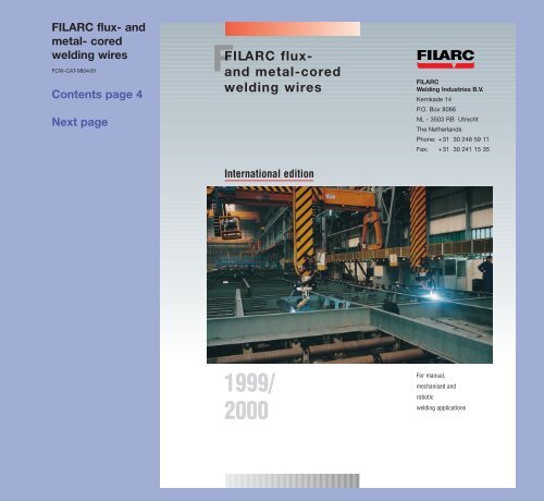
<strong>FILARC</strong> <strong>flux</strong>- andmetal- coredwelding wiresFCW-CAT-9804/01Contents page 4Next pageF<strong>FILARC</strong> <strong>flux</strong>andmetal-coredwelding wiresInternational edition<strong>FILARC</strong>Welding Industries B.V.Kernkade 14P.O. Box 8086NL - 3503 RB UtrechtThe NetherlandsPhone: +31 30 248 59 11Fax: +31 30 241 15 351999/2000For manual,mechanised androboticwelding applications
DIN ISO 9002EN 29002<strong>FILARC</strong> <strong>flux</strong>- andmetal- coredwelding wiresContents page 4Previous pageNext page<strong>FILARC</strong>productsare ISO 9002quality controlledWelding Consumables
<strong>FILARC</strong> <strong>flux</strong>- andmetal- coredwelding wiresIntroductionCoverInside coverContents page 4Previous pageNext pageThis catalogue reviews the internationalrange of <strong>flux</strong>- and metal-cored weldingwires available from <strong>FILARC</strong> WeldingIndustries, Utrecht, The Netherlands.You will find types for practically all steelsand every field of steel fabrication.Index pages 4 to11 categorise coredwires in three ways, enabling you to selectthese according to:• Steel category with products listed innumerical order, see main index page 4.• AWS, EN, and DIN classifications, seepage 8.• Product families in order of yieldstrength/0.2% proof stress for normaland high strength steels, see page 11.Product data pages, listed in the mainindex, provide detailed information oneach cored wire type.A survey of the international programme of<strong>FILARC</strong> stick electrodes is given onpages 134 to 137, including AWS, DINand/or EN classifications. Pages 138 to140 survey the <strong>FILARC</strong> range of solid MIGwires and TIG rods. The list on pages 141to 142 presents the full <strong>FILARC</strong> consumableprogramme as equivalent types.Full information on <strong>FILARC</strong> stick electrodesis given in a separate catalogue. Pleasecontact <strong>FILARC</strong> for your free personal copy.<strong>FILARC</strong> ceramic weld metal supportsfor efficient one-sided welding of root runsare described on pages 129 to 133.ISO 9002 approved QA system.All products in this catalogue are subjectedto ISO 9002 approved quality assurancesystems. They will provide you withoptimal weldability and dependablemechanical properties.<strong>FILARC</strong> Welding Industries have been amember of The <strong>Esab</strong> Group since 1985.Within the Group, <strong>FILARC</strong> specialise in arcwelding consumables, focusing on productsfor heavy industry, typically shipbuilding,offshore fabrication, bridge building,refineries and power plants, includinghydro-power, also earthmoving, constructionand mining equipment.<strong>FILARC</strong> products are internationally distributedthrough <strong>Esab</strong> Group sales organisations,<strong>FILARC</strong> agents and distributors.<strong>FILARC</strong> Welding Industries is responsiblefor general brand management, researchand development, quality assurance,application support and training, alsointernational marketing.Equipment. Although this catalogue dealswith arc welding consumables only,The <strong>Esab</strong> Group offers you the broadestselection of arc welding equipment andauxiliary tools ranging from compact, reliableinvertors to advanced laser cuttinginstallations. For information, contact yournational <strong>Esab</strong> organisation.Cover photo: Fincantieri, Monfalcone, Italy.Robotic welding of ship sections with <strong>FILARC</strong> madecored wires.Due to its policy of continual improvements in itswelding consumables, <strong>FILARC</strong> reserves the right tochange data given in this catalogue without notice.1
<strong>FILARC</strong> <strong>flux</strong>- andmetal- coredwelding wiresGuide to using your<strong>FILARC</strong> catalogueContents page 4Previous pageNext pageThe introductory section of this cataloguecontains indexes and tables to assist youin selecting the <strong>FILARC</strong> <strong>flux</strong>- or metalcoredwire most appropriate for yourapplication.The general content pages on pages 4 to6 give an overview of the complete rangeof <strong>FILARC</strong> cored wires categorized inproduct groups, namely for:• non- and low-alloyed steels• high strength steels• creep resisting steels• stainless steels• dissimilar steels• soft-martensitic steels• hardfacing applicationsDirectly behind the <strong>FILARC</strong> PZ 6XXX typenumber, or above a group of wires belongingto the same category, you will find the<strong>flux</strong> formulation, rutile, basic or metalcored,and a short description of the intendedapplication or most characteristicproperty.Further selection guidance is given by thetable on pages 8 to 10, surveying the mostfrequently used international classifications,and on pages 13 to 17, giving thefull list of international approvals.The survey of <strong>FILARC</strong> products in order ofyield strength given on page 11 may behelpful when selecting cored wires from adesign point of view.Pages 18 to 21 show the EN and AWSclassification systems, explaining the codingused in this catalogue for classifyingindividual products.Introduction to the cored wire groupsThese provide general information andadvice on selecting the cored wire(s) mostappropriate for your application. In manycases there will be options which bringextra productivity compared with multi-purposetypes; for example high speed types(<strong>FILARC</strong> PZ 6XXXHS) with extra high filldegree for downhand and standing fillets.Other examples are rutile types with a fastfreezing slag, giving up to 4kg/h depositionrate (100% duty cycle) in vertical-upwelding.The information in the introduction to eachcored wire section will enable you to see indetail where advantageous options exist.Guide to the product data pagesProduct data pages (starting at page 34)are designed for easy access to all dataneeded for design and fabrication. Theyare always presented in the same formatto aid easy comparison.All international classifications are repeateddirectly below the <strong>FILARC</strong> type number,including the classification conformance.The specification of the cored wire is chosensuch that it satisfies the most importantstandard(s).Note the occasional use of the ~ sign (nearest)behind classifications when a wire notfully meets this classification. This mostlyconcerns the chemical composition.The grey identification bar on the right handside of the product pages surveysinternational approvals, but without theirdenotations. Please refer to pages 13 to 172
<strong>FILARC</strong> <strong>flux</strong>- andmetal- coredwelding wiresGuide to using your<strong>FILARC</strong> catalogue,continuedContents page 4Previous pageNext pagefor detailed information. Where an approvalfor a cored wire has been applied for, buthas not been received at the time this cataloguewas published, this is indicated bythe term "pending". Additional approvals fora given cored wire may arise. Contact<strong>FILARC</strong> or ESAB for the latest information.Further down the identification bar, keyinformation is given on weldability. Thewelding positions for which the cored wireis suited are indicated by icons representingfollowing ASME and EN designations:1G/1FPA4GPEElectrogaswelding2GPC4FPD2FPB5G↑PFOther icons used are:Hardnessfrom 3 rdlayeronwards3G↑/3F↑PF5G↓/6G↓PGCeramicbackingroundgroove3G↓/3F↓PG–(cladding)CeramicbackingrectangulargrooveCurrent & polarity are given further down.The preferred polarity is given in boldtypeface when there is an option for bothDC+ or DC –.The description reviews the cored wire'scharacteristics, also its properties andintended applications.Chemical composition gives the upperand lower limit in weight percentage of themain alloying elements in the weld metal.Certificates specifying actual values of allrelevant chemical elements per lot number,can be made available on request.Shielding gas exactly specifies for whichgas compositions the stated mechanicalproperties can be guaranteed, eg. Ar/15-25%CO 2 . This has become necessarybecause EN 439 may specify a widerrange of gas compositions for a specificcategory than the previous standard forwhich the wires were originally tested.M21 according to Euronorm, for example,covers Ar/CO 2 mixtures with 5-25% CO 2 ,whereas the old DIN specified 15-25% CO 2 .Weld metal hydrogen, given for non- andlow-alloyed types, states typical valuesvalid for diameter size 1.2mm. Samples forhydrogen determination are welded at250A and 15mm stick-out, unless statedotherwise (e.g. high speed types). In addition,pages 26 to 29 give detailed informationon the influence of welding parameterson the hydrogen level (acc. EN758) ofseveral individual cored wires.Deposition data give deposition rates inkg/h at 100% duty cycle, for a characteristicshielding gas within the specified compositionrange.All weld metal mechanical properties oftypes for non- and low-alloyed steels areobtained in tests according to the UnifiedRules of the ship classification societies,AWS and EN. Mechanical properties oftypes for high strength and creep resistantsteels are determined according to toAWS 5.29 specifications, and of stainlesssteel types to AWS 5.22.3
<strong>FILARC</strong> <strong>flux</strong>- andmetal- coredwelding wiresContentsContents page 5Previous pageNext pageIntroduction ..................................................................................................................... 1Guide to using your <strong>FILARC</strong> catalogue ........................................................................ 2Contents .......................................................................................................................... 4Survey of international classifications .......................................................................... 8Index categorised by product family in order of yield strength .............................. 11Survey of international approvals ............................................................................... 13Key to EN classifications ............................................................................................. 18Key to AWS classifications .......................................................................................... 19<strong>FILARC</strong> low-hydrogen cored wires ............................................................................. 22AWS and EN welding positions.................................................................................... 27Welding parameters ...................................................................................................... 28<strong>FILARC</strong> cored wires for non- and low-alloyed steels ............................................... 33Flux- and metal-cored wires for normal temperature applications ................................ 33<strong>FILARC</strong> PZ 6102 metal-cored, thinner plate ................................................... 34<strong>FILARC</strong> PZ 6103 metal-cored, general purpose ............................................. 35<strong>FILARC</strong> PZ 6105R metal-cored, robotic welding .............................................. 36<strong>FILARC</strong> PZ 6111 rutile, fillet welds .................................................................. 37<strong>FILARC</strong> PZ 6112 rutile, weatherproof steels ................................................... 38<strong>FILARC</strong> PZ 6113 rutile, general purpose, ........................................................ 39<strong>FILARC</strong> PZ 6113S rutile, high heat input, CVN –30°C, CO 2 gas ...................... 40<strong>FILARC</strong> PZ 6114 rutile, CVN –40°C ................................................................ 41<strong>FILARC</strong> PZ 6114S rutile, CVN –40°C, CO 2 gas ................................................ 42High speed (HS) cored wires for high deposition welding ............................................. 45<strong>FILARC</strong> PZ 6103HS metal-cored ......................................................................... 48<strong>FILARC</strong> PZ 6111HS rutile ..................................................................................... 49<strong>FILARC</strong> PZ 6130HS basic .................................................................................... 50<strong>FILARC</strong> PZ 6137EG basic, electrogas welding .................................................... 51Flux- and metal-cored wires for low-temperature applications ..................................... 53<strong>FILARC</strong> PZ 6104 metal-cored, CVN –50°C ..................................................... 54<strong>FILARC</strong> PZ 6115 rutile, CVN –50°C, sea water corrosion .............................. 55<strong>FILARC</strong> PZ 6116S rutile, CVN –60°C, CTOD tested, CO 2 gas ......................... 564
<strong>FILARC</strong> <strong>flux</strong>- andmetal- coredwelding wiresContents page 4Contents page 6Previous pageNext page<strong>FILARC</strong> PZ 6125 basic, CVN –60°C, CTOD tested ........................................ 57<strong>FILARC</strong> PZ 6129Ni basic, CVN –60°C ............................................................... 58<strong>FILARC</strong> PZ 6138 rutile, CVN –50°C, CTOD tested ......................................... 59<strong>FILARC</strong> PZ 6140 basic, CVN –60°C, CTOD tested ........................................ 60<strong>FILARC</strong> <strong>flux</strong>-cored wires for high strength steels .......................................................... 63<strong>FILARC</strong> PZ 6145 basic, Rp0.2, min. 500N/mm 2 ............................................. 65<strong>FILARC</strong> PZ 6146 basic, Rp0.2, min. 550N/mm 2 ............................................. 66<strong>FILARC</strong> PZ 6147 basic, Rp0.2, min. 620N/mm 2 ............................................. 67<strong>FILARC</strong> PZ 6148 basic, Rp0.2, min. 690N/mm 2 ............................................. 68<strong>FILARC</strong> PZ 6149 basic, Rp0.2, min. 890N/mm 2 ............................................. 69<strong>FILARC</strong> <strong>flux</strong>-cored wires for creep resisting steels ........................................................ 71<strong>FILARC</strong> PZ 6201 basic, 0.5Cr/0.5Mo-alloyed steels ....................................... 74<strong>FILARC</strong> PZ 6202 basic, 0.5Mo-alloyed steels ................................................. 75<strong>FILARC</strong> PZ 6203 basic, 2.25Cr/1.0Mo-alloyed steels ..................................... 76<strong>FILARC</strong> PZ 6204 basic, 5.0Cr/0.5Mo-alloyed steels ....................................... 77<strong>FILARC</strong> PZ 6205 basic, 1.25Cr/0.5Mo-alloyed steels ..................................... 78<strong>FILARC</strong> PZ 6222 rutile, 0.5Mo-alloyed steels ................................................. 79<strong>FILARC</strong> PZ 6225 rutile, 1.25Cr/0.5Mo-alloyed steels ..................................... 80<strong>FILARC</strong> metal-cored wires for stainless steels ......................................................... 81<strong>FILARC</strong> PZ 6403 for AISI 316L ....................................................................... 83<strong>FILARC</strong> PZ 6410 for AISI 308L ....................................................................... 84<strong>FILARC</strong> PZ 6414 for AISI 309, AISI 410 .......................................................... 85<strong>FILARC</strong> PZ 6422 for duplex stainless steels ................................................... 86<strong>FILARC</strong> metal-cored wires for dissimilar and armour steels ................................... 87<strong>FILARC</strong> PZ 6414 dissimilar steels ................................................................... 90<strong>FILARC</strong> PZ 6470 for 18Cr, 8Ni, 6Mn-alloyed steels (E307) ............................. 91<strong>FILARC</strong> metal-cored wires for (soft) martensitic steels ........................................... 93<strong>FILARC</strong> PZ 6156 for 13Cr martensitic steels .................................................. 95<strong>FILARC</strong> PZ 6166 for 13Cr/4Ni-alloyed steels .................................................. 96<strong>FILARC</strong> PZ 6176 for 17Cr/5Ni-alloyed steels .................................................. 975
<strong>FILARC</strong> <strong>flux</strong>- andmetal- coredwelding wiresContents, continuedContents page 4Contents page 5Previous pageNext page<strong>FILARC</strong> gas- and self-shielded cored wires for hardfacing ..................................... 99<strong>FILARC</strong> PZ 6152/PZ 6352 HRC 27-36, moderate abrasion, heavy shocks ................ 104<strong>FILARC</strong> PZ 6153/PZ 6353 HRC 43-52, moderate abrasion, moderate shocks .......... 105<strong>FILARC</strong> PZ 6154/PZ 6354 HRC 50-60, severe impact and abrasion ......................... 106<strong>FILARC</strong> PZ 6155/PZ 6355 HRC 55-52, high abrasion, medium impact ..................... 107<strong>FILARC</strong> PZ 6159 HRC 49-55, tool repairs, hot working ............................... 108<strong>FILARC</strong> PZ 6163 HRC 36-45, high warm hardness ..................................... 109<strong>FILARC</strong> PZ 6165 HRC 58-62, low stress abrasion ....................................... 110<strong>FILARC</strong> PZ 6168 HRC 62-64, low stress abrasion up to 700°C .................. 111<strong>FILARC</strong> PZ 6358 HRC 55-65, work hardening ............................................. 112<strong>FILARC</strong> PZ 6415 Buffer layers ....................................................................... 113<strong>FILARC</strong> packaging details and storage recommendations ................................... 115Health and Safety ....................................................................................................... 121<strong>FILARC</strong> ceramic weld metal supports ..................................................................... 129<strong>FILARC</strong> international range of arc welding electrodes .......................................... 134<strong>FILARC</strong> international range of MIG solid wires and TIG rods ............................... 138List of equivalent <strong>FILARC</strong> arc welding consumables ............................................. 1416
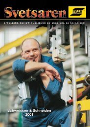
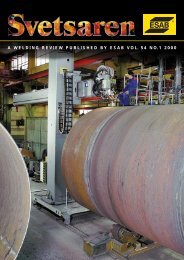
<strong>FILARC</strong> <strong>flux</strong>- andmetal- coredwelding wiresContents page 4Previous pageNext pageSvedala Compaction Equipment, Karlskrona, Sweden.Use of PZ6105R, a metal-cored wire specially developedfor robotic welding, for the fabrication of framesof vibratory road compactors.Important wire properties are a good penetration andtie-in, necessary to avoid fatigue cracking, excellentfeedability, and smooth arc ignition without burn-backproblems and low spatter.Shown here is CA152, a universal frame for variousDynapac compactors. Clearly visible is the characteristicregular frequency at which slag islands are formed, resultingfrom very stable arc properties. The close-up(bottom) reveals an excellent weld appearance with easilyremovable slag.7
<strong>FILARC</strong> <strong>flux</strong>- andmetal- coredwelding wiresSurvey of international classificationsContents page 4The table below surveys the most frequently used international classifications.<strong>FILARC</strong> cored wire types are listed in numerical order (~ = nearest).<strong>FILARC</strong> type AWS EN 758-97Previous pageNext pageNon- and low-alloyed steelsFor normal temperature applications<strong>FILARC</strong> PZ 6102 A5.18-93: E70C-6M H4 T 46 4 M M 2 H5<strong>FILARC</strong> PZ 6103 A5.18-93: E70C-GM H4 T 42 2 M M 2 H5<strong>FILARC</strong> PZ 6105R A5.18-93: E70C-6M H4 T 42 4 M M 3 H5<strong>FILARC</strong> PZ 6111 A5.20-95: E70T-1 H8 ~ T 42 2 1Ni R C 3 H10E70T-1M H8 ~T 46 2 1Ni R M 3 H10<strong>FILARC</strong> PZ 6112 A5.29-80: E71T1-G T 42 2 Z P C 1 H5T 46 2 Z P M 1 H10<strong>FILARC</strong> PZ 6113 A5.20-95: E71T-1 H4 T 42 2 P C 1 H5E71T-1M H8T 46 2 P M 1 H10<strong>FILARC</strong> PZ 6113S A5.20-95: E71T-9 H4 T 46 3 P C 2 H5<strong>FILARC</strong> PZ 6114 A5.20-95: E71T-1MJ H4 T 46 4 P M 1 H5<strong>FILARC</strong> PZ 6114S A5.20-95: E71T-1J H4 T 46 4 P C 1 H5High filling degree types for high speed welding<strong>FILARC</strong> PZ 6103HS A5.18-93: E70C-GM H4 T 42 2 M M 3 H5<strong>FILARC</strong> PZ 6111HS A5.20-95: E70T-1 H8 ~ T 42 2 1Ni R C 3 H10E70T-1M H8 ~T 46 2 1Ni R M 3 H10<strong>FILARC</strong> PZ 6130HS A5.20-95: E70T-5J H4 T 42 4 B C 5 H5E70T-M5J H4T 42 4 B M 3 H5<strong>FILARC</strong> PZ 6137EG A5.26-91: EG72T-Ni1 –For low-temperature applications<strong>FILARC</strong> PZ 6104 A5.18-93: E70C-GM H4 T 42 5 Z M M 2 H5<strong>FILARC</strong> PZ 6115 A5.29-80: E81T1-Ni2 T 50 5 2Ni P M 2 H58
<strong>FILARC</strong> <strong>flux</strong>- andmetal- coredwelding wiresSurvey of international classifications,continuedContents page 4<strong>FILARC</strong> type AWS EN 758-97Previous pageNext page<strong>FILARC</strong> PZ 6116S A5.29-80: E81T1-K2 T 46 6 1.5Ni P C 1 H5<strong>FILARC</strong> PZ 6125 A5.29-80: E71T5-G T 42 6 1Ni B M 1 H5<strong>FILARC</strong> PZ 6129Ni A5.20-95: E71T-5J H4 ~ T 42 6 Z B C 1 H5E71T-5MJ H4 ~ T 42 6 Z B M 1 H5<strong>FILARC</strong> PZ 6138 A5.29-80: E81T1-Ni1 T 46 5 1Ni P M 1 H5<strong>FILARC</strong> PZ 6140 A5.29-80: E81T5-Ni2 ~ T 42 6 2Ni B C 1 H5T 42 6 2Ni B M 1 H5High strength steels<strong>FILARC</strong> PZ 6145 A5.29-80: E81T5-G T 50 5 Mn1Ni B M 1 H5prEN12535-96<strong>FILARC</strong> PZ 6146 A5.29-80: E91T5-K2 T 55 5 Z B M 2 H5<strong>FILARC</strong> PZ 6147 A5.29-80: E101T5-K3 T 62 5 Mn2NiMo B M 2 H5<strong>FILARC</strong> PZ 6148 A5.29-80: E111T5-K4 T 69 5 Mn2NiCrMo B M 2 H5<strong>FILARC</strong> PZ 6149 A5.29-80: E121T5-G T 89 5 Z B M 2 H5 ~Creep resisting steels prEN12071 DIN 8575<strong>FILARC</strong> PZ 6201 – T CrMo1 B M 2 H5 ~ SG CrMo1<strong>FILARC</strong> PZ 6202 A5.29-95: E71T5-A1 T Mo B M 2 H5 SG Mo<strong>FILARC</strong> PZ 6203 A5.29-95: E91T5-B3 ~ T CrMo2 B M 2 H5 SG CrMo2<strong>FILARC</strong> PZ 6204 A5.22-95: E502T1-4 T CrMo5 B M 2 H5 SG CrMo5<strong>FILARC</strong> PZ 6205 A5.29-95: E81T5-B2 T CrMo1 B M 2 H5 ~ SG CrMo1 ~<strong>FILARC</strong> PZ 6222 A5.29-95: E81T1-A1 T Mo R M 2 H10 ~ SG Mo ~<strong>FILARC</strong> PZ 6225 A5.29-95: E81T1-B2 T CrMo1 R M 2H10 ~ SG CrMo1 ~9
<strong>FILARC</strong> <strong>flux</strong>- andmetal- coredwelding wiresSurvey of international classifications,continuedContents page 4Previous pageNext page<strong>FILARC</strong> type AWS DIN 8556/Werkst.nr.Metal-cored wires for stainless steels<strong>FILARC</strong> PZ 6403 A5.9-93: EC316L ~ SG 19 12 3 L /1.4430<strong>FILARC</strong> PZ 6410 A5.9-93: EC308L ~ SG 19 9 L /1.4316<strong>FILARC</strong> PZ 6414 A5.9-93: EC309L SG 23 12 L /1.4332<strong>FILARC</strong> PZ 6422 A5.9-93: EC2209 SG 22 9 3 L /1.4462~Metal-cored wires for dissimilar and armour steels<strong>FILARC</strong> PZ 6470 A5.9-93: EC307~ SG 18 8 Mn/1.4370Cored wires for soft martensitic steelsprEN12073<strong>FILARC</strong> PZ 6156 A5.9-93: EC410 ~ SG 13 1/1.4008 –<strong>FILARC</strong> PZ 6166 A5.9-93: EC410NiMo ~ SG 13 4/1.4351 T 13 4 M 2~<strong>FILARC</strong> PZ 6176 – –Cored wires for hardfacing DIN 8555<strong>FILARC</strong> PZ 6152/PZ 6352 – MF1-300P<strong>FILARC</strong> PZ 6153/PZ 6353 – MF1-45<strong>FILARC</strong> PZ 6154/PZ 6354 – MF6-55GP<strong>FILARC</strong> PZ 6155/PZ 6355 – MF6-60G<strong>FILARC</strong> PZ 6159 – MF3-50T<strong>FILARC</strong> PZ 6163 – MF5-400GC<strong>FILARC</strong> PZ 6165 – MF10-60C<strong>FILARC</strong> PZ 6168 – MF10-65GRPZ<strong>FILARC</strong> PZ 6358 – MF8-250KP<strong>FILARC</strong> PZ 6415 A5.22: E309T-2 –10
<strong>FILARC</strong> <strong>flux</strong>- andmetal- coredwelding wiresIndex categorised byproduct family in orderof yield strengthContents page 4Previous pageNext pageThe table below surveys cored wires for normal and high strength steel using the yieldstrength or 0.2% proof stress as a design criterion. The tensile strength and the lowest47J CVN temperature are given as well, but not in arithmetical order. All mechanical dataare all weld metal properties in the as-welded condition, using M21 or CO 2 shielding gas.<strong>FILARC</strong> type Rp Re Rm T CVN[MPa] [Mpa] ≥47J [°C]M21 CO 2 M21 CO 2 M21 CO 2PZ 6103 – – ≥420 – 510-600 – –20PZ 6105R – – ≥420 – 510-600 – –40PZ 6114S – – – ≥420 – 540-640 –40PZ 6103HS – – ≥420 – 510-600 – –20PZ 6130HS – – ≥420 ≥420 545-630 510-580 –40PZ 6137EG – – – ≥420 – 540-650 –20PZ 6104 – – ≥420 – 520-620 – –50PZ 6125 ≥420 – – – 510-600 – –60PZ 6129Ni – – ≥420 ≥420 510-600 510-600 –60PZ 6140 ≥420 ≥420 – – 500-620 500-620 –60PZ 6102 – – ≥460 – 550-650 – –40PZ 6111 – – ≥460 ≥420 545-630 510-580 –20PZ 6111HS – – ≥460 ≥420 545-630 510-580 –20PZ 6112 ≥460 ≥440 – – 550-640 520-610 –20PZ 6113 – – ≥460 ≥420 550-640 510-590 –20PZ 6113S – – – ≥460 – 550-650 –30PZ 6114 – – ≥460 – 550-640 – –40PZ 6116S – ≥470 – – – 550-650 –60PZ 6115 ≥500 – – – 560-680 – –50PZ 6138 ≥500 – – – 550-650 – –50PZ 6145 ≥500 – – – 580-680 – –50PZ 6146 ≥550 – – – 630-760 – –50PZ 6147 ≥620 – – – 700-830 – –50PZ 6148 ≥690 – – – 770-900 – –50PZ 6149 ≥890 – – – 950-1050 – –2011
<strong>FILARC</strong> <strong>flux</strong>- andmetal- coredwelding wiresNotesContents page 4Previous pageNext page................................................................................................................................................................................................................................................................................................................................................................................................................................................................................................................................................................................................................................................................................................................................................................................................................................................................................................................................................................................................................................................................................................................................................................................................................................................................................................................................................................................................................................................................................................................................................................................................................................................................................................................................................................................................................................................................................................................................................................................................................................................................................................................................................................................................................................................................................................................................................................................................................................................................................................................................................................................................................................................................................................................................................................................................................................................................................................................................................................................................................................................................................................................................................................................................................................................................................................................................................................................................................................................................................................................................................................................................................................................................................................................................................................................................................................................................................................................................................................................................................................................................................................................................................................................................12
<strong>FILARC</strong> <strong>flux</strong>- andmetal- coredwelding wiresSurvey of international approvalsContents page 4Previous pageNext pageTables on the following pages give a completeoverview of approvals granted byThe Ship Classification Societies andother approval authorities.Approvals are repeated on the productdata pages for individual products, butwithout denotations.AbbreviationsABS : American Bureau of ShippingBV : Bureau VeritasContr. : ControlasDB : Deutsche BundesbahnDNV : Det Norske VeritasDSGLLRMRSPRSRINATÜVCRSCCS: FORCE Inst. (Danish Stand.): Germanischer Lloyd: Lloyd’s Register of Shipping: Maritime Register of Shipping(Russia): Polski Rejestr Statków: Registro Italiano Navale: Technischer Überwachungsverein: Croatian Register of Shipping: China Classification Society13
<strong>FILARC</strong> <strong>flux</strong>- andmetal- coredwelding wiresSurvey of international approvals,continuedContents page 4Cored wire ABS BV Con- DB DNV Forcetype trolas EN758Non- and low-alloyed steelsPrevious pageNext pageNormal temperature applications<strong>FILARC</strong> PZ 6102 3SA, 3YSA SA3 3YMHH 0771 42.105.09 IV YMS(H10) T 46 4 M M 2 H10<strong>FILARC</strong> PZ 6103 3SA, 3YSA SA3 3YMHH 0428 42.105.05 III YMS(H10) T 46 4 M M 2 H5<strong>FILARC</strong> PZ 6105R 4Y400 SA3 3YMHH – approved IV 4Y40(H5) –<strong>FILARC</strong> PZ 6111 2 3SA, 3YSA SA3 3YMHH 0751 42.105.06 III YMS(H10) T 46 2 1Ni R M 3 H10<strong>FILARC</strong> PZ 6111 3 3SA, 3YSA SA3 3YMHH 0751 42.105.06 III YMS(H10) T 46 2 1Ni R C 3 H10<strong>FILARC</strong> PZ 6112 – – – 42.105.13 – –<strong>FILARC</strong> PZ 6113 2 3SA, 3YSA SA3 3YMHH 0452 42.105.07 III YMS(H10) T 46 2 P M 1 H10<strong>FILARC</strong> PZ 6113 3 3SA, 3YSA SA3 3YMHH 0452 42.105.07 III YMS(H10) T 42 2 P C 1 H10<strong>FILARC</strong> PZ 6113S 3SAH, 3YSAHH 1 SA 3YMHH 1 – – III YMS(H10) 1 T 46 3 P C 2 H10<strong>FILARC</strong> PZ 6114 4YSA H5 SA 3YMHH – pending IV Y40MS(H5) T 46 4 P M 1 H5<strong>FILARC</strong> PZ 6114S 4YSA H5 SA 3YMHH – pending IV Y40MS(H5) T 46 4 P C 1 H5High filling degree types for high speed welding<strong>FILARC</strong> PZ 6103HS 3SA, 3YSA H5 SA 3YMHH – pending III Y40MS(H5) T 42 2 M M 3 H5<strong>FILARC</strong> PZ 6111HS 2 3SA, 3YSA H5 SA 3YMHH – pending II/III Y40MS(H5) T 42 2 1Ni R M 3 H10<strong>FILARC</strong> PZ 6111HS 3 3SA, 3YSA H5 SA 3YMHH – pending II/III Y40MS(H5) T 42 2 1Ni R C 3 H10<strong>FILARC</strong> PZ 6130HS 2 3SA, 3YSA 4 SA3 3YMHH 4 0989 42.105.03 IV YM(H10) -<strong>FILARC</strong> PZ 6130HS 3 3SA, 3YSA 4 SA3 3YMHH 4 0989 42.105.03 IV YMS(H10) T 38 4 B C 5 H10<strong>FILARC</strong> PZ 6137EG 3SA, 3YSA H5 AV, 3Y, HH – – II Y40(H5) –Low-temperature applications<strong>FILARC</strong> PZ 6104 3SA, 3YSA SA 3YMHH 0468 42.105.10 IV YMS(H10) T 42 4 Z M M 2 H5<strong>FILARC</strong> PZ 6115 – – – – IV Y46MS(H15)–<strong>FILARC</strong> PZ 6116S 3SAH, 3YSAHH 5 SA 3YMHH 5 – – V YMS(H10) –<strong>FILARC</strong> PZ 6125 3SA, 3YSA 5 SA3 3YMHH 0956 42.105.12 V Y40MS(H5) T 42 6 1Ni B M 1 H5<strong>FILARC</strong> PZ 6129Ni 2 3SA, 3YSA 6 SA 3YMHH 0313 – V YMS(H10) T 42 4 Z B M 1 H5<strong>FILARC</strong> PZ 6129Ni 3 3SA, 3YSA 6 SA 3YMHH 0313 – V YMS(H10) T 42 4 Z B C 1 H5<strong>FILARC</strong> PZ 6138 3SA, 3YSA 7 SA3 3YMHH 0925 42.105.08 V Y42MS(H5) T 46 5 1Ni P M 1 H10High strength steels<strong>FILARC</strong> PZ 6145 – – – – IV Y50MS(H5) –<strong>FILARC</strong> PZ 6148 – – – – – –See page 16 for foot notes14
<strong>FILARC</strong> <strong>flux</strong>- andmetal- coredwelding wiresSurvey of international approvals,continuedContents page 4Cored wire GL LR MRS PRS RINA TÜV UDT CRS CCStypeNon- and low-alloyed steelsPrevious pageNext pageNormal temperature applications<strong>FILARC</strong> PZ 6102 4YHHS 3S 3YS 4Y42HHS – – 4901 X – 4Y42<strong>FILARC</strong> PZ 6103 3YHHS 3S 3YS 3Y42HHS 3YH10S SG 52 2 4461 X – –<strong>FILARC</strong> PZ 6105R 4Y40H5S 4Y40 H5 – – SG52 3 approved – – –<strong>FILARC</strong> PZ 6111 2 3YHHS 3S 3YS 3YHHS 3YH10S – 3013 X 3YH10S 3Y40<strong>FILARC</strong> PZ 6111 3 3YHHS 3S 3YS 3YHHS 3YH10S – 3013 X 3YH10S 3Y40<strong>FILARC</strong> PZ 6112 – – – – – 6767 X – –<strong>FILARC</strong> PZ 6113 2 3YHHS 3S 3YS 3YHHS 3Y H10S SG 52 3 4902 X 3YH10S 3Y40<strong>FILARC</strong> PZ 6113 3 3YHHS 3S 3YS 3YHHS 3Y H10S SG 52 2 4902 X 3YH10S 3Y40<strong>FILARC</strong> PZ 6113S 4Y42H10S 3S 3YS 3YHHS 3Y H10S SG 52 3 7085 X 4YH10S 3Y42<strong>FILARC</strong> PZ 6114 4YH5S 3S 4Y40S 4Y42HHS 4YH5S – X X 4YH5S 4Y42<strong>FILARC</strong> PZ 6114S 4YH5S 3S 4Y40S 4Y42HHS 4YH5S – X X 4YH5S 4Y42High filling degree types for high speed welding<strong>FILARC</strong> PZ 6103HS 3YH5S 3S 3YS 3Y42HHS 3YH5S – X X – –<strong>FILARC</strong> PZ 6111HS 2 3YH5S 3S 3YS 3YHHS 3YH5S – X X – 3Y40<strong>FILARC</strong> PZ 6111HS 3 3YH5S 3S 3YS 3YHHS 3YH5S – X X – 3Y40<strong>FILARC</strong> PZ 6130HS 4YHHS 2 3M 4Y40M 4Y42HHS 3YH10S – 5870 X – –<strong>FILARC</strong> PZ 6130HS 4YHHS 3 3M 4Y40S 4Y42HHS 3YH10S – 327 X – –<strong>FILARC</strong> PZ 6137EG 3YV 3Y 3Y42HHS 3YH5V – 7067 X – –Low-temperature applications<strong>FILARC</strong> PZ 6104 4YHHS 3S 3YS 4Y42HHS – – 5477 X – –<strong>FILARC</strong> PZ 6115 – – 4Y42HHS – – – – – –<strong>FILARC</strong> PZ 6116S 6YH10S 3S 5Y40S 5Y42HHS 3YH10S SG 52 5 – – – 1.5Ni<strong>FILARC</strong> PZ 6125 6YHHS 3S 5Y40S 5Y42HHS 3YH10S SG 52 5 5648 X – 0.5Ni<strong>FILARC</strong> PZ 6129Ni 2 5YHHS 3S 4Y40S 5Y42HHS 3YH10S – 4228 X – –<strong>FILARC</strong> PZ 6129Ni 3 5YHHS 3S 4Y40S 5Y42HHS 3YH10S – 4228 X – –<strong>FILARC</strong> PZ 6138 6YH10S 7 3S 5Y40S 5Y42HHS 3YH10S SG 52 5 4903 X – –High strength steels<strong>FILARC</strong> PZ 6145 – – – – – 6791 X – –<strong>FILARC</strong> PZ 6148 – – – – – X – – –See page 16 for foot notes15
<strong>FILARC</strong> <strong>flux</strong>- andmetal- coredwelding wiresSurvey of international approvals,continuedContents page 4Cored wire ABS BV Con- DB DNV DStype trolas 317Creep resisting steelsPrevious pageNext page<strong>FILARC</strong> PZ 6201 – – 436 – – –<strong>FILARC</strong> PZ 6202 – – 839 – – –<strong>FILARC</strong> PZ 6203 – – 755 – – –<strong>FILARC</strong> PZ 6204 – – 224 – – –<strong>FILARC</strong> PZ 6205 – – 617 – – –<strong>FILARC</strong> PZ 6222 – – 1320 – – –<strong>FILARC</strong> PZ 6225 – – X – – –Metal-cored wires for stainless steels<strong>FILARC</strong> PZ 6403 – – 1043 43.105.01 316L MS –<strong>FILARC</strong> PZ 6410 – – 869 43.105.02 – –<strong>FILARC</strong> PZ 6414 – – 36 – – –Metal-cored wires for dissimilar, armour steels<strong>FILARC</strong> PZ 6470 – – – 43.105.03 – –1 ISO-V min. 54J at –30°C2 For M213 For CO 24 ISO-V min. 47J at –40°C5 low-temp. application down to –60°C6 ISO-V min. 60J at –40°C7 ISO-V min. 35J at –60°C8 Ø1.6mm in M11 gas according to DIN 325269 Ø1.6mm in M23 gas10 For Ø1.6mm only11 For use in M11, M12, M21 gas according to DIN 32526X Approved, no grade notation or certificate number.16
<strong>FILARC</strong> <strong>flux</strong>- andmetal- coredwelding wiresSurvey of international approvals,continuedContents page 4Cored wire GL LR MRS PRS RINA TÜV OthertypeCreep resisting steelsPrevious pageNext page<strong>FILARC</strong> PZ 6201 – – – – – – –<strong>FILARC</strong> PZ 6202 – – – – – 7068 –<strong>FILARC</strong> PZ 6203 – – – – – 7069 –<strong>FILARC</strong> PZ 6204 – – – – – – –<strong>FILARC</strong> PZ 6205 – – – – – 7070 –<strong>FILARC</strong> PZ 6222 – – – – – 7071 –<strong>FILARC</strong> PZ 6225 – – – – – – –Metal-cored wires for stainless steels<strong>FILARC</strong> PZ 6403 – 316L – – – 3171 11 –<strong>FILARC</strong> PZ 6410 – – – – – 3014 –<strong>FILARC</strong> PZ 6414 – – – – – – –Metal-cored wires for dissimilar steels, armour steels<strong>FILARC</strong> PZ 6470 – – – – – 4335 –17
<strong>FILARC</strong> <strong>flux</strong>- andmetal- coredwelding wiresKey to EN classificationsFor <strong>flux</strong> and metal-cored wiresaccording to EN 758-97Contents page 4T 46 3 1Ni B M 4 H5Previous pageNext pageIndicates tubular wireSymbol for tensile propertiesSym- min. yield strength 1) tensile strength min. elonbol(N/mm 2 ) (N/mm 2 ) gation 2) (%)35 355 440-570 2238 380 470-600 2042 420 500-640 2046 460 530-680 2050 500 560-720 181) For the yield strength the lower yield (R el ) shall be usedwhen yielding occurs, otherwise the 0.2% proof stress(R p0.2 ) shall be used2) L o = 5dSymbol for impact propertiesSymbolMinimum av. impact energy 47J°CZno requirementsA +200 +02 –203 –304 –405 –506 –60Symbol for chemical composition of weld metal with min. yieldSymbol for diffusible hydrogen (optional)Symbol Max. hydrogen content, ml/100gdeposited weld metalH 5 5H 10 10H 15 15Symbol for the welding positionThe welding positions are symbolised by a digit designating thepositions for which the electrode is tested according toEN 1597-3 as follows:1: all positions2: all positions, except vertical downward3: flat butt weld, flat fillet weld, horizontal/vertical fillet weld4: flat butt weld, flat fillet weld5: as 3 and recommended vertical down weldingSymbol for shielding gasThe symbol is based on the classification of shielding gases in EN439. The testing shall be performed with the shielding gas M2without helium, for mixed gases, symbolised M, or with carbondioxide, symbolised C.strength up to 500 N/mm 2 Sym- Slag Single (S) ShieldingAlloy Chemical composition 1)symbol%Mn Mo Nino symbol 2.0 – –Mo 1.4 0.3 - 0.6 –MnMo >1.4 - 2.0 0.3 - 0.6 –1Ni 1.4 – 0.6 - 1.22Ni 1.4 – 1.8 - 2.63Ni 1.4 – 2.6 - 3.8Mn1Ni >1.4 - 2.0 – 0.6 - 1.21NiMo 1.4 0.3 - 0.6 0.6 - 1.2ZAny other agreed composition1) If not specified: Mo
<strong>FILARC</strong> <strong>flux</strong>- andmetal- coredwelding wiresKey to AWS classificationsContents page 4Previous pageNext pageThe majority of the products described in this catalogue are classified according the followingAWS classification systems. Note that metal-cored types for carbon steel andstainless steel are included in the AWS classifications for solid wires and rods, whereasother cored wire types are covered by separate AWS classifications.Below, the coding system of these classifications are briefly described, explaining thecoding applying to the cored wires in this catalogue. For further information, readers arereferred to the appropriate AWS specifications.AWS A5.9-95. Specification for solid stainless steel welding wires and rods. This classificationincludes metal-cored wires for stainless steel, referred to as composite metalcoredwelding electrodes.(example: EC309LMo) E X XXX X XXSymbol for electrodeSymbol for solid (R) or composite metal-cored wire electrode (C)Designates all weld metal chemical compositionSuffix "L" when %C
<strong>FILARC</strong> <strong>flux</strong>- andmetal- coredwelding wiresKey to AWS classifications,continuedContents page 4AWS A5.20-95. Specification for carbon steel electrodes for <strong>flux</strong> cored arc welding.It covers all cored wire types, except metal-cored.(example: E71T-1MJ H4) E X X T - X M J - HZPrevious pageNext pageSymbol for electrodeMinimum tensile strength (in psi x 10 000)Welding positions of the electrode0 = flat and horizontal position only1 = all positionsIndicates <strong>flux</strong>-cored electrodeNumber from 1 through 14 or the letter “G” with orwithout an “S” following, referring to the usability ofthe electrode. The “G” indicates that the external shielding,polarity, and impact properties are not specified; the “S”that the electrode is suitable for a weld consisting ofa single pass, only.An “M” indicates that the the electrode is classified using75-80% Ar/balance CO 2 shielding gas. When the “M”does not appear, it signifies that either the shielding gasused for classification is CO 2 or that the product is self-shielded.Optional supplemental designatorsDesignates that the electrode meets the requirements of thediffusible hydrogen test (an optional supplemental test of theweld metal with an average value not exceeding “Z” ml ofH 2 /100g of deposited metal where “Z” is 4, 8, or 16).Designates that the electrode meets 27J at –40°C. Absence ofthe “J” indicates normal impact requirements.20
<strong>FILARC</strong> <strong>flux</strong>- andmetal- coredwelding wiresKey to AWS classifications,continuedContents page 4AWS A5.29-95:. Specification for low-alloy steel electrodes for <strong>flux</strong>-coredarc welding.(example: E71T5-A1) E X X T X - XPrevious pageNext pageSymbol for electrodeMinimum tensile strength in units of 10 000 psiPrimary welding positions for which wire is designed:0 = flat and horizontal1 = all positionsIndicates a <strong>flux</strong> cored wireUsability and performance capabilitiesChemical composition of deposited weld metal21
<strong>FILARC</strong> <strong>flux</strong>- andmetal- coredwelding wires<strong>FILARC</strong> low-hydrogen cored wiresContents page 4Previous pageNext pageLow-hydrogen from <strong>FILARC</strong> cored wiresIntroductionModern thermo-mechanically treated andaccelerated cooled steels, with low hardenability,provide fabricators with usefulopportunities to avoid preheating whenwelding with low-hydrogen consumables.Generally speaking, cored wires link-upvery well with this development in steelproduction, because they have a muchbetter hydrogen performance than thestick electrodes they are gradually replacingin today's fabrication practice.This better performance is due to theabsence of hygroscopic binders in the fillingof cored wires, resulting in a muchlower sensitivity to moisture re-absorption.Cored wires generally do not require climatecontrolled storage or re-baking, or aspecial vacuum packaging to avoid these,as with stick electrodes. Some manufacturersare nowadays even able to producerutile cored wires well within the lowest ENhydrogen class H5; a property that is stillunthinkable for equivalent rutile stick electrodes.<strong>FILARC</strong> cored wiresProduction of <strong>FILARC</strong> cored wires uses theunique rolling method; a dry productionprocess which avoids hydrogen containinglubricants. No baking is needed to removethese lubricants, so giving <strong>FILARC</strong> coredwires the characteristic shiny surface.<strong>FILARC</strong>'s technology enables the productionof basic, metal-cored and even rutilecored wires with very low weld metalhydrogen values. The product data pages,starting at page 34 give typical hydrogenvalues for all <strong>FILARC</strong> types for normaltemperaturesteels, low-temperature steels,weather resistant steels, high strengthsteels, creep resistant steels, and for (soft)martensitic stainless steels used for hydroturbine components. Unless otherwise statedthe values are valid for the 1.2mm diametersize, determined at 250A and 15mmstick-out length.Metal-cored and basic <strong>FILARC</strong> types generallygive the lowest weld metal hydrogencontent; mostly around 2ml/100g.Rutile types yield somewhat higher values,generally between 3 and 4ml/100g, but stillwell within EN785 class H5.Hydrogen parameter envelopeThe hydrogen content of weldments maydiffer from the levels obtained under thestandardised test conditions mentionedabove, because welding parameters havea substantial influence. The weld metalhydrogen content increases with higherwelding currents and with shorter stick-outlengths.The influence of welding parameters onthe hydrogen level is visualised in socalled hydrogen parameter envelopes.Next page, this envelope is shown for the<strong>FILARC</strong> PZ 6113; an all-position rutile typeused accross Europe for shipbuilding andgeneral construction. Since it is a wire thatcan be used in both Ar/CO 2 and CO 2 ,envelopes are shown for both gases.It is shown that the H5 limit is only slightlyexceeded for welding currents above 250Aand a short stick-out length; so when usingthe most unfavourable parameter setting.And this is only the case with Ar/CO 2 .The use of CO 2 results in even lower values,which is a commonly observed phenomenonin cored wire welding. The dia-22
<strong>FILARC</strong> <strong>flux</strong>- andmetal- coredwelding wires<strong>FILARC</strong> low-hydrogen cored wires,continuedContents page 4Previous pageNext pageHydrogen parameter envelopes for <strong>FILARC</strong>PZ6113/1.2mm.gram proves that, although a rutile type,PZ 6113 is a very dependable consumablegiving all necessary security.Another multi-purpose type is <strong>FILARC</strong>PZ 6125; an all-position basic wire developedfor offshore fabrication and generalconstruction. It is used in Ar/CO 2 mixedgas. The hydrogen parameter envelope ofthis type confirms a very secure performance,well below the H5 limit for the fullrange of applicable welding currents. Identicalenvelopes are valid for the range ofcored wires for high strength steels(PZ 6145 to PZ 6149) and for the basictypes of the range for creep resistantsteels (PZ 6201 to PZ 6205). These wireshave an identical performance, becausethey are based on PZ 6125.All metal-cored types have a hydrogenperformance comparable with <strong>FILARC</strong>PZ 6125.Hydrogen parameter envelope for <strong>FILARC</strong>PZ6125/1.2mm.<strong>FILARC</strong> PZ6138<strong>FILARC</strong> PZ 6138 is a rutile all-position wirespecifically developed for offshore fabrication,where the use of thick-walled materialscoincides with high restraint and threedimensional stresses. Although these conditionscall for a basic low-hydrogen consumablewith appropriate mechanicalproperties, rutile cored wires are preferredin this industrial segment, because of theirsuperb weldability. Next page, we discussthe performance of PZ 6138 in detail,including sensitivity to moisture reabsorptionduring storage in the original packaging,during unprotected exposure on theshop floor, and during welding.Hydrogen values, determined under theabove mentioned standard Euronorm conditionsare statistically between 1.8 and3.5ml/100g deposited weld metal, whereasits hydrogen parameter envelope shows a23
<strong>FILARC</strong> <strong>flux</strong>- andmetal- coredwelding wires<strong>FILARC</strong> low-hydrogen coredwires, continuedContents page 4Previous pageNext pagedependable performance over the completerange of applicable parameters.Another important feature is the resistanceto moisture reabsorption. Moisture pick-upcan take place during long term storage inthe original packaging (shelf life) and duringunprotected exposure on the shopfloorafter opening the packaging.Accelerated shelf life tests under anatmosphere of 80%RH and 26.6°C, a forEurope severe climatic condition equalingan air moisture content of 20mg/m3, revealan initial increase in hydrogen content flatteningout as exposure times lengthen, forboth packed and unpacked wire.Evidently, this condition is unrealisticallysevere. Under normal warehouse conditionsshelf life is regarded as practicallyunlimited, whereas moisture pick-up onthe shopfloor is minimal when care is takento return partly used spools to theiroriginal packaging (see storage recommendations).The sensitivity to the air moisture contentduring welding is tested in a climate roomunder atmospheric conditions of 8, 20 and35mg moisture/m3. The latter equals anextreme tropical condition. As may beexpected from a gas shielded cored wire,PZ 6138 is practically insensitive to the airmoisture content.The same applies to PZ6125. For comparison,a 8016-G basic MMA electrode hasbeen tested as well, showing a substantialincrease in weld metal hydrogen content.The above diagrams reveal why <strong>FILARC</strong>PZ6138 has earned an excellent reputationin offshore fabrication and plays a keyrole in QA programmes aiming at crackfreewelding without, or with minimal preheating.Hydrogen parameter envelope for <strong>FILARC</strong>PZ6138/1.2mm in Ar/20%CO 2 .Accelerated shelf life tests for PZ6138/1.2 exposedpacked and unpacked (80%RH/ 26.6°C).Influence of absolute air moisture content duringwelding for <strong>FILARC</strong> PZ6138, PZ6125 and anE8016-G MMA electrode.24
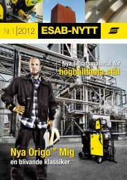
<strong>FILARC</strong> <strong>flux</strong>- andmetal- coredwelding wiresContents page 4Previous pageNext pageBelleli Offshore, Taranto, Italy.The fabrication of hulls for Shell tension leg platforms for service in the deep water oil and gasfields in the Gulf of Mexico. The low-hydrogen properties of PZ6138 all-position rutile cored wirewas a crucial element in a QA programme performed by Belleli and Shell to reduce or avoid preheatingand so obtain substantial savings in fabrication costs.25
<strong>FILARC</strong> <strong>flux</strong>- andmetal- coredwelding wiresNotesContents page 4Previous pageNext page................................................................................................................................................................................................................................................................................................................................................................................................................................................................................................................................................................................................................................................................................................................................................................................................................................................................................................................................................................................................................................................................................................................................................................................................................................................................................................................................................................................................................................................................................................................................................................................................................................................................................................................................................................................................................................................................................................................................................................................................................................................................................................................................................................................................................................................................................................................................................................................................................................................................................................................................................................................................................................................................................................................................................................................................................................................................................................................................................................................................................................................................................................................................................................................................................................................................................................................................................................................................................................................................................................................................................................................................................................................................................................................................................................................................................................................................................................................................................................................................................................................................................................................................................................................................26
<strong>FILARC</strong> <strong>flux</strong>- andmetal- coredwelding wiresAWS and EN welding positionsContents page 4Previous pageNext page1G/PA2G/PC3G ↑↓/PF & PG4G/PE5G ↑↓/PF & PG6G ↑↓/HL04545°1F/PA2F/PB3F ↑↓/PF & PG 4F/PD27
<strong>FILARC</strong> <strong>flux</strong>- andmetal- coredwelding wiresWelding parametersContents page 4Previous pageNext pageThe table below surveys three major families in the range of cored wires for: non-alloyedsteels, low-temperature steels, high strength steels, and creep resistant steels. Thesefamilies are all-position rutile, all-position basic, and all-position metal-cored.Observe following guidelines regarding current and polarity:- All-position rutile types: DC+. Increase arc voltage by 1-2V when using CO 2- All-position basic types: DC–- All position metal-cored types: DC+All-position rutile types All-position basic types All-position metal-cored typesType Shielding gas Type Shielding gas Type Shielding gasFor non-alloyed steels/low-temperature steelsPZ 6113 Ar/20%CO 2 PZ 6125 Ar/20CO 2 PZ 6102 Ar/20%CO 2CO 2PZ 6113S CO 2 PZ 6103 Ar/20%CO 2PZ 6114 Ar/20%CO 2 PZ 6104 Ar/20%CO 2PZ 6114S CO 2 PZ 6105R Ar/20%CO 2PZ 6115 Ar/20%CO 2PZ 6116S CO 2PZ 6138 Ar/20%CO 2For high tensile steelsPZ 6145 Ar/20%CO 2PZ 6146 Ar/20%CO 2PZ 6146 Ar/20%CO 2PZ 6148 Ar/20%CO 2PZ 6149 Ar/20%CO 2For creep resistant steelsPZ 6222 Ar/20%CO 2 PZ 6201 Ar/20%CO 2PZ 6225 Ar/20%CO 2 PZ 6202 Ar/20%CO 2PZ 6203 Ar/20%CO 2PZ 6204 Ar/20%CO 2PZ 6205 Ar/20%CO 2For weather resistant steelsPZ 6112 Ar/20%CO 2The next three pages give, for each family, welding parameter settings for various weldingpositions that are valid for all types belonging to that family, based on Ar/20%CO 2shielding gas.28
<strong>FILARC</strong> <strong>flux</strong>- andmetal- coredwelding wiresWelding parameters, continuedAll-position rutile cored wiresFor relevant types see page 28Contents page 4Previous pagePA/1G, 1FØ Current V wire Voltage[mm] [A] [m/min] [V]1.2 170-190 6.0-08.0 23-26 root*180-280 6.0-12.0 25-30 fill1.4 180-200 4.0-04.5 23-26 root*190-340 4.5-10.5 24-32 fill1.6 not recommended root210-400 4.5-10.5 25-35 fillPB/2FØ Current V wire Voltage[mm] [A] [m/min] [V]1.2 180-300 6.0-14.0 24-311.4 190-340 4.5-10.5 24-321.6 200-380 4.0-09.0 25-33PC/2GNext page Ø Current V wire Voltage[mm] [A] [m/min] [V]1.2 170-190 6.0-08.5 23-26 root*180-260 6.0-10.0 25-29 fill1.4 180-210 4.0-04.5 23-27 root*190-300 4.5-08.5 24-30 fill1.6 not recommended root210-320 4.5-08.0 25-33 fillPE/4GØ Current V wire Voltage[mm] [A] [m/min] [V]1.2 not recommended root180-260 6.0-10.0 24-28 fill1.4 not recommended root190-240 4.5-06.0 24-28 fill1.6 not recommended rootPG/3F-downØ Current V wire Voltage[mm] [A] [m/min] [V]1.2 180-220 6.0-9.0 23-261.4 190-230 4.5-6.0 24-281.6 possible, but not recommendedPD/4FØ Current V wire Voltage[mm] [A] [m/min] [V]1.2 180-250 6.0-10.0 23-281.4 190-240 4.5-06.0 24-281.6 220-250 5.0-06.5 24-28PF/3G-up/ 3F-upØ Current V wire Voltage[mm] [A] [m/min] [V]1.2 180-260 6.0-12.0 23-32 root*180-280 6.0-12.0 24-30 fill1.4 180-270 4.0-09.5 23-28 root*190-290 4.5-10.0 24-30 fill1.6 not recommended root220-280 5.0-07.0 24-30 fillH-L000/H-L045/5G-up/6GØ Current V wire Voltage[mm] [A] [m/min] [V]1.2 not recommended root180-280 6.0-9.0 24-28 fill1.4 not recommended root190-240 4.5-6.0 24-28 fill1.6 not recommended root*one-sided root pass on ceramic backing, V-joint. Limit current to 180A (Ø1.2) or 190A(Ø1.4) for positions PA and PC.29
<strong>FILARC</strong> <strong>flux</strong>- andmetal- coredwelding wiresWelding parameters, continuedAll-position basic cored wires;For relevant types see page 28Contents page 4Previous pageNext pagePA/1G,1FØ Current V wire Voltage[mm] [A] [m/min] [V]1.2 180-230 08.0-11.0 22-28 root*240-320 12.5-19.0 28-34 fill1.6 220-260 04.0-05.0 26-28 root*240-380 04.5-12.0 27-36 fillPC/2GØ Current V wire Voltage[mm] [A] [m/min] [V]1.2 170-230 7.0-11.0 21-28 root*190-280 9.0-16.0 23-33 fill1.6 200-240 3.5-04.5 24-26 root*240-270 4.5-05.5 26-30 fillPB/2FØ Current V wire Voltage[mm] [A] [m/min] [V]1.2 240-270 12.5-15.0 28-301.6 240-320 04.5-08.0 30-35PD/4FØ Current V wire Voltage[mm] [A] [m/min] [V]1.2 160-230 6.5-11.0 18-281.6 not recommendedPE/4GØ Current V wire Voltage[mm] [A] [m/min] [V]1.2 not recommended root130-150 4.0-6.5 18-19 fill1.6 not recommendedPF/3G-up/ 3F-upØ Current V wire Voltage[mm] [A] [m/min] [V]1.2 150-180 6.5-8.0 19-22 root*180-200 8.0-9.5 22-25 fill1.6 not recommendedPF/H-L000/5G-upØ Current V wire Voltage[mm] [A] [m/min] [V]1.2 not recommended root130-180 4.0-8.0 18-22 fill1.6 not recommendedH-L045/6GØ Current V wire Voltage[mm] [A] [m/min] [V]1.2 not recommended root130-180 4.0-8.0 18-22 fill1.6 not recommended* one-sided root pass on ceramic backing, V-joint; spray arc. For welding root runs withoutceramic backing, <strong>FILARC</strong> PZ 6129Ni (page 58) is recommended.30
<strong>FILARC</strong> <strong>flux</strong>- andmetal- coredwelding wiresWelding parameters, continuedAll-position metal-cored wiresFor relevant types see page 28Contents page 4Previous pageNext pagePA/1G, 1FØ Current V wire Voltage[mm] [A] [m/min] [V]1.2 090-130 2.0-04.0 16-17 root 1190-210 6.0-08.0 26-28 root*190-350 6.0-17.0 26-36 fill1.4 110-150 1.5-03.0 16-18 root 1220-230 5.0-07.5 27-29 root*220-480 5.0-17.0 27-40 fill1.6 250-270 5.0-06.0 29-31 root*250-470 5.0-13.0 29-40 fillPD/4FØ Current V wire Voltage[mm] [A] [m/min] [V]1.2 190-250 6.0-10.0 26-301.4 210-280 6.5-08.0 28-291.6 not recommendedPE/4GØ Current V wire Voltage[mm] [A] [m/min] [V]1.2 90-110 1.5-2.5 15-17 root 1110-150 2.0-3.5 16-17 fill 11.4 110-135 2.0-2.5 15-16 root 1110-150 2.0-3.0 16-17 fill 11.6 not recommendedPF/H-L000/5G-upØ Current V wire Voltage[mm] [A] [m/min] [V]1.2 80-130 1.5-4.5 15-18 root 190-160 2.0-4.5 17-19 fill 11.4 110-135 2.0-2.5 15-16 root 1110-150 2.0-3.0 16-17 fill 11.6 not recommendedPB/2FØ Current V wire Voltage[mm] [A] [m/min] [V]1.2 190-320 6.0-14.0 26-341.4 220-320 5.0-12.0 27-331.6 250-420 5.0-11.5 29-37PC/2GØ Current V wire Voltage[mm] [A] [m/min] [V]1.2 80-110 1.5-03.5 16-17 root 1190-220 6.0-08.0 26-28 root*190-250 6.0-10.0 26-30 fill1.4 100-150 1.5-03.0 15-17 root 1200-225 5.5-07.0 25-27 root*210-300 6.5-09.5 28-30 fill1.6 not recommendedPF/3G-up/ 3F-upØ Current V wire Voltage[mm] [A] [m/min] [V]1.2 80-130 1.5-4.5 15-18 root 180-130 1.5-4.5 15-18 root 290-160 2.0-4.5 17-19 fill 11.4 100-140 1.5-3.0 15-18 root 1100-140 1.5-3.5 15-18 root 2110-180 2.0-4.0 16-18 fill 11.6 not recommendedH-L045/6GØ Current V wire Voltage[mm] [A] [m/min] [V]1.2 80-130 1.5-4.5 16-19 root 1120-220 2.5-8.0 17-25 fill1.4 100-140 1.5-3.0 15-18 root 1110-180 2.0-4.0 16-18 fill 11.6 not recommended* one-sided root pass on ceramic backing, V-joint; spray arc.2one-sided root pass on ceramic backing, V-joint; short arc.1short arc, without ceramic31
<strong>FILARC</strong> <strong>flux</strong>- andmetal- coredwelding wiresContents page 4Previous pageNext page32
<strong>FILARC</strong> <strong>flux</strong>- andmetal- coredwelding wires<strong>FILARC</strong> cored wires for nonandlow-alloyed steelsContents page 4Previous pageNext pageFlux- and metal-cored wiresfor normal-temperature applications.33
<strong>FILARC</strong> <strong>flux</strong>- andmetal- coredwelding wires<strong>FILARC</strong> PZ6102AWS A5.18-93 : E70C-6M H4EN 758-97 : T 46 4 M M 2 H5Contents page 4Previous pageNext pageDESCRIPTIONMetal-cored wire especially suited forsemi-automatic and mechanised weldingof thinner plate (>3mm). Spray arcstarts as low as 180A (Ø1.2mm) andis maintained up to very high currents,making the wire well suited for workpiecesrequiring a combination of lowand high welding currents. ReliableCVN toughness down to -40°C.The main application is downhandand hor./vert. butt and fillet welds(single & multi-layer). PZ 6102 excelsat single-layer horizontal fillet welds,producing flat, well penetrated weldswith smooth tie-in.Root runs without ceramic backingare welded in the short arc mode. Withbacking, short arc is used for positionalwelding and spray arc for downhandapplications.WELD METAL COMPOSITIONC : 0.05-0.09% P : ≤0.025%Si : 0.50-0.80% S : ≤0.025%Mn: 1.30-1.75%SHIELDING GASAr/15-25%CO 2EN 439: M21WELD METAL HYDROGENEuronorm 758-95: class H5Typical value in Ar/20%CO 2: 2.6ml/100gAPPROVALSsee pages13 to 17for gradesABSBVCCSContr.DBDNVFORCEGLLRMRSTÜVUDTPOSITIONSDEPOSITION DATA IN: Ar/CO 2DiameterStickoutI V wire Dep. rate[A] [m/min] [kg/h]100 5.0 1.6150 8.8 2.8200 13.4 4.2250 17.4 5.41.0mm Diameter20mm StickoutI V wire Dep. rate[A] [m/min] [kg/h]150 4.6 2.0250 9.2 4.0350 18.5 8.0ALL WELD METAL MECHANICAL PROPERTIES1.2mm Diameter20mm StickoutI V wire Dep. rate[A] [m/min] [kg/h]150 3.5 2.1250 7.0 4.2350 12.1 7.21.4mm Diameter20mm Stickout1.6mm20mmI V wire Dep. rate[A] [m/min] [kg/h]150 2.0 1.7250 3.7 3.1350 6.4 5.4450 9.3 7.8CURRENTANDPOLARITYDC +Tensile strength, R m [MPa]: 550-650Yield strength, R e[MPa]: ≥460Elongation, A 5 [%] : ≥24Impact value, A v (ISO-V) – 40°C [J] : ≥54CERAMICBACKING34
<strong>FILARC</strong> <strong>flux</strong>- andmetal- coredwelding wiresF<strong>FILARC</strong> PZ6103AWS A5.18-93 : E70C-GM H4EN 758-97 : T 42 2 M M 2 H5Contents page 4Welding parametersPrevious pageNext pageDESCRIPTIONWELD METAL COMPOSITIONGeneral-purpose metal-cored wire, producingC : 0.03-0.07% P : ≤0.025%DEPOSITION DATA IN: Ar/CO 2only very few silicate islands, Si : 0.75-1.05% S : ≤0.025%so especially suited for semi-automatic, Mn: 1.20-1.60%mechanised and robotic multi-layerwelding without interrun deslagging.Superior to solid wire in terms of arcbehaviour, weld appearance, penetrationSHIELDING GASand productivity.The Ø1.6mm is a very productive size Ar/15-25%CO 2for butt and fillet welds in the downhandEN 439: M21and hor./vert. position. Productivityat the same current is further increasedby 10-15% when using – polarity.WELD METAL HYDROGENRoot runs without backing are weldedwith short arc. Single-sided root runs Euronorm 758-95: class H5are deposited economically on ceramicbacking, using short arc in position Typical value in Ar/20%CO 2: 2.5ml/100gand spray arc for downhand use.Pulsed MIG is used to optimise fillingin position, using Ar/8%CO 2 gas.APPROVALSsee pages13 to17for gradesABSBVContr.DBDNVFORCEGLLRMRSPRSTÜVUDTPOSITIONSDiameter1.2mmStickout20mmI V wire Dep. rate[A] [m/min] [kg/h]150 5.0 2.1250 11.4 4.8350 21.3 9.0ALL WELD METAL MECHANICAL PROPERTIESDiameter1.4mmStickout20mmI V wire Dep. rate[A] [m/min] [kg/h]150 3.5 2.1250 7.0 4.2350 12.1 7.2Tensile strength, R m [MPa]: 510-600Yield strength, R e[MPa]: ≥420Elongation, A 5 [%] : ≥22Impact value, A v (ISO-V) – 20°C [J] : ≥54Diameter1.6mmStickout20mmI V wire Dep. rate[A] [m/min] [kg/h]150 2.7 2.1250 5.0 3.9350 8.5 6.6450 12.3 9.6CURRENTANDPOLARITYDC +DC –CERAMICBACKING35
<strong>FILARC</strong> <strong>flux</strong>- andmetal- coredwelding wires<strong>FILARC</strong> PZ6105RAWS A5.18-93 : E70C-6M H4EN 758-97 : T 42 4 M M 3 H5Contents page 4Welding parametersPrevious pageNext pageDESCRIPTIONMetal-cored wire for robotic welding ofsingle and multi-layer fillet welds in thePA and PB position.It is characterised by reliable, calm arcignition with minimal spatter, reducingthe risk of burn-back at frequent starting.Additionally, it provides constantdelivery enhanced by optimal coiling,whereas improved current transferassures a stable arc and a very lowspatter level.PZ 6105R comes in Ø1.4mm, the mostversitile size for most robot weldingequipment. It provides excellent weldabilityand optimal productivity, up tovery high currents.Flat fillet welds with good tie-in favourfatigue resistance. Dependable CVNimpact toughness down to -40°C.WELD METAL COMPOSITIONC : 0.03-0.07% P : ≤0.025%Si : 0.60-0.90% S : ≤0.025%Mn: 1.40-1.80%SHIELDING GASAr/15-25%CO 2EN 439: M21WELD METAL HYDROGENEuronorm 758-95: class H5Typical valuein Ar/20%CO 2: 2.6ml/100g (Ø1.4)APPROVALS(pending)ABSBVDBDNVGLLRTÜVPOSITIONSDEPOSITION DATA IN: Ar/CO 2Diameter1.4mmStickout20mmI V wire Dep. rate[A] [m/min] [kg/h]250 7.0 4.2350 12.1 7.2450 18.5 11.2CURRENTANDPOLARITYALL WELD METAL MECHANICAL PROPERTIESDC +Tensile strength, R m [MPa]: 510-600Yield strength, R e[MPa]: ≥420Elongation, A 5 [%] : ≥22Impact value, A v (ISO-V) – 40°C [J] : ≥47CERAMICBACKING36
<strong>FILARC</strong> <strong>flux</strong>- andmetal- coredwelding wires<strong>FILARC</strong> PZ6111AWS A5.20-95 : E70T-1 H8 ~E70T-1M H8 ~EN 758-97 : T 42 2 1Ni R C 3 H10T 46 2 1Ni R M 3 H10Contents page 4Previous pageNext pageDESCRIPTIONRutile <strong>flux</strong>-cored wire with easy weldabilityand excellent bead appearancein both CO 2 and Ar/CO 2 . Designed forwelding single and multi-layer butt andfillet welds in the downhand and horizontal/verticalpositions.Excellent for 2F fillets, providing flat,well penetrated welds with good tie-in.Slag is often self-lifting and alwayseasily removed, leaving a clean weldbead surface.Unlike metal-cored and solid wires, thereare no silicate islands, making it wellsuited for components to be painted.PZ 6111 is an attractive consumablefor industries requiring high productivity,and excellent weld appearance toenhance fatigue resistance, as for thefabrication of heavy transport vehiclesand road construction machinery.WELD METAL COMPOSITIONC : 0.04-0.07% P : ≤0.025%Si : 0.30-0.60% S : ≤0.025%Mn: 0.70-1.10%Ni : 0.60-0.90%SHIELDING GASCO 2 and Ar/15-25%CO 2EN 439: C1, M21WELD METAL HYDROGENEuronorm 758-95: class H10Typical values in Ar/20%CO 2: 6.1ml/100gin CO 2: 4.3ml/100gAPPROVALSsee pages13 to17for gradesABSBVCCSContr.CRSDBDNVFORCEGLLRMRSPRSTÜVUDTPOSITIONSDEPOSITION DATA IN: CO 2 or Ar/CO 2Diameter1.2mmStickout20mmI V wire Dep. rate[A] [m/min] [kg/h]150 5.8 2.1250 11.6 4.2350 20.7 7.5ALL WELD METAL MECHANICAL PROPERTIESDiameter1.4mmStickout20mmI V wire Dep. rate[A] [m/min] [kg/h]150 3.4 1.8250 6.9 3.6350 12.0 6.3Diameter1.6mmStickout20mmI V wire Dep. rate[A] [m/min] [kg/h]150 2.8 1.6250 5.0 3.3350 8.3 5.4450 12.4 8.1CURRENTANDPOLARITYDC +CO 2 Ar/15-25%CO 2Tensile strength, R m [MPa]: 510-580 545-630Yield strength, R e [MPa]: ≥420 ≥460Elongation, A 5 [%] : ≥26 ≥26Impact value, A v (ISO-V) – 20°C [J] : ≥54 ≥54CERAMICBACKING37
<strong>FILARC</strong> <strong>flux</strong>- andmetal- coredwelding wiresF<strong>FILARC</strong> PZ6112AWS A5.29-80 : E71T1-GEN 758-97 : T 42 2 Z P C 1 H5T 46 2 Z P M 1 H10Contents page 4Welding parametersPrevious pageNext pageDESCRIPTIONWELD METAL COMPOSITIONAll-position, rutile <strong>flux</strong>-cored wire for C : 0.03-0.07% P : ≤0.025%DEPOSITION DATA IN: CO 2 or Ar/CO 2weatherproof steels like COR-TEN Si : 0.30-0.70% S : ≤0.025%and PATINAX, used in CO 2 or Ar/CO 2shielding gas.It has a good weldability characterisedMn: 0.80-1.20%Ni : 0.50-0.80%Cu : 0.30-0.60%by a soft spatter-free spray arc, at allwelding currents. One parameter settingSHIELDING GAScan be applied to weld in anyposition with the same diameter size. CO 2 and Ar/15-25%CO 2PZ 6112 is a very productive consumableEN 439: C1, M21for positional welding. Depositionrates of 4-5kg/h are obtainable in vertical-upwelding.WELD METAL HYDROGENSlag is always easily removed andwelds have a very nice appearance Euronorm 758-95: class H5with smooth tie-in.High quality one-sided root passes Typical values in Ar/20%CO 2: 4.7ml/100gcan be deposited very economicallyin CO 2: 4.0ml/100gon ceramic backing strips.APPROVALSsee pages13 to17for gradesDBTÜVUDTPOSITIONSDiameter1.2mmStickout20mmI V wire Dep. rate[A] [m/min] [kg/h]150 5.8 2.1250 11.6 4.2350 20.7 7.5ALL WELD METAL MECHANICAL PROPERTIESDiameter1.6mmStickout20mmI V wire Dep. rate[A] [m/min] [kg/h]150 2.8 1.8250 5.0 3.3350 8.3 5.4450 12.4 8.1CURRENTANDPOLARITYDC +CO 2 Ar/15-25%CO 2Tensile strength, R m [MPa]: 520-610 550-640Proof stress, R p0.2 [MPa]: ≥440 ≥460Elongation, A 5 [%] : ≥22 ≥22Impact value, A v (ISO-V) – 20°C [J] : ≥54 ≥54CERAMICBACKING38
<strong>FILARC</strong> <strong>flux</strong>- andmetal- coredwelding wires<strong>FILARC</strong> PZ6113AWS A5.20-95 : E71T-1 H4E71T-1M H8EN 758-97 : T 42 2 P C 1 H5T 46 2 P M 1 H10Contents page 4Welding parametersPrevious pageNext pageDESCRIPTIONMulti-purpose, all-position rutile <strong>flux</strong>coredwire for use in CO 2 or Ar/CO 2gas, applied by shipyards all overEurope. This "welder friendly" wire withits soft, spatter-free arc, always operatesin the spray arc mode. It is possibleto weld in any position with onediameter and the same parameters(Ø1.2mm/230A), so ideal for fit-up work.Deposition rates in vertical-up weldingcan reach 4-5kg/h, making it one of themost productive consumables available.Because of spray arc operation, typicalpositional welding defects like lack offusion and slag inclusions are avoided.The wire has a high tolerance for poorjoint preparations. The slag is easilydetached. Good bead appearance withsmooth tie-in. One sided root runs aremade economically on ceramic backing.WELD METAL COMPOSITIONC : 0.04-0.08% P : ≤0.025%Si : 0.30-0.70% S : ≤0.025%Mn: 1.00-1.50%SHIELDING GASCO 2 and Ar/15-25%CO 2EN 439: C1, M21WELD METAL HYDROGENEuronorm 758-95: class H10/H5Typical values in Ar/20%CO 2: 5.0ml/100gin CO 2: 3.9ml/100gFor information on the influence of parameterson the hydrogen level, see page 22-25.APPROVALSsee pages13 to17for gradesABSBVCCSContr.CRSDBDNVFORCEGLLRMRSPRSRINATÜVUDTPOSITIONSDEPOSITION DATA IN: CO 2 or Ar/CO 2Diameter1.2mmStickout20mmI V wire Dep. rate[A] [m/min] [kg/h]150 5.8 2.1250 11.6 4.2350 20.7 7.5ALL WELD METAL MECHANICAL PROPERTIESDiameter1.4mmStickout20mmI V wire Dep. rate[A] [m/min] [kg/h]150 3.3 1.8250 6.6 3.6350 11.6 6.3Diameter1.6mmStickout20mmI V wire Dep. rate[A] [m/min] [kg/h]150 2.8 1.8250 5.0 3.3350 8.3 5.4450 12.4 8.1CURRENTANDPOLARITYDC +CO 2 Ar/15-25%CO 2Tensile strength, R m [MPa]: 510-590 550-640Yield strength, R e [MPa]: ≥420 ≥460Elongation, A 5 [%] : ≥22 ≥22Impact value, A v (ISO-V)– 20°C [J] : ≥54 ≥54CERAMICBACKING39
<strong>FILARC</strong> <strong>flux</strong>- andmetal- coredwelding wiresF<strong>FILARC</strong> PZ6113SAWS A5.20-95 : E71T-9 H4EN 758-97 : T 46 3 P C 2 H5Contents page 4Welding parametersPrevious pageNext pageDESCRIPTIONWELD METAL COMPOSITIONAll-position rutile <strong>flux</strong>-cored wire for C : 0.05-0.09% P : ≤0.025%DEPOSITION DATA IN: CO 2use in CO 2 only, providing good CVN Si : 0.30-0.60% S : ≤0.025%toughness down to -30°C, even whenfully weaving in vertical-up position.Mn: 1.10-1.50%Ni : ≤0.50%Always operating in the spray arcmode with a soft, spatter-free arc,PZ 6113S has a high welders' appeal. SHIELDING GASIt is possible to cover all welding positionswith one diameter and a single CO 2parameter setting.EN 439: C1In vertical-up welding, deposition ratesof 4-5kg/h can be obtained, giving aproductivity several times higher than WELD METAL HYDROGENfrom electrodes and solid wires.Slag releases easily and beads have a Euronorm 758-95: class H5good appearance with smooth tie-in.One-sided root runs are made economicallyTypical value in CO 2: 4.1ml/100gon ceramic backing.PZ 6113S is recommended for generalfabrication and for shipbuilding.APPROVALSsee pages13 to17for gradesABSBVCCSCRSDNVFORCEGLLRMRSPRSRINATÜVUDTPOSITIONSDiameter1.2mmStickout20mmI V wire Dep. rate[A] [m/min] [kg/h]150 5.8 2.1250 11.6 4.2350 20.7 7.5ALL WELD METAL MECHANICAL PROPERTIESDiameter1.6mmStickout20mmI V wire Dep. rate[A] [m/min] [kg/h]150 2.8 1.8250 5.0 3.3350 8.3 5.4450 12.4 8.1CURRENTANDPOLARITYDC +Tensile strength, R m [MPa]: 550-650Yield strength, R e[MPa]: ≥460Elongation, A 5 [%] : ≥22Impact value, A v (ISO-V) 0°C [J] : ≥100–20°C [J] : ≥65–30°C [J] : ≥54CERAMICBACKING40
<strong>FILARC</strong> <strong>flux</strong>- andmetal- coredwelding wires<strong>FILARC</strong> PZ6114AWS A5.20-95 : E71T-1MJ H4EN 758-97 : T 46 4 P M 1 H5Contents page 4Welding parametersPrevious pageNext pageDESCRIPTIONAll-position rutile <strong>flux</strong>-cored wire foruse in Ar/CO 2 gas. Reliable mechanicalproperties down to -40°C, combinedwith high productivity, make thiswire suited for both semi-automaticwelding and mechanised or evenrobotic (Ø1.4mm) welding.One parameter setting can be used tocover all positions (Ø1.2&1.4mm/230A).In positional welding, deposition ratesas high as 4-5kg/h can be obtained.The soft, spatter-free spray arc, providesexcellent weldability. The slagreleases easily, and welds have agood appearance with smooth tie-in.High quality, one-sided root runs aredeposited very economically onceramic backing. A versatile and productiveconsumable for general fabricationand shipbuilding.WELD METAL COMPOSITIONC : 0.04-0.08% P : ≤0.020%Si : 0.30-0.50% S : ≤0.020%Mn: 1.00-1.40%Ni : 0.25-0.50%SHIELDING GASAr/15-25%CO 2EN 439: M21WELD METAL HYDROGENEuronorm 758-95: class H5Typical value in Ar/20%CO 2: 4.0ml/100gAPPROVALSsee pages13 to17for gradesABSBVCCSCRSDBDNVFORCEGLLRMRSPRSTÜVUDTPOSITIONSDiameter 1.4mmDiameter1.2mmDEPOSITION DATA IN: Ar/CO 2Stickout20mm Stickout20mmI V wire Dep. rate I V wire Dep. rate[A] [m/min] [kg/h] [A] [m/min] [kg/h]150 5.6 2.1 150 3.3 1.8250 11.1 4.2 250 6.6 3.6350 19.8 7.5 350 11.6 6.3450 18.9 9.4ALL WELD METAL MECHANICAL PROPERTIESCURRENTANDPOLARITYDC +Tensile strength, R m [MPa]: 550-640Yield strength, R e[MPa]: ≥460Elongation, A 5 [%] : ≥22Impact value, A v (ISO-V) – 40°C [J] : ≥47CERAMICBACKING41
<strong>FILARC</strong> <strong>flux</strong>- andmetal- coredwelding wiresF<strong>FILARC</strong> PZ6114SAWS A5.20-95 : E71T-1J H4EN 758-97 : T 46 4 P C 1 H5Contents page 4Welding parametersPrevious pageNext pageDESCRIPTIONAll-position rutile cored wire providing C : 0.04-0.08% P : ≤0.020%DEPOSITION DATA IN: CO 2good CVN toughness down to -40°C. Si : 0.30-0.50% S : ≤0.020%Developed for use in CO 2 shielding gas.The combination of reliable mechanicalMn: 1.10-1.50%Ni : 0.25-0.50%properties and high productivity makethis wire suitable for semi-automatic,mechanised and robotic welding.SHIELDING GASWelders appreciate the characteristicsoft, spatter-free spray arc at all currents.CO 2A single parameter setting can be EN 439: C1applied to cover all welding positions,(Ø1.2mm/230A). Deposition rates up to4-5kg/h can be reached in PF position. WELD METAL HYDROGENSlag is always easily detachable, leavingwelds with good tie-in and a nice Euronorm 758-95: class H5bead appearance. High quality, onesidedroot runs are deposited very Typical value in CO 2: 3.7ml/100geconomically on ceramic backing.A versatile and productive wire forgeneral fabrication and shipbuilding.Diameter1.2mmStickout20mmI V wire Dep. rate[A] [m/min] [kg/h]150 5.6 2.1250 11.1 4.2350 19.8 7.5ALL WELD METAL MECHANICAL PROPERTIESDiameter1.4mmStickout20mmI V wire Dep. rate[A] [m/min] [kg/h]150 3.3 1.8250 6.6 3.6350 11.6 6.3450 18.9 9.4WELD METAL COMPOSITIONAPPROVALSsee pages13 to17for gradesABSBVCCSCRSDBDNVFORCEGLLRMRSPRSTÜVUDTPOSITIONSCURRENTANDPOLARITYDC +Tensile strength, R m [MPa]: 540-640Yield strength, R e[MPa]: ≥420Elongation, A 5 [%] : ≥22Impact value, A v (ISO-V) – 20°C [J] : ≥70–40°C [J] : ≥47CERAMICBACKING42
<strong>FILARC</strong> <strong>flux</strong>- andmetal- coredwelding wiresTypical one-sided welding procedures for hull construction, using <strong>FILARC</strong> PZ6114(S)and PZ6130HS (see next chapter) cored wires.Hull block unitSteel: HT EHA Vertical-up position, using <strong>FILARC</strong> PZ 6114(mixed gas) or PZ 6114S (CO 2 ) rutile <strong>flux</strong>coredwires, continuously weaved. Weldingparameters are valid for mixed gas.Increase arc voltage by 1-2V for CO 2 .CeramicbackingContents page 416mmPrevious pageNext pageRoot, welding current : 200Awelding voltage : 23VFill, welding current : 230Awelding voltage : 26VB Downhand position, root pass with <strong>FILARC</strong> basic <strong>flux</strong>-cored wire PZ 6130HS, 1.6mm in CO 2 gasCeramicbackingRetention platewith magnets15 or16mmWire size : 1.6mmWelding current : 220-240AWelding voltage : 24-26VWire stickout : 20mmGas : CO 2Welding speed : 40-45cm/minfor averageroot gapC Horizontal-vertical position, all passes with <strong>FILARC</strong> basic <strong>flux</strong>-cored wire PZ 6130HS, 1.6mm in CO 2 gasor mixed gas. Decrease arc voltage by 1-2V for mixed gas.Narrowroot gapwith singlepass weldWideroot gapbuilt upwith threepassesPlate thickness : 16mmWire size : 1.6mmWelding current : root 190 to 250AWelding voltage : root 24V to 26VWire stickout : 15-18mmGas : CO 2Welding speed : 25-30cm/minfor average root gap43
<strong>FILARC</strong> <strong>flux</strong>- andmetal- coredwelding wiresContents page 4Previous pageNext page44
<strong>FILARC</strong> <strong>flux</strong>- andmetal- coredwelding wires<strong>FILARC</strong> cored wires for non- andlow-alloyed steels, continuedContents page 4Previous pageNext pageHigh speed (HS) cored wires for high deposition welding45
<strong>FILARC</strong> <strong>flux</strong>- andmetal- coredwelding wires<strong>FILARC</strong> cored wires for non- andlow-alloyed steels, continuedContents pagePrevious pageNext pageHS cored wires for high deposition weldingThe high speed (HS) cored wires describedon following pages have an extra high fillingratio, with adapted formulation, to obtain upto 20% higher productivity in downhandapplications (PA/1G, 1F) using conventionalpower sources.This is achieved by increasing the fill ratio ofestablished <strong>FILARC</strong> cored wires, diametersize 1.6mm. The resulting thinner metalsheath provides higher resistance heating(I 2 R effect) at the same current, so highermelt-off rates.The range comprises types for <strong>flux</strong>-cored arcwelding (FCAW) and one type for vertical-upelectrogas welding. The range for FCAWcomprises a rutile type, a metal-cored type,as well as a basic type; together covering themajority of fabricators’ requirements.The wires are primarily developed for weldingin the PA position at depostion rates reachinglevels of 15kg/h at 100% duty cycle. As such,they provide over 20% more productivity thanconventional <strong>flux</strong>- and metal cored wires.The wire for vertical-up electrogas welding,PZ 6137EG (basic), allows up to 10m/h travelspeed, with good CVN toughness at -20°Cfor both weld and heat affected zone.Comparison of deposition rates of <strong>FILARC</strong> high speed cored wires (HS) with conventionaltypes.46
<strong>FILARC</strong> <strong>flux</strong>- andmetal- coredwelding wiresVolvo Excavator AB, Eslöv.The production time of excavatorbooms was broughtback from 180 to 165minutes; an 8% gain.Contents page 4Previous pageSvetruck, Ljungby. Weldingeconomy of a steer wagonfor forklift trucks improvedby 10%. Welds show a goodpenetration and smoothtie-in.Next pageKalmar LMV AB, Ljungby.Welding of forklift trucktowers. Productivity increasedby 10%.Dynapac, Karlskrona.Mechanised welding of internalstiffener rings in rollerdrums of road compactors.Inset: Welding of pads to aspecial type of roller drum.Welding productivity increasedby 20%.Swedish fabricators of heavy transport vehicles and road machinery have gained substantialbenefits from the <strong>FILARC</strong> PZ6111HS high speed cored wire.
<strong>FILARC</strong> <strong>flux</strong>- andmetal- coredwelding wires<strong>FILARC</strong> PZ6103HSAWS A5.18-93 : E70C-GM H4EN 758-97 : T 42 2 M M 3 H5Contents page 4Previous pageNext pageDESCRIPTIONHigh filling degree metal-cored wirefor high deposition rate welding indownhand applications. Available indiameter 1.6mm only. With conventionalequipment, deposition rates upto 15kg/h can be obtained.Developed for mechanised welding ofdownhand (multi-layer) butt and filletwelds; also very suited for standingfillet welds.Requires Ar/CO 2 gas shielding.WELD METAL COMPOSITIONC : 0.03-0.07% P : ≤0.025%Si : 0.75-1.05% S : ≤0.025%Mn: 1.20-1.60%SHIELDING GASAr/15-25%CO 2EN 439: M21WELD METAL HYDROGENAPPROVALSsee pages13 to17for gradesABSBVDBDNVFORCEGLLRMRSPRSTÜVUDTEuronorm 758-95: class H5POSITIONSTypical value in Ar/20%CO 2: 4.4ml/100g(valid for Ø1.6mm/300A/20mm stick-out)DEPOSITION DATA IN: Ar/CO 2DiameterStickout1.6mm20mmI V wire Dep. rate[A] [m/min] [kg/h]250 6.5 5.0350 10.0 7.6450 14.0 11.0CURRENTANDPOLARITYALL WELD METAL MECHANICAL PROPERTIESDC +Tensile strength, R m [MPa]: 510-600Yield strength, R e[MPa]: ≥420Elongation, A 5 [%] : ≥22Impact value, A v (ISO-V) – 20°C [J] : ≥47CERAMICBACKING48
<strong>FILARC</strong> <strong>flux</strong>- andmetal- coredwelding wiresF<strong>FILARC</strong> PZ6111HSAWS A5.20-95 : E70T-1 H8 ~E70T-1M H8 ~EN 758-97 : T 42 2 1Ni R C 3 H10T 46 2 1Ni R M 3 H10Contents page 4Previous pageNext pageDESCRIPTIONHigh filling ratio rutile cored wire forhigh speed welding in downhandapplications, using CO 2 or Ar/CO 2gas shielding.Available in diameter 1.6mm only.Deposition rates up to 15kg/h can beobtained with conventional equipment.Excellent weldability and easy slagrelease.Flat welds with good tie-in make thiswire well suited for welding dynamicallyloaded components, for instance,road construction machinery.Intended for the mechanised weldingof downhand (multi-layer) butt andfillet welds, and standing fillet welds.WELD METAL COMPOSITIONC : 0.04-0.07% P : ≤0.025%Si : 0.30-0.60% S : ≤0.025%Mn: 0.70-1.10%Ni : 0.60-0.90%SHIELDING GASCO 2 and Ar/15-25%CO 2EN 439: C1, M21WELD METAL HYDROGENEuronorm 758-95: class H5Typical values in Ar/20%CO 2: 5.9ml/100gin CO 2: 5.1ml/100g(valid for Ø1.6mm/300A/20mm stick-out)APPROVALSsee pages13 to17for gradesABSBVCCSDBDNVFORCEGLLRMRSPRSTÜVUDTPOSITIONSDEPOSITION DATA IN: CO 2 or Ar/CO 2DiameterStickout1.6mm20mmI V wire Dep. rate[A] [m/min] [kg/h]250 6.5 4.0350 11.9 7.5450 19.1 12.1CURRENTANDPOLARITYALL WELD METAL MECHANICAL PROPERTIESDC +CO 2 Ar/15-25%CO 2Tensile strength, R m [MPa]: 510-580 545-630Yield strength, R e [MPa]: ≥420 ≥460Elongation, A 5 [%] : ≥22 ≥22Impact value, A v (ISO-V) – 20°C [J] : ≥47 ≥47CERAMICBACKING49
<strong>FILARC</strong> <strong>flux</strong>- andmetal- coredwelding wires<strong>FILARC</strong> PZ6130HSAWS A5.20-95 : E70T-5J H4E70T-5MJ H4EN 758-97 : T 42 4 B C 5 H5T 42 4 B M 3 H5Contents page 4Previous pageNext pageDESCRIPTIONBasic high deposition wire for semiautomaticand mechanised welding ofsingle and multi-layer butt and filletwelds in PA and PB position.Developed for use in Ar/CO 2 as well asCO 2 gas shielding. Good CVN toughnessdown to -40°C, both in the aswelded and stress relieved conditions.CTOD tested (SR only). Well suited forapplications with thicker plates(>15mm) and high restraint.Thick, flat root passes with smooth tieinare built-up easily on ceramic backing,both in 1G and 2G position. Forthis reason, it is often used in shipbuildingfor the root run, before fillingwith SAW. Also applied for filling shorterjoints, as an alternative to SAW. Oneof the best wires for trouble-free weldingin the 2G position, using CO 2 gas.WELD METAL COMPOSITIONC : 0.05-0.09% P : ≤0.025%Si : 0.35-0.65% S : ≤0.025%Mn: 1.10-1.50%SHIELDING GASCO 2 and Ar/15-25%CO 2EN 439: C1, M21WELD METAL HYDROGENEuronorm 758-95: class H5Typical values in Ar/20%CO 2: 2.4ml/100gin CO 2: 2.2ml/100g(valid for Ø1.6mm/300A/20mm stick-out)APPROVALSsee pages13 to17for gradesABSBVContr.DBDNVFORCEGLLRMRSPRSTÜVUDTPOSITIONSDEPOSITION DATA IN: CO 2 or Ar/CO 2DiameterStickout1.6mm20mmI V wire Dep. rate[A] [m/min] [kg/h]150 3.2 2.1250 6.4 4.3350 11.9 8.1450 18.2 12.3ALL WELD METAL MECHANICAL PROPERTIESDiameter2.4mmStickout25mmI V wire Dep. rate[A] [m/min] [kg/h]250 2.5 3.3350 4.1 5.4450 6.9 9.0550 10.0 13.2CURRENTANDPOLARITYDC –DC +CO 2 Ar/15-25%CO 2Tensile strength, R m [MPa]: 510-580 545-630Yield strength, R e [MPa]: ≥420 ≥420Elongation, A 5 [%] : ≥24 ≥24Impact value, A v (ISO-V) – 20°C [J] : ≥85 ≥85–40°C [J] : ≥54 ≥54CERAMICBACKING50
<strong>FILARC</strong> <strong>flux</strong>- andmetal- coredwelding wiresF<strong>FILARC</strong> PZ6137EGAWS A5.26-91 : EG72T-Ni1Contents page 4Previous pageNext pageDESCRIPTIONWELD METAL COMPOSITION<strong>FILARC</strong> PZ 6137EG is a high produc-C : 0.05-0.09% Mo: 0.10-0.20%DEPOSITION DATA IN: CO 2tivity basic <strong>flux</strong>-cored wire for electro-Si : 0.25-0.50% P : ≤0.025%gas welding, providing good impactMn: 1.10-1.50% S : ≤0.025%toughness down to –20°C. Good arcNi : 0.70-1.10%stability and smooth weld metal washcan be obtained in plate thicknessesfrom 10 to 35mm.SHIELDING GASUnlike traditional EG welding wires,welding speeds up to 10m/h can be CO 2applied in vertical-up and 45° slopeupEN 439: C1positions. The reduced heat inputresulting from higher welding speeds(especially Ø 1.6mm), provides very WELD METAL HYDROGENreliable mechanical properties; also inthe parent metal heat affected zone. Euronorm 758-95: class H5PZ 6137EG is designed for weldingmild and higher tensile steels such as Typical value in CO 2: 2.0ml/100gHI/HII, StE355 as well as A32-E36 in (valid for Ø1.6mm/300A/20mm stick-out)the vertical-up position.APPROVALSsee pages13 to17for gradesABSBVDNVGLLRMRSPRSTÜVUDTPOSITIONSDiameterStickout1.6mm25mmI V wire Dep. rate[A] [m/min] [kg/h]250 6.4 4.6350 11.9 8.5450 19.2 13.7ALL WELD METAL MECHANICAL PROPERTIESDiameter2.4mmStickout25mmI V wire Dep. rate[A] [m/min] [kg/h]350 4.1 5.4450 6.9 9.0550 10.0 13.2Tensile strength, R m [MPa]: 540-650Yield strength, R e[MPa]: ≥420Elongation, A 5 [%] : ≥22Impact value, A v (ISO-V) – 20°C [J] : ≥45–29°C [J] : ≥27CURRENTANDPOLARITYDC +DC –51
<strong>FILARC</strong> <strong>flux</strong>- andmetal- coredwelding wiresContents page 4The Storebælt bridge (Denmark). In total, 23 prefabricated approach spans wereconnected with <strong>FILARC</strong> cored wires according to the cross section surveyed below.Previous pageNext pagePZ6125PZ6138
<strong>FILARC</strong> <strong>flux</strong>- andmetal- coredwelding wires<strong>FILARC</strong> cored wires for non- and lowalloyedsteels, continuedContents page 4Previous pageNext pageFlux- and metal-cored wiresfor low temperature applications.53
<strong>FILARC</strong> <strong>flux</strong>- andmetal- coredwelding wires<strong>FILARC</strong> PZ6104AWS A5.18-93 : E70C-GM H4EN 758-97 : T 42 5 Z M M 2 H5Contents page 4Welding parametersPrevious pageNext pageDESCRIPTIONMetal-cored wire providing a ductileweld metal alloyed with
<strong>FILARC</strong> <strong>flux</strong>- andmetal- coredwelding wiresF<strong>FILARC</strong> PZ6115AWS A5.29-80 : E81T1-Ni2EN 758-97 : T 50 5 2Ni P M 2 H5Contents page 4Welding parametersPrevious pageNext pageDESCRIPTIONAll-position rutile cored wire alloyedwith 2.5%Ni yielding CVN impacttoughness down to -50°C, with increasedcorrosion resistance in seawater. Ar/CO 2 gas.The H5 hydrogen class is guaranteedfor all welding parameters.PZ 6115 has a soft spatter-free sprayarc at all currents. A single parametersetting can be used to cover anywelding position (Ø1.2mm/230A).Deposition rates in vertical-up weldingare up to 4-5kg/h at elevated currents.Slag is easily detachable. Welds have agood tie-in and a good appearance.One-sided root runs are madeeconomically on ceramic backing.Used for low-temperature applications.A special use, involving sea water corrosion,is the welding of ice-breakers.WELD METAL COMPOSITIONC : 0.04-0.07% P : ≤0.025%Si : 0.30-0.50% S : ≤0.025%Mn: 0.70-1.00%Ni : 2.30-2.70%SHIELDING GASAr/15-25%CO 2EN 439: M21WELD METAL HYDROGENEuronorm 758-95: class H5Typical value in Ar/20%CO 2: 4.4ml/100gAPPROVALSsee pages13 to17for gradesDNVMRSPOSITIONSDEPOSITION DATA IN: Ar/CO 2DiameterStickout1.2mm20mmI V wire Dep. rate[A] [m/min] [kg/h]150 5.6 2.1250 11.1 4.2350 19.8 7.5ALL WELD METAL MECHANICAL PROPERTIESDiameter1.6mmStickout20mmI V wire Dep. rate[A] [m/min] [kg/h]150 2.6 1.8250 4.8 3.3350 7.9 5.4450 11.9 8.1CURRENTANDPOLARITYDC +Tensile strength, R m [MPa]: 560-680Proof stress, R p0.2[MPa]: ≥500Elongation, A 5 [%] : ≥21Impact value, A v (ISO-V) – 50°C [J] : ≥47CERAMICBACKING55
<strong>FILARC</strong> <strong>flux</strong>- andmetal- coredwelding wires<strong>FILARC</strong> PZ6116SAWS A5.29-80 : E81T1-K2EN 758-97 : T 46 6 1.5Ni P C 1 H5Contents page 4Welding parametersPrevious pageNext pageDESCRIPTIONAll-position rutile cored wire using CO 2shielding gas, developed for offshorefabrication and other demanding lowtemperatureapplications.Alloyed with 1.5%Ni for good CVNtoughness at -50°C and reliable CTODvalues in the as welded condition.The weld metal hydrogen content isbelow H5 for the full envelope of applicablewelding parameters."Welder friendly" wire with a soft,spatter-free spray arc and a smoothdroplet transfer at all currents. Slag iseasily detachable, leaving welds withgood tie-in and nice appearance.The fast freezing slag firmly supportsthe weld pool, allowing extra highcurrents in vertical-up welding. Sprayarc operation avoides lack of fusionand slag traps.WELD METAL COMPOSITIONC : 0.03-0.08% P : ≤0.015%Si : 0.30-0.50% S : ≤0.020%Mn: 1.10-1.50%Ni : 1.30-1.70%SHIELDING GASCO 2EN 439: C1WELD METAL HYDROGENEuronorm 758-95: class H5Typical value in CO 2: 4.0ml/100gAPPROVALSsee pages13 to17for gradesABSBVCCSDNVGLLRMRSPRSRINAPOSITIONSDEPOSITION DATA IN: CO 2DiameterStickout1.2mm20mmI V wire Dep. rate[A] [m/min] [kg/h]150 5.6 2.1250 11.1 4.2350 19.8 7.5CURRENTANDPOLARITYALL WELD METAL MECHANICAL PROPERTIESDC +Tensile strength, R m [MPa]: 550-650Proof stress, R p0.2[MPa]: ≥470Elongation, A 5 [%] : ≥22Impact value, A v (ISO-V) – 60°C [J] : ≥47CERAMICBACKING56
<strong>FILARC</strong> <strong>flux</strong>- andmetal- coredwelding wiresF<strong>FILARC</strong> PZ6125AWS A5.29-80 : E71T5-GEN 758-97 : T 42 6 1Ni B M 1 H5Contents page 4Welding parametersPrevious pageNext pageDESCRIPTIONAll-position basic wire for demandingapplications, like offshore fabrication,with dependable CVN toughness downto -50°C and reliable CTOD properties,both AW and SR. Ar/CO 2 gas.Lack of fusion in vertical-up weldingis largely avoided by semi-spray arcoperation. When weaving, beads areflat with good tie-in, together with easyslag release to assure minimal grinding.Other positions are covered in the sprayarc mode, using currents over 230A.Roots are made economically on ceramicbacking, using spray arc (downhand)or semi-spray arc (positional).Weld metal hydrogen is below H5 forthe full parameter envelope.Ideal for thick-walled componentswith high restraint and when stressrelieving is required.WELD METAL COMPOSITIONC : 0.05-0.09% P : ≤0.020%Si : 0.30-0.60% S : ≤0.015%Mn: 1.00-1.40%Ni : 0.70-1.00%SHIELDING GASAr/15-25%CO 2EN 439: M21WELD METAL HYDROGENEuronorm 758-95: class H5Typical value in Ar/20%CO 2: 1.9ml/100gFor information on the influence of parameterson the hydrogen level, see page 22-25APPROVALSsee pages13 to17for gradesABSBVCCSContr.DBDNVFORCEGLLRMRSPRSTÜVUDTPOSITIONSDEPOSITION DATA IN: Ar/CO 2DiameterStickout1.0mm15mmI V wire Dep. rate[A] [m/min] [kg/h]100 5.6 1.4150 9.2 2.3200 12.3 3.1250 18.6 4.7ALL WELD METAL MECHANICAL PROPERTIESDiameter1.2mmStickout20mmI V wire Dep. rate[A] [m/min] [kg/h]150 5.8 2.1250 13.2 4.7350 22.0 7.9Diameter1.6mmStickout20mmI V wire Dep. rate[A] [m/min] [kg/h]150 2.8 1.8250 4.7 3.1350 9.0 5.9450 12.0 7.9CURRENTANDPOLARITYDC –DC +As welded PWHT 2h/600°CTensile strength, R m [MPa]: 510-600 500-575Proof stress, R p0.2 [MPa]: ≥420 ≥400Elongation, A 5 [%] : ≥26 ≥28Impact value, A v (ISO-V) – 40°C [J] : ≥100 ≥100–60°C [J] : ≥54 ≥60CERAMICBACKING57
<strong>FILARC</strong> <strong>flux</strong>- andmetal- coredwelding wires<strong>FILARC</strong> PZ6129NiAWS A5.20-95 : E71T-5J H4 ~E71T-5MJ H4 ~EN 758-97 : T 42 6 Z B C 1 H5T 42 6 Z B M 1 H5Contents page 4Previous pageNext pageDESCRIPTIONAll-position basic wire for thinnerplates (5-20mm). Alloyed with 0.8%Nifor CVN toughness down to -50°C.Provides a very fine droplet transfer inthe short-arc mode, both in CO 2 andAr/CO 2 gas. Even Ø1.6mm is excellentfor welding single-sided root runs withoutbacking in any position (100A), andfor positional filling and capping (160A).For positions PA, PB and PC at currentsover 200A, Ar/CO 2 is used toobtain spray arc. Single-sided rootruns are now best deposited on ceramicbacking for optimal productivity.It is an excellent wire for high qualitygeneral construction, and for pipewelding in the fixed position with wallthickness >6mm (pipe Ø >150mm).For positional welding of plates > 20mmthickness PZ 6125 is recommended.WELD METAL COMPOSITIONC : 0.05-0.09% P : ≤0.025%Si : 0.40-0.60% S : ≤0.025%Mn: 1.15-1.55%Ni : 0.60-0.90%SHIELDING GASCO 2 and Ar/15-25%CO 2EN 439: C1, M21WELD METAL HYDROGENEuronorm 758-95: class H5Typical values in Ar/20%CO 2: 1.7ml/100gin CO 2: 1.5ml/100g(values valid for 200A welding current)APPROVALSsee pages13 to17for gradesABSBVContr.DNVFORCEGLLRMRSPRSTÜVUDTPOSITIONSDEPOSITION DATA IN: Ar/CO 2DiameterStickout1.2mm20mmI V wire Dep. rate[A] [m/min] [kg/h]150 4.7 2.1250 10.8 4.8350 20.3 9.0ALL WELD METAL MECHANICAL PROPERTIESDiameter1.6mmStickout20mmI V wire Dep. rate[A] [m/min] [kg/h]150 2.8 2.1250 5.2 3.9350 8.8 6.6450 12.8 9.6CURRENTANDPOLARITYDC –Tensile strength, R m [MPa]: 510-600Yield strength, R e[MPa]: ≥420Elongation, A 5 [%] : ≥26Impact value, A v (ISO-V) – 20°C [J] : ≥100– 40°C [J] : ≥60– 60°C [J] : ≥47CERAMICBACKING58
<strong>FILARC</strong> <strong>flux</strong>- andmetal- coredwelding wiresF<strong>FILARC</strong> PZ6138AWS A5.29-80 : E81T1-Ni1EN 758-97 : T 46 5 1Ni P M 1 H5Contents page 4Welding parametersPrevious pageNext pageDESCRIPTIONAll-position rutile cored wire for applicationsinvolving thick steel and subzerotoughness. Used in Ar/CO 2 gas.Well established in offshore fabrication.Alloyed with 0.9%Ni combined withTiB micro-alloying, it yields dependableCVN toughness down to -60°C.CTOD tested at -15°C (AW).Weld metal hydrogen falls withinEN758 class H5 for the full parameterenvelope, providing extra security andopportunities to reduce preheating.It has a soft, spatter-free spray arc atall currents and in any welding position,enabling welders to obtain highquality results. Slag releases easily,leaving welds with a smooth tie-inand a nice appearance.In addition, PZ 6138 gives a productivityin PF position several timeshigher than stick electrodes.WELD METAL COMPOSITIONC : 0.04-0.09% P : ≤0.015%Si : 0.30-0.50% S : ≤0.015%Mn: 1.10-1.50%Ni : 0.80-1.10%SHIELDING GASAr/15-25%CO 2EN 439: M21WELD METAL HYDROGENEuronorm 758-95: class H5Typical value in Ar/20%CO 2: 3.6ml/100gFor information on the influence of parameterson the hydrogen level, see page 22-25APPROVALSsee pages13 to17for gradesABSBVContr.DBDNVFORCEGLLRMRSPRSRINATÜVUDTPOSITIONSDEPOSITION DATA IN: Ar/CO 2DiameterStickout1.2mm20mmI V wire Dep. rate[A] [m/min] [kg/h]150 5.6 2.1250 11.1 4.2350 19.8 7.5ALL WELD METAL MECHANICAL PROPERTIESDiameter1.4mmStickout20mmI V wire Dep. rate[A] [m/min] [kg/h]150 3.2 1.8250 6.3 3.6350 11.1 6.3Diameter1.6mmStickout20mmI V wire Dep. rate[A] [m/min] [kg/h]150 2.6 1.8250 4.8 3.3350 7.9 5.4450 11.9 8.1CURRENTANDPOLARITYDC +Tensile strength, R m [MPa]: 550-650Proof stress, R p0.2[MPa]: ≥500Elongation, A 5 [%] : ≥22Impact value, A v (ISO-V) – 20°C [J] : ≥90–40°C [J] : ≥60–60°C [J] : ≥35CERAMICBACKING59
<strong>FILARC</strong> <strong>flux</strong>- andmetal- coredwelding wires<strong>FILARC</strong> PZ6140AWS A5.29-80 : E81T5-Ni2 ~EN 758-97 : T 42 6 2Ni B C 1 H5T 42 6 2Ni B M 1 H5Contents page 4DESCRIPTIONWELD METAL COMPOSITIONPrevious pageNext pageBasic cored wire alloyed with 2.0-2.5%Ni for good CVN toughnessdown to -60°C, both AW and SR.CTOD tested. Ar/CO 2 and CO 2 gas.Providing a very fine short arc droplettransfer, the Ø1.2mm is intended forall-positional welding, including single-sidedroot runs without backing.Above a current level of 200A, Ø1.2requires Ar/CO 2 to obtain spray arc.Ø 1.6mm has a high fill ratio for theproductive welding of single and multi-layerbutt and fillet welds in thepositions PA, PB and PC.Both Ø sizes are also suited for weldingsingle-sided root runs on ceramicbacking strips.PZ 6140 is a productive wire for applicationsinvolving high mechanical properties,thick plates, and high restraint.C : 0.04-0.08% P : ≤0.025%Si : 0.20-0.40% S : ≤0.025%Mn: 0.50-0.90%Ni : 2.00-2.50%SHIELDING GASCO 2 and Ar/15-25%CO 2EN 439: C1, M21WELD METAL HYDROGENEuronorm 758-95: class H5Typical values in Ar/20%CO 2: 1.7ml/100gin CO 2: 1.5ml/100gPOSITIONSDEPOSITION DATA IN: Ar/CO 2DiameterStickout1.2mm20mmI V wire Dep. rate[A] [m/min] [kg/h]150 4.8 2.1250 10.9 4.8350 20.5 9.0ALL WELD METAL MECHANICAL PROPERTIESDiameter1.6mmStickout20mmI V wire Dep. rate[A] [m/min] [kg/h]150 3.1 2.1250 6.3 4.2350 11.7 7.8450 18.9 12.6Tensile strength, R m [MPa]: 500-620Proof stress, R p0.2[MPa]: ≥420Elongation, A 5 [%] : ≥24Impact value, A v (ISO-V) – 40°C [J] : ≥80– 60°C [J] : ≥47CURRENTANDPOLARITYDC –CERAMICBACKING60
<strong>FILARC</strong> <strong>flux</strong>- andmetal- coredwelding wiresMechanised welding of longitudinalouter shell stiffeners with a railtractorsystem and FCAW. Doublesided, multi-layer fillet welds.Consumable: <strong>FILARC</strong> PZ6125/1.6.Contents page 4Mechanised welding of circumferentialouter shell stiffeners with a railtractorsystem and FCAW.Single sided, multi-layer fillet welds.Consumable: <strong>FILARC</strong> PZ6125/1.6.Previous pageNext pageMechanised welding of the vertical butt joints in the inner shell ring sectionsusing a rail-tractor system and FCAW. Consumable: <strong>FILARC</strong> PZ6138/1.2.Belleli Offshore, Taranto, Italy. Fabrication welding of TLP hulls for Shell Offshore Inc.For 70% of all welding, Belleli applies a combination of two wires: <strong>FILARC</strong> PZ6138 (rutile)for positional work and <strong>FILARC</strong> PZ6125 (basic) for downhand work. A substantial part iswelded mechanised with rail-tractor systems. The low-hydrogen properties of both wiresplay an important role in the reduction of preheating.61
<strong>FILARC</strong> <strong>flux</strong>- andmetal- coredwelding wiresContents page 4Previous pageNext page62
<strong>FILARC</strong> <strong>flux</strong>- andmetal- coredwelding wires<strong>FILARC</strong> cored wires for nonandlow-alloyed steels,continuedContents page 4Previous pageNext page<strong>FILARC</strong> <strong>flux</strong>-cored wires for high strength steels63
<strong>FILARC</strong> <strong>flux</strong>- andmetal- coredwelding wiresFlux-cored wires for high strength steelsContents page 4Previous pageNext pageThe <strong>FILARC</strong> range for high strength steelscomprises 5 types with 0.2% proof stressranging from min. 500 to min. 890N/mm 2 .All types are based on the <strong>FILARC</strong>PZ 6125 formulation, with Mn, Ni, Mo or Cralloying to acquire the strength levelsneeded.The wires have good all-positional weldabilityand are well suited for welding one-sidedroot passes on ceramic backing strips.Productivity in vertical-up and overheadposition is significantly higher than withMMA or solid wire MIG welding, usingAr/CO 2 gas shielding.The table below surveys the <strong>FILARC</strong> typesfor high strength steels and their guaranteedminimum proof stress in the as weldedcondition, including relevant highstrength steel classifications and tradenames.<strong>FILARC</strong> AWS Rp 0.2% High strength steelstype classification (MPa)PZ 6145* A5.29: E81T5-G >500 EStE460-500, Weldox 460-500PZ 6146 A5.29: E91T5-K2 >550 EStE500-550, N-A-Xtra 56, HY80PZ 6147 A5.29: E101T5-K3 >620 EStE550-620, N-A-Xtra 63PZ 6148 A5.29: E111T5-K4 >690 EStE620-690, N-A-Xtra 70, Weldox 700,HY100PZ 6149 A5.29: E121T5-G >890 EStE890-960, Weldox 900-960, HY130,HY120 Mod.* CTOD testedTest welding with <strong>FILARC</strong>PZ6148 under fully restrainedconditions.64
<strong>FILARC</strong> <strong>flux</strong>- andmetal- coredwelding wires<strong>FILARC</strong> PZ6145AWS A5.29-80 : E81T5-GEN 758-97 : T 50 5 Mn1Ni B M 1 H5Contents page 4Welding parametersPrevious pageNext pageDESCRIPTIONAll-position basic cored wire for weldingsteels with a minimum yieldstrength of 500MPa, such asBS4360-55F. Developed for use inAr/CO 2 shielding gas.Excellent impact values down to–50°C, with good CTOD results areobtained in both the as welded andstress relieved condition.Work in the PF position is welded inthe semi-spray arc mode, providinggood penetration. Other positions arecovered in the spray arc mode.Easy slag release.The 1.0mm size is especially suited forpipe welding in the 5G fixed position,including good root run performance.High quality root runs are economicallyproduced on ceramic backing.The weld metal hydrogen content fallswithin class H5 for all parameters.WELD METAL COMPOSITIONC : 0.05-0.09% P : ≤0.020%Si : 0.30-0.60% S : ≤0.015%Mn: 1.50-1.90%Ni : 0.60-1.00%SHIELDING GASAr/15-25%CO 2EN 439: M21WELD METAL HYDROGENEuronorm 758-95: class H5Typical value in Ar/20%CO 2: 1.9ml/100gAPPROVALSsee pages13 to17for gradesFORCETÜVUDTPOSITIONSDEPOSITION DATA IN: Ar/CO 2DiameterStickout1.0mm15mmI V wire Dep. rate[A] [m/min] [kg/h]100 5.6 1.4150 9.2 2.3200 12.3 3.1250 18.6 4.7ALL WELD METAL MECHANICAL PROPERTIESDiameter1.2mmStickout20mmI V wire Dep. rate[A] [m/min] [kg/h]150 5.8 2.1250 13.2 4.7350 22.0 7.9Diameter1.6mmStickout20mmI V wire Dep. rate[A] [m/min] [kg/h]150 2.8 1.8250 4.7 3.1350 9.0 5.9450 12.0 7.9CURRENTANDPOLARITYDC –DC +As welded PWHT 2h/600°CTensile strength, R m [MPa]: 580-680 550-650Proof stress, R p0.2 [MPa]: ≥500 ≥450Elongation, A 5 [%] : ≥24 ≥25Impact value, A v (ISO-V) – 20°C [J] : ≥100 ≥100–50°C [J] : ≥54 ≥60CERAMICBACKING65
<strong>FILARC</strong> <strong>flux</strong>- andmetal- coredwelding wiresF<strong>FILARC</strong> PZ6146AWS A5.29-80 : E91T5-K2prEN12535–96: T 55 5 Z B M 2 H5Contents page 4Welding parametersPrevious pageNext pageDESCRIPTIONAll-position basic cored wire for weldingsteels with a minimum yieldstrength of 540 MPa, like NAXTRA55-60-65 and Weldox steels up tograde 500. Also for BS4360-55F withovermatching weld metal. Ar/CO 2shielding gas. Good impact toughnessdown to –50°C.Work in the PF position is welded inthe semi-spray arc mode, providinggood penetration. Other positions arecovered in the spray arc mode.Easy slag release.The 1.0mm size is especially suited forpipe welding in the 5G fixed position,including good root run performance.High quality root runs are economicallyproduced on ceramic backing.The weld metal hydrogen content fallswithin class H5 for all parameters.WELD METAL COMPOSITIONC : 0.05-0.09% P : ≤0.020%Si : 0.30-0.50% S : ≤0.020%Mn: 1.35-1.75%Ni : 1.30-1.70%Mo: 0.25-0.35%SHIELDING GASAr/15-25%CO 2EN 439: M21WELD METAL HYDROGENEuronorm 758-95: class H5Typical value in Ar/20%CO 2: 1.9ml/100gPOSITIONSDEPOSITION DATA IN: Ar/CO 2DiameterStickout1.0mm15mmI V wire Dep. rate[A] [m/min] [kg/h]100 5.6 1.4150 9.2 2.3200 12.3 3.1250 18.6 4.7ALL WELD METAL MECHANICAL PROPERTIESDiameter1.2mmStickout20mmI V wire Dep. rate[A] [m/min] [kg/h]150 5.8 2.1250 13.2 4.7350 22.0 7.9Tensile strength, R m [MPa]: 630-760Proof stress, R p0.2[MPa]: ≥550Elongation, A 4 [%] : ≥19Impact value, A v (ISO-V) – 20°C [J] : ≥100– 50°C [J] : ≥50Diameter1.6mmStickout20mmI V wire Dep. rate[A] [m/min] [kg/h]150 2.8 1.8250 4.7 3.1350 9.0 5.9450 12.0 7.9CURRENTANDPOLARITYDC –DC +CERAMICBACKING66
<strong>FILARC</strong> <strong>flux</strong>- andmetal- coredwelding wires<strong>FILARC</strong> PZ6147AWS A5.29-80 : E101T5-K3prEN12535–96: T 62 5 Mn2NiMo B M H5Contents page 4Welding parametersPrevious pageNext pageDESCRIPTIONAll-position basic cored wire for weldingsteels with a minimum yieldstrength of 620MPa. Developed foruse in Ar/CO 2 shielding gas.Good impact toughness down to –50°C.Lack of fusion in PF position is largelyavoided by semi-spray arc operation,giving a warmer arc and deeper penetrationthan traditional basic coredwires welded in the short arc mode.Other positions are covered in thespray arc mode. Easy slag release.The 1.0mm size is especially suited forpipe welding in the 5G fixed position,including good root run performance.High quality root runs are economicallyproduced on ceramic backing.The weld metal hydrogen content fallswithin class H5 for all parameters.WELD METAL COMPOSITIONC : 0.05-0.09% P : ≤0.020%Si : 0.30-0.50% S : ≤0.020%Mn: 1.40-1.80%Ni : 1.80-2.20%Mo: 0.40-0.60%SHIELDING GASAr/15-25%CO 2EN 439: M21WELD METAL HYDROGENEuronorm 758-95: class H5Typical value in Ar/20%CO 2: 1.9ml/100gPOSITIONSDEPOSITION DATA IN: Ar/CO 2DiameterStickout1.0mm15mmI V wire Dep. rate[A] [m/min] [kg/h]100 5.6 1.4150 9.2 2.3200 12.3 3.1250 18.6 4.7ALL WELD METAL MECHANICAL PROPERTIESDiameter1.2mmStickout20mmI V wire Dep. rate[A] [m/min] [kg/h]150 5.8 2.1250 13.2 4.7350 22.0 7.9Tensile strength, R m [MPa]: 700-830Proof stress, R p0.2[MPa]: ≥620Elongation, A 4 [%] : ≥18Impact value, A v (ISO-V) – 20°C [J] : ≥90– 50°C [J] : ≥50Diameter1.6mmStickout20mmI V wire Dep. rate[A] [m/min] [kg/h]150 2.8 1.8250 4.7 3.1350 9.0 5.9450 12.0 7.9CURRENTANDPOLARITYDC –DC +CERAMICBACKING67
<strong>FILARC</strong> <strong>flux</strong>- andmetal- coredwelding wiresF<strong>FILARC</strong> PZ6148AWS A5.29-80 : E111T5-K4prEN12535–96: T 69 5 Mn2NiCrMo B M 2 H5Contents page 4Welding parametersPrevious pageNext pageDESCRIPTIONAll-position basic cored wire for weldingsteels with a minimum yieldstrength of 690MPa. Developed foruse in Ar/CO 2 shielding gas.Good impact toughness down to–50°C in the as welded condition.Lack of fusion in PF position is largelyavoided by semi-spray arc operation,giving a warmer arc and deeper penetrationthan traditional basic coredwires welded in the short arc mode.Other positions are covered in thespray arc mode. Easy slag release.The 1.0mm size is especially suited forpipe welding in the 5G fixed position,including good root run performance.High quality root runs are economicallyproduced on ceramic backing.The weld metal hydrogen content fallswithin class H5 for all parameters.WELD METAL COMPOSITIONC : 0.05-0.09% Mo: 0.30-0.60%Si : 0.30-0.50% P : ≤0.020%Mn: 1.40-1.80% S : ≤0.020%Ni : 1.90-2.40%Cr : 0.30-0.60%SHIELDING GASAr/15-25%CO 2EN 439: M21WELD METAL HYDROGENEuronorm 758-95: class H5Typical value in Ar/20%CO 2: 1.9ml/100gAPPROVALSsee pages13 to17for gradesTÜVPOSITIONSDEPOSITION DATA IN: Ar/CO 2DiameterStickout1.0mm15mmI V wire Dep. rate[A] [m/min] [kg/h]100 5.6 1.4150 9.2 2.3200 12.3 3.1250 18.6 4.7ALL WELD METAL MECHANICAL PROPERTIESDiameter1.2mmStickout20mmI V wire Dep. rate[A] [m/min] [kg/h]150 5.8 2.1250 13.2 4.7350 22.0 7.9Tensile strength, R m [MPa]: 770-900Proof stress, R p0.2[MPa]: ≥690Elongation, A 4 [%] : ≥17Impact value, A v (ISO-V) – 20°C [J] : ≥80–50°C [J] : ≥50Diameter1.6mmStickout20mmI V wire Dep. rate[A] [m/min] [kg/h]150 2.8 1.8250 4.7 3.1350 9.0 5.9450 12.0 7.9CURRENTANDPOLARITYDC –DC +CERAMICBACKING68
<strong>FILARC</strong> <strong>flux</strong>- andmetal- coredwelding wires<strong>FILARC</strong> PZ6149AWS A5.29-80 : E121T5-GprEN12535–96: T 89 5 Z B M 2 H5 ~Contents page 4Welding parametersPrevious pageNext pageDESCRIPTIONAll-position basic cored wire for weldingsteels with a minimum yieldstrength of 890MPa. Developed foruse in Ar/CO 2 shielding gas.Good impact toughness down to –50°C.Lack of fusion in PF position is largelyavoided by semi-spray arc operation,giving a warmer arc and deeper penetrationthan traditional basic coredwires welded in the short arc mode.Other positions are covered in thespray arc mode. Easy slag release.The 1.0mm size is especially suited forpipe welding in the 5G fixed position,including good root run performance.High quality root runs are economicallyproduced on ceramic backing.The weld metal hydrogen content fallswithin class H5 for all parameters.WELD METAL COMPOSITIONC : 0.06-0.10% Mo: 0.40-0.60%Si : 0.30-0.50% P : ≤0.020%Mn: 1.60-2.00% S : ≤0.020%Ni : 2.00-2.60%Cr : 0.80-1.10%SHIELDING GASAr/15-25%CO 2EN 439: M21WELD METAL HYDROGENEuronorm 758-95: class H5Typical value in Ar/20%CO 2: 1.9ml/100gPOSITIONSDEPOSITION DATA IN: Ar/CO 2DiameterStickout1.0mm15mmI V wire Dep. rate[A] [m/min] [kg/h]100 5.6 1.4150 9.2 2.3200 12.3 3.1250 18.6 4.7ALL WELD METAL MECHANICAL PROPERTIESDiameter1.2mmStickout20mmI V wire Dep. rate[A] [m/min] [kg/h]150 5.8 2.1250 13.2 4.7350 22.0 7.9Tensile strength, R m [MPa]: 950-1050Proof stress, R p0.2[MPa]: ≥890Elongation, A 4 [%] : ≥14Impact value, A v (ISO-V) – 20°C [J] : ≥47–50°C [J] : ≥35Diameter1.6mmStickout20mmI V wire Dep. rate[A] [m/min] [kg/h]150 2.8 1.8250 4.7 3.1350 9.0 5.9450 12.0 7.9CURRENTANDPOLARITYDC –DC +CERAMICBACKING69
<strong>FILARC</strong> <strong>flux</strong>- andmetal- coredwelding wiresContents page 4Previous pageNext page70
<strong>FILARC</strong> <strong>flux</strong>- andmetal- coredwelding wires<strong>FILARC</strong> cored wires for nonandlow-alloyed steels, continuedContents page 4Previous pageNext page<strong>FILARC</strong> <strong>flux</strong>-cored wires for creep resisting steels.71
<strong>FILARC</strong> <strong>flux</strong>- andmetal- coredwelding wires<strong>FILARC</strong> <strong>flux</strong>-cored wiresfor creep resisting steelsContents page 4Previous pageNext pageThis group of cored wires is employed forwelding low-alloyed steels which containmolybdenum and/or chromium to provideresistance to the decrease in strengthproperties at elevated temperatures.These steels are mainly employed for boilersand equipment used at high operatingtemperatures, in particular where goodcreep resistance is necessary.The <strong>FILARC</strong> cored wire range contains allpositionbasic types, based on thePZ 6125 formulation, for all commonlyused creep resisting steels.In addition, the range contains two rutiletypes for 0.5Mo or 1.25Cr-0.5Mo alloyedheat resistant steels. They are based onthe well known PZ 6113 and provideexcellent weldability in all welding positions.Unlike rutile electrodes, these wiresyield weld metal hydrogen levels belowH5. Additionally, the wires are very insensitiveto moisture re-absorption.The table below surveys the completerange, indicating the steel category forwhich they are intended.<strong>FILARC</strong> Classification Steelstype AWS 5... DIN 8575PZ6201 to PZ6205 are all-position basic types with identical weldability, based on <strong>FILARC</strong> PZ6125.PZ 6201 – SG CrMo1 0.5Cr/0.5Mo0.9Cr/0.5MoPZ 6202 29: E71T5-A1 SG Mo 0.5MoPZ 6203 29: E91T5-B3 ~ SG CrMo2 2.25Cr/1.0Mo0.5Cr/0.5Mo/0.25VPZ 6204 22: E502T-1 SG CrMo5 5.0Cr/0.5MoPZ 6205 29: E81T5-B2 SG CrMo1 1.25Cr/0.5MoPZ6222 and PZ6225 are all-position rutile types with identical weldability, based on <strong>FILARC</strong> PZ6113.PZ 6222 29: E81T1-A1 SGMo ~ 0.5MoPZ 6225 29: E81T1-B2 SG CrMo1 ~ 1.25Cr/0.5Mo72
<strong>FILARC</strong> <strong>flux</strong>- andmetal- coredwelding wiresContents page 4Royal Dutch Schelde B.V., The Netherlands.<strong>FILARC</strong> PZ6222 rutile-cored wireapplied for the fabrication of piping for agarbage incineration plant.Previous pageNext page73
<strong>FILARC</strong> <strong>flux</strong>- andmetal- coredwelding wires<strong>FILARC</strong> PZ6201DIN 8575 : SG CrMo1prEN 12071 : T CrMo1 B M 2H5 ~Contents page 4Welding parametersPrevious pageNext pageDESCRIPTIONAll-position basic <strong>flux</strong>-cored wire forwelding creep resisting steel alloyedwith 0.5Cr/0.5Mo or 0.9Cr/0.5Mo.A preheat and interpass temperatureof 150-250°C is necessary in the caseof thick plate. Stress relieving is doneat 660-700°C, for at least 1h.PZ 6201 offers productive welding inall positions. The 1.0mm size is especiallysuited for pipe welding in the 5Gfixed position, including good root runperformance.High quality root runs are economicallyproduced on ceramic backing.The weld metal hydrogen content fallswithin class H5 for all parameters.WELD METAL COMPOSITIONC : 0.06-0.10% P : ≤0.020%Si : 0.30-0.50% S : ≤0.020%Mn: 0.75-1.20%Cr : 0.80-1.10%Mo: 0.45-0.70%SHIELDING GASAr/15-25%CO 2EN 439: M21WELD METAL HYDROGENEuronorm 758-95: class H5Typical value in Ar/20%CO 2: 1.9ml/100gAPPROVALSsee pages13 to17for gradesContr.POSITIONSDEPOSITION DATA IN: Ar/CO 2DiameterStickout1.0mm15mmI V wire Dep. rate[A] [m/min] [kg/h]100 5.6 1.4150 9.2 2.3200 12.3 3.1250 18.6 4.7ALL WELD METAL MECHANICAL PROPERTIESDiameter1.2mmStickout20mmI V wire Dep. rate[A] [m/min] [kg/h]150 5.8 2.1250 13.2 4.7350 22.0 7.9Diameter1.6mmStickout20mmI V wire Dep. rate[A] [m/min] [kg/h]150 2.8 1.8250 4.7 3.1350 9.0 5.9450 12.0 7.9CURRENTANDPOLARITYDC –DC +PWHT 1h/680°CTensile strength, R m[MPa]: ≥525Proof stress, R p0.2[MPa]: ≥400Elongation, A 5 [%] : ≥20Impact value, A v (ISO-V) +20°C [J] : ≥120– 20°C [J] : ≥60CERAMICBACKING74
<strong>FILARC</strong> <strong>flux</strong>- andmetal- coredwelding wiresF<strong>FILARC</strong> PZ6202AWS A5.29-95 : E71T5-A1DIN 8575 : SG MoprEN 12071 : T Mo B M 2H5Contents page 4Welding parametersPrevious pageNext pageDESCRIPTIONAll-position basic <strong>flux</strong>-cored wire forwelding 0.5Mo-alloyed creep resistingsteel. A preheat and interpass temperatureof 150 ±15°C is needed forthickplate. Stress relieving, whenrequired, is done at 605-635°C, for2.5x the plate thickness (mm) in minutes,with a minimum of one hour.PZ 6202 offers productive welding inall positions.The 1.0mm size is especially suited forpipe welding in the 5G fixed position,including good root run performance.High quality root runs are economicallyproduced on ceramic backing.The weld metal hydrogen content fallswithin class H5 for all parameters.WELD METAL COMPOSITIONC : 0.06-0.10% P : ≤0.020%Si : 0.30-0.50% S : ≤0.020%Mn: 0.75-1.20%Mo: 0.40-0.65%SHIELDING GASAr/15-25%CO 2EN 439: M21WELD METAL HYDROGENEuronorm 758-95: class H5Typical value in Ar/20%CO 2: 1.9ml/100gAPPROVALSsee pages13 to17for gradesContr.TÜVPOSITIONSDEPOSITION DATA IN: Ar/CO 2DiameterStickout1.0mm15mmI V wire Dep. rate[A] [m/min] [kg/h]100 5.6 1.4150 9.2 2.3200 12.3 3.1250 18.6 4.7ALL WELD METAL MECHANICAL PROPERTIESDiameter1.2mmStickout20mmI V wire Dep. rate[A] [m/min] [kg/h]150 5.8 2.1250 13.2 4.7350 22.0 7.9Diameter1.6mmStickout20mmI V wire Dep. rate[A] [m/min] [kg/h]150 2.8 1.8250 4.7 3.1350 9.0 5.9450 12.0 7.9CURRENTANDPOLARITYDC –DC +PWHT 1h/620°CTensile strength, R m [MPa]: 510-620Proof stress, R p0.2[MPa]: ≥400Elongation, A 4 [%] : ≥24Impact value, A v (ISO-V) +20°C [J] : ≥120–20°C [J] : ≥80–30°C [J] : ≥27CERAMICBACKING75
<strong>FILARC</strong> <strong>flux</strong>- andmetal- coredwelding wires<strong>FILARC</strong> PZ6203AWS A5.29-80 : E91T5-B3 ~DIN 8575 : SG CrMo2prEN 12071 : T CrMo2 B M 2H5Contents page 4Welding parametersPrevious pageNext pageDESCRIPTIONAll-position basic <strong>flux</strong>-cored wire forwelding 2.25Cr/1Mo-alloyed creepresisting steels to 0.5Cr/0.5Mo/0.25Valloyedcreep resisting steels. Appliedin the fabrication of pressure vessels,boilers, tubes and refinery plant.A preheating and interpass temperatureof 175 ± 15°C is applied for allplate thicknesses. Stress relieving iscarried out at 675-705°C for at least 1h.The 1.0mm size is especially suited forpipe welding in the 5G fixed position,including good root run performance.High quality root runs are economicallyproduced on ceramic backing.The weld metal hydrogen content fallswithin class H5 for all parameters.WELD METAL COMPOSITIONC : 0.06-0.10% P : ≤0.020%Si : 0.30-0.50% S : ≤0.020%Mn: 0.75-1.20%Cr : 2.00-2.50%Mo: 0.90-1.20%SHIELDING GASAr/15-25%CO 2EN 439: M21WELD METAL HYDROGENEuronorm 758-95: class H5Typical value in Ar/20%CO 2: 1.9ml/100gAPPROVALSsee pages13 to17for gradesContr.TÜVPOSITIONSDEPOSITION DATA IN: Ar/CO 2DiameterStickout1.0mm15mmI V wire Dep. rate[A] [m/min] [kg/h]100 5.6 1.4150 9.2 2.3200 12.3 3.1250 18.6 4.7ALL WELD METAL MECHANICAL PROPERTIESDiameter1.2mmStickout20mmI V wire Dep. rate[A] [m/min] [kg/h]150 5.8 2.1250 13.2 4.7350 22.0 7.9Diameter1.6mmStickout20mmI V wire Dep. rate[A] [m/min] [kg/h]150 2.8 1.8250 4.7 3.1350 9.0 5.9450 12.0 7.9CURRENTANDPOLARITYDC –DC +PWHT 1h/690°C PWHT 1h/735°CTensile strength, R m [MPa]: 600-700 520-630Proof stress, R p0.2 [MPa]: ≥500 ≥400Elongation, [%] : ≥20 (A 4 ) ≥18 (A 5 )Impact value, A v (ISO-V)+20°C [J] : ≥120 ≥120–20°C [J] : ≥80 ≥80CERAMICBACKING76
<strong>FILARC</strong> <strong>flux</strong>- andmetal- coredwelding wires<strong>FILARC</strong> PZ6204AWS A5.22-95 : E502T1-4DIN 8575 : SG CrMo5prEN 12071 : T CrMo5 B M 2H5Contents page 4Welding parametersPrevious pageNext pageDESCRIPTIONWELD METAL COMPOSITIONAll-position basic cored wire for creep C : 0.06-0.10% P : ≤0.020%DEPOSITION DATA IN: Ar/CO 2resisting steels alloyed with 5Cr/0.5Mo, Si : 0.30-0.50% S : ≤0.020%or low-alloyed steels with 2-3%Cr,used in the oil industry for parts ofhigh-pressure hydrogenation vessels.Mn: 0.50-1.00%Cr : 4.00-6.00%Mo: 0.45-0.65%A preheating and interpass temperatureof 150-260°C is necessary.SHIELDING GASA stress relieve heat treatment has tobe carried out at 840-870°C during a Ar/15-25%CO 2time in minutes equal to 5x the plate EN 439: M21thickness in mm, with a minimum of 2h.PZ 6204 offers productive welding inall positions. The 1.0mm size is especiallyWELD METAL HYDROGENsuited for pipe welding in the 5Gfixed position, including good root run Euronorm 758-95: class H5performance.High quality root runs are economicallyTypical value in Ar/20%CO 2: 1.9ml/100gproduced on ceramic backing.The weld metal hydrogen content fallswithin class H5 for all parameters.APPROVALSsee pages13 to17for gradesContr.POSITIONSDiameterStickout1.0mm15mmI V wire Dep. rate[A] [m/min] [kg/h]100 5.6 1.4150 9.2 2.3200 12.3 3.1250 18.6 4.7ALL WELD METAL MECHANICAL PROPERTIESDiameter1.2mmStickout20mmI V wire Dep. rate[A] [m/min] [kg/h]150 5.8 2.1250 13.2 4.7350 22.0 7.9Diameter1.6mmStickout20mmI V wire Dep. rate[A] [m/min] [kg/h]150 2.8 1.8250 4.7 3.1350 9.0 5.9450 12.0 7.9CURRENTANDPOLARITYDC –DC +PWHT 2h/745°C PWHT 2h/850°CTensile strength, R m [MPa]: ≥400 ≥210Proof stress, R p0.2 [MPa]: ≥590 ≥415Elongation, [%] : ≥20 (A 5 ) ≥22 (A 4 )Impact value, A v (ISO-V)+20°C [J] : ≥120 ≥50– 20°C [J] : ≥80 –CERAMICBACKING77
<strong>FILARC</strong> <strong>flux</strong>- andmetal- coredwelding wires<strong>FILARC</strong> PZ6205AWS A5.29-95 : E81T5-B2DIN 8575 : SG CrMo1 ~prEN 12071 : T CrMo1 B M 2H5 ~Contents page 4Welding parametersPrevious pageNext pageDESCRIPTIONAll-position basic <strong>flux</strong>-cored wire forwelding creep resisting steels alloyedwith 1.25Cr/0.5Mo, or low alloy steelswith approx. 1.2%Cr.When welding thick material, a preheatingand interpass temperature of160-190°C is generally required.Stress relieving must be carried out at675-705°C for at least 1h.PZ 6205 offers productive welding inall positions.The 1.0mm size is especially suited forpipe welding in the 5G fixed position,including good root run performance.High quality root runs are economicallyproduced on ceramic backing.The weld metal hydrogen content fallswithin class H5 for all parameters.WELD METAL COMPOSITIONC : 0.06-0.10% P : ≤0.020%Si : 0.30-0.50% S : ≤0.020%Mn: 0.75-1.20%Cr : 1.00-1.50%Mo: 0.40-0.65%SHIELDING GASAr/15-25%CO 2EN 439: M21WELD METAL HYDROGENEuronorm 758-95: class H5Typical value in Ar/20%CO 2: 1.9ml/100gAPPROVALSsee pages13 to17for gradesContr.TÜVPOSITIONSDEPOSITION DATA IN: Ar/CO 2DiameterStickout1.0mm15mmI V wire Dep. rate[A] [m/min] [kg/h]100 5.6 1.4150 9.2 2.3200 12.3 3.1250 18.6 4.7ALL WELD METAL MECHANICAL PROPERTIESDiameter1.2mmStickout20mmI V wire Dep. rate[A] [m/min] [kg/h]150 5.8 2.1250 13.2 4.7350 22.0 7.9Diameter1.6mmStickout20mmI V wire Dep. rate[A] [m/min] [kg/h]150 2.8 1.8250 4.7 3.1350 9.0 5.9450 12.0 7.9CURRENTANDPOLARITYDC –DC +PWHT 1h/690°CTensile strength, R m [MPa]: 550-650Proof stress, R p0.2[MPa]: ≥470Elongation, A 4 [%] : ≥21Impact value, A v (ISO-V) +20°C [J] : ≥120– 20°C [J] : ≥60CERAMICBACKING78
<strong>FILARC</strong> <strong>flux</strong>- andmetal- coredwelding wires<strong>FILARC</strong> PZ6222AWS A5.29-95 : E81T1-A1DIN 8575 : SG Mo ~prEN 12071 : T Mo R M 2H10 ~Contents page 4Welding parametersPrevious pageNext pageDESCRIPTIONAll-position rutile cored wire for0.5%Mo creep resisting steels. Basedon the well known <strong>FILARC</strong> PZ 6113.A preheating and interpass temperatureof 150 ± 15°C is necessary incase of heavy plate thickness. Shouldstress relieving be required, this mustbe carried out at 605-635°C for atleast 1h.PZ 6222 provides easy weldability,with spray arc in all welding positions.Weld appearance is nice with goodtie-in. Root runs can be welded economicallywith ceramic weld metalsupport.WELD METAL COMPOSITIONC : 0.03-0.07% P : ≤0.020%Si : 0.30-0.60% S : ≤0.020%Mn: 0.60-1.00%Mo: 0.40-0.60%SHIELDING GASAr/15-25%CO 2EN 439: M21WELD METAL HYDROGENEuronorm 758-95: class H10APPROVALSsee pages13 to17for gradesContr.TÜVPOSITIONSTypical value in Ar/20%CO 2: 3.5ml/100gDEPOSITION DATA IN: Ar/CO 2DiameterStickout1.2mm20mmI V wire Dep. rate[A] [m/min] [kg/h]150 5.6 2.1250 11.1 4.2350 19.8 7.5CURRENTANDPOLARITYALL WELD METAL MECHANICAL PROPERTIESDC +As weldedPWHT 1h/610°CTensile strength, R m [MPa]: 560-690 560-690Proof stress, R p0.2 [MPa]: ≥470 ≥470Elongation, A 5 [%] : ≥19 ≥20Impact value, A v (ISO-V) +20°C [J] : ≥54 ≥47CERAMICBACKING79
<strong>FILARC</strong> <strong>flux</strong>- andmetal- coredwelding wiresF<strong>FILARC</strong> PZ6225AWS A5.29-95 : E81T1-B2DIN 8575 : SG CrMo1 ~prEN 12071 : T CrMo1 R M 2H10 ~Contents page 4Welding parametersPrevious pageNext pageDESCRIPTIONAll-position rutile cored wire for weldingcreep resisting steels alloyed with1.25 Cr/0.5 Mo. Based on the wellknown <strong>FILARC</strong> PZ 6113.When welding thick material, a preheatingand interpass temperature of160-190°C is generally required.Stress relieving must be carried out at675-705°C for at least 1h.PZ 6225 provides easy weldability,with spray arc in all welding positions.Weld appearance is nice with goodtie-in. Root runs can be welded economicallywith ceramic weld metalsupport.WELD METAL COMPOSITIONC : 0.03-0.07% P : ≤0.020%Si : 0.20-0.50% S : ≤0.020%Mn: 0.50-0.90%Cr : 0.90-1.30%Mo: 0.40-0.60%SHIELDING GASAr/15-25%CO 2EN 439: M21WELD METAL HYDROGENEuronorm 758-95: class H10APPROVALSsee pages13 to17for gradesContr.POSITIONSTypical value in Ar/20%CO 2: 3.5ml/100gDEPOSITION DATA IN: Ar/CO 2DiameterStickout1.2mm20mmI V wire Dep. rate[A] [m/min] [kg/h]150 5.6 2.1250 11.1 4.2350 19.8 7.5CURRENTANDPOLARITYALL WELD METAL MECHANICAL PROPERTIESDC +PWHT 1h/690°CTensile strength, R m [MPa]: 550-690Proof stress, R p0.2[MPa]: ≥470Elongation, A 5 [%] : ≥20Impact value, A v (ISO-V) +20°C [J] : ≥27CERAMICBACKING80
<strong>FILARC</strong> <strong>flux</strong>- andmetal- coredwelding wires<strong>FILARC</strong> metal-cored wiresfor stainless steelsContents page 4Previous pageNext page81
<strong>FILARC</strong> <strong>flux</strong>- andmetal- coredwelding wires<strong>FILARC</strong> metal-cored wires forstainless steelsContents page 4Previous pageNext pageThe <strong>FILARC</strong> range for stainless steels comprisesa series of metal-cored types with allpositionweldability. They are multi-purposeconsumables covering the majority of semiautomaticstainless steel welding.The absence of slag and a low spatter levelmake this group of wires also very suitedfor mechanised or robotic operation. Theyare welded under Ar/CO 2 gas shielding.A primary application is for (multi-layer)fillet welds at high welding currents andhigh travel speeds.The table below reviews the complete range,indicating the steel grades for whichthe individual types are intended.All-position metal-cored types<strong>FILARC</strong> type Steel gradePZ 6403 AISI 316(L), 318PZ 6410 AISI 304, 308, 347PZ 6414 AISI 309, 410, 430PZ 6422Duplex stainless steels82
<strong>FILARC</strong> <strong>flux</strong>- andmetal- coredwelding wires<strong>FILARC</strong> PZ6403AWS A5.9-93 : EC316L ~DIN 8556 : SG 19 12 3 L (Werkst.nr.: 1.4430)Contents page 4Previous pageNext pageDESCRIPTIONMetal-cored wire for welding AISI 316(L)and AISI 318 type stainless steels.Designed for depositing (multi-layer)standing fillet welds at high weldingcurrents and high travel speeds. Theabsence of slag and a low spatterlevel are further advantages makingthe wire well suited for mechanisedand robotic operation. Also frequentlyapplied for cladding purposes.Associated positional work can be coveredwith the 1.2mm size. Thin materialcan be welded with pulsed MIG operationusing the 1.2mm size. UseAr/2%O 2 or Ar/2%CO 2 shielding gas.Root passes can be deposited economicallyon ceramic backing strips.WELD METAL COMPOSITIONC : ≤0.03% P : ≤0.025%Si : 0.50-0.90% S : ≤0.020%Mn: 1.00-1.50%Cr : 17.0-19.0% FN : ~8Ni : 11.0-13.0%Mo: 2.50-3.00%SHIELDING GASAr/2%O 2 or Ar/2%CO 2APPROVALSsee pages13 to17for gradesContr.DBDNVLRTÜVPOSITIONSDEPOSITION DATA IN: Ar/2CO 2Diameter1.2mmStickout15mmI V wire Dep. rate[A] [m/min] [kg/h]150 5.3 2.2250 10.9 4.6350 16.4 7.0ALL WELD METAL MECHANICAL PROPERTIESDiameter1.6mmStickout20mmI V wire Dep. rate[A] [m/min] [kg/h]150 2.4 1.8250 4.5 4.0350 7.9 7.0450 11.2 10.0Tensile strength, R m[MPa]: ≥515Proof stress, R p0.2[MPa]: ≥320Elongation, A 4 [%] : ≥35Impact value, A v (ISO-V) + 20°C [J] : ≥70– 60°C [J] : ≥40– 196°C [J] : ≥32CURRENTANDPOLARITYDC +CERAMICBACKING83
<strong>FILARC</strong> <strong>flux</strong>- andmetal- coredwelding wiresF<strong>FILARC</strong> PZ6410AWS A5.9-93 : EC308L ~DIN 8556 : SG 19 9 L (Werkst.nr.: 1.4316)Contents page 4Previous pageNext pageDESCRIPTIONMetal-cored wire for welding AISI304, AISI 308 and AISI 347 type stainlesssteels. Designed for depositing(multi-layer) standing fillet welds athigh welding currents and high travelspeeds. The absence of slag and alow spatter level are further advantagesmaking the wire well suited formechanised and robotic operation.Also frequently applied for claddingpurposes.Associated positional work can becovered with the 1.2mm size. Thinmaterial can be welded with pulsedMIG operation using the 1.2mm size.Use Ar/2%O 2 or Ar/2%CO 2 shieldinggas. Root passes can be depositedeconomically on ceramic backingstrips.WELD METAL COMPOSITIONC : ≤0.03% P : ≤0.025%Si : 0.50-0.90% S : ≤0.020%Mn: 1.00-1.50%Cr : 18.0-20.0% FN : ~8Ni : 9.0-11.0%SHIELDING GASAr/2%O 2 or Ar/2%CO 2APPROVALSsee pages13 to17for gradesContr.DBTÜVPOSITIONSDEPOSITION DATA IN: Ar/2CO 2Diameter1.2mmStickout15mmI V wire Dep. rate[A] [m/min] [kg/h]150 5.3 2.2250 10.9 4.6350 16.4 7.0ALL WELD METAL MECHANICAL PROPERTIESDiameter1.6mmStickout20mmI V wire Dep. rate[A] [m/min] [kg/h]150 2.4 1.8250 4.5 4.0350 7.9 7.0450 11.2 10.0Tensile strength, R m[MPa]: ≥515Proof stress, R p0.2[MPa]: ≥320Elongation, A 4 [%] : ≥37Impact value, A v (ISO-V) + 20°C [J] : ≥70– 196°C [J] : ≥32CURRENTANDPOLARITYDC +CERAMICBACKING84
<strong>FILARC</strong> <strong>flux</strong>- andmetal- coredwelding wires<strong>FILARC</strong> PZ6414AWS A5.9-93 : EC309LDIN 8556 : SG 23 12 L (Werkst.nr.: 1.4332)Contents page 4Previous pageNext pageDESCRIPTIONMetal-cored wire for welding AISI 309,AISI 410 and AISI 430 type stainlesssteels. Also for welding dissimilarsteels and for welding buffer layers inthe case of clad steels, or steels to besurfaced with an 18/10 cladding.The absence of slag and a low spatterlevel are further advantages makingthe wire well suited for mechanisedand robotic operation.For welding thinner plates or forimproved positional welding, pulsedMIG operation can be applied. UseAr/2%O 2 or Ar/2%CO 2 shielding gas.WELD METAL COMPOSITIONC : ≤0.03% P : ≤0.025%Si : 0.50-0.70% S : ≤0.020%Mn: 1.00-1.50%Cr : 22.0-25.0% FN : ~15Ni : 12.0-14.0%SHIELDING GASAr/2%O 2 or Ar/2%CO 2APPROVALSsee pages13 to17for gradesContr.POSITIONSDEPOSITION DATA IN: Ar/2CO 2Diameter1.6mmStickout20mmI V wire Dep. rate[A] [m/min] [kg/h]150 2.4 1.8250 4.5 4.0350 7.9 7.0450 11.2 10.0CURRENTANDPOLARITYALL WELD METAL MECHANICAL PROPERTIESDC +Tensile strength, R m[MPa]: ≥515Proof stress, R p0.2[MPa]: ≥320Elongation, A 5 [%] : ≥32Impact value, A v (ISO-V) +20°C [J] : ≥60CERAMICBACKING85
<strong>FILARC</strong> <strong>flux</strong>- andmetal- coredwelding wiresF<strong>FILARC</strong> PZ6422AWS A5.9-93 : EC2209DIN/prEN : SG 22 9 3 L ~ (Werkst.nr.: 1.4462 ~)Contents page 4DESCRIPTIONWELD METAL COMPOSITIONPrevious pageNext pageMetal-cored wire for welding duplexstainless steels. Designed for depositingsingle and multi-layer standingfillet welds at high welding currentsand high travel speeds. The absenceof slag and a low spatter level arefurther advantages making the wirewell suited for mechanised and roboticoperation. Also frequently appliedfor cladding purposes. Associatedpositional work can be covered aswell. Thin material can be welded withpulsed MIG operation.Use Ar/2%O 2 or Ar/2%CO 2 shieldinggas. Root passes can be depositedeconomically on ceramic backingstrips.C : ≤0.03% P : ≤0.025%Si : 0.50-0.90% S : ≤0.025%Mn: 0.50-1.00%Cr : 21.0-23.0% FN : 30-50Ni : 8.0-10.0%Mo: 2.75-3.25%N : 0.11-0.17%SHIELDING GASAr/2%O 2 or Ar/2%CO 2POSITIONSDEPOSITION DATA IN: Ar/2CO 2Diameter1.2mmStickout15mmI V wire Dep. rate[A] [m/min] [kg/h]150 5.3 2.2250 10.9 4.6350 16.4 7.0CURRENTANDPOLARITYALL WELD METAL MECHANICAL PROPERTIESDC +Tensile strength, R m[MPa]: ≥690Proof stress, R p0.2[MPa]: ≥500Elongation, A 5 [%] : ≥25Impact value, A v (ISO-V) – 20°C [J] : ≥60– 50°C [J] : ≥45CERAMICBACKING86
<strong>FILARC</strong> <strong>flux</strong>- andmetal- coredwelding wires<strong>FILARC</strong> metal-cored wiresfor dissimilar and armour steelContents page 4Previous pageNext page87
<strong>FILARC</strong> <strong>flux</strong>- andmetal- coredwelding wires<strong>FILARC</strong> metal-cored wires fordissimilar and armour steelsContents page 4Previous pageNext pageWhen stainless steel must be welded tomild or low-alloyed steels, for instance astainless steel container with mild steelreinforcement strips, the filler weld metalmust be carefully selected.As a general rule, the chemical compositionof the weld must avoid, as far as possible,martensite formation or a fullyaustenitic structure. The accompanyingSchaeffler diagram is very useful forselecting a suitable filler metal. Followingis a typical example of its use.Example:Consider a V-joint between two plates;one type AISI 318 (no official type butcommonly used), the other mild steel Fe410, with chemical compositions shown.The composition of the weld pool is governedby the chemical composition of thefiller material and the amount of the parentmetal is calculated by taking a linebetween point C and the filler material'sSchaeffler equivalent and moving the latter30% of the line length towards C, indicatedby points D and D 1 on the diagram.If PZ 6410 (308 type) is selected as thefiller material, resulting point D indicates ahigh chance of martensite formation.Use of PZ 6414 (309L type) as filler material,with resulting point D 1 , will produce theideal weld metal structure: an austeniticmatrix containing some 6% ferrite.Primarily developed for welding armoursteels, PZ 6470 is also a good option forwelding dissimilar steels. Strictly speaking,the Schaeffler diagram is not valid for highmanganese weld metal compositions,although it will rightly indicate a fullyaustenitic weld. Normally, a fully austeniticweld entails a risk of hot cracking.Steel type Chemical composition, % Schaeffler EquivalentC Mn Si Cr Ni Nb Nb Cr eq Ni eqAISI 318 0.062 1.21 0.62 18.2 11.8 2.8 0.64 21.75 14.2Fe 410 0.11 0.4 0.3 – – – 0.45 3.5The Cr and Ni equivalents are plotted on the Schaeffler diagram, next page; AISI 318point A, Fe 410 point B.Cr equiv. = Cr% + Mo% + 1,5 Si% + 0,5 Nb%Ni equiv. = Ni% + 30 C% + 0,5 Mn%metals melted from the two plates.Assuming equal contribution of both parentmetals, the point C midway between Aand B indicates their combined contribution.Under normal welding conditions the parentmetal will dilute the filler material by30%. The final composition of the weldIn the case of <strong>FILARC</strong> PZ 6470, however,5.5-7.0%Mn alloying protects the weldsufficiently against hot cracking.88
<strong>FILARC</strong> <strong>flux</strong>- andmetal- coredwelding wires<strong>FILARC</strong> metal-cored wires fordissimilar and armour steelsContents page 4Previous pageSchaeffler-diagramNext page89
<strong>FILARC</strong> <strong>flux</strong>- andmetal- coredwelding wires<strong>FILARC</strong> PZ6414AWS A5.9-93 : EC309LDIN 8556 : SG 23 12 L (Werkst.nr.: 1.4332)Contents page 4Previous pageNext pageDESCRIPTIONMetal-cored wire for welding dissimilarsteels and for welding buffer layersin the case of clad steels, or steels tobe surfaced with an 18/10 cladding.Also suited for welding AISI 309, AISI410 and AISI 430 type stainless steels.The absence of slag and a low spatterlevel are further advantages makingthe wire very suited for mechanisedand robotic operation.For welding thinner plates or forimproved positional welding, pulsedMIG operation can be applied. UseAr/2%O 2 or Ar/2%CO 2 shielding gas.WELD METAL COMPOSITIONC : ≤0.03% P : ≤0.025%Si : 0.50-0.70% S : ≤0.020%Mn: 1.00-1.50%Cr : 22.0-25.0% FN : ~15Ni : 12.0-14.0%SHIELDING GASAr/2%O 2 or Ar/2%CO 2APPROVALSsee pages13 to17for gradesContr.POSITIONSDEPOSITION DATA IN: Ar/2CO 2Diameter1.6mmStickout20mmI V wire Dep. rate[A] [m/min] [kg/h]150 2.4 1.8250 4.5 4.0350 7.9 7.0450 11.2 10.0CURRENTANDPOLARITYALL WELD METAL MECHANICAL PROPERTIESDC +Tensile strength, R m[MPa]: ≥515Proof stress, R p0.2[MPa]: ≥320Elongation, A 5 [%] : ≥32Impact value, A v (ISO-V) +20°C [J] : ≥60CERAMICBACKING90
<strong>FILARC</strong> <strong>flux</strong>- andmetal- coredwelding wires<strong>FILARC</strong> PZ6470AWS A5.5-93 : EC307~DIN 8556 : SG 18 8 Mn(Werkst.nr.: 1.4370)Contents page 4Previous pageNext pageDESCRIPTIONThe PZ 6470 metal-cored wire providesa Cr-, Ni-, Mn-alloyed weldmetal with an austenitic structure thatis highly resistant to hot cracking.This wire is suitable for weldingarmour steel, austenitic manganesesteel and dissimilar steels. It can alsobe applied when a corrosion/wearresistant layer is required.Associated positional work can be coveredwith the 1.2mm size. Thin materialcan be welded with pulsed MIG operationusing the 1.2mm size.Root passes can be deposited economicallyon ceramic backing strips.WELD METAL COMPOSITIONC : 0.08-0.13% P : ≤0.020%Si : 0.50-0.80% S : ≤0.020%Mn: 5.5-7.0%Cr : 17.0-20.0%Ni : 7.0-9.0%SHIELDING GASAr/2%O 2 or Ar/2%CO 2APPROVALSsee pages13 to17for gradesDBTÜVPOSITIONSDEPOSITION DATA IN: Ar/2CO 2Diameter1.2mmStickout15mmI V wire Dep. rate[A] [m/min] [kg/h]150 5.3 2.2250 10.9 4.6350 16.4 7.0ALL WELD METAL MECHANICAL PROPERTIESDiameter1.6mmStickout20mmI V wire Dep. rate[A] [m/min] [kg/h]150 2.4 1.8250 4.5 4.0350 7.9 7.0450 11.2 10.0Tensile strength, R m[MPa]: ≥600Proof stress, R p0.2[MPa]: ≥400Elongation, A 4 [%] : ≥37Impact value, A v (ISO-V)+20°C [J] : ≥60– 60°C [J] : ≥40CURRENTANDPOLARITYDC +CERAMICBACKING91
<strong>FILARC</strong> <strong>flux</strong>- andmetal- coredwelding wiresContents page 4Previous pageNext page92
<strong>FILARC</strong> <strong>flux</strong>- andmetal- coredwelding wires<strong>FILARC</strong> metal-cored wires for(soft) martensitic steelsContents page 4Previous pageNext page93
<strong>FILARC</strong> <strong>flux</strong>- andmetal- coredwelding wires<strong>FILARC</strong> metal-cored wires for(soft) martensitic steelsContents page 4Previous pageNext pageThis range contains three metal-coredtypes designed for construction and repairof Pelton and Francis wheels, and otherhydro turbine components in (soft) martensiticsteels. Their composition matchesthree frequently applied steel grades.Welded with both conventional and pulsedMIG equipment, arc characteristics arevery favourable. The deep penetration andgood tie-in reduce the incidence of fusiondefects: a disadvantage commonlyencountered in the rebuilding of Peltonwheels with solid wire MIG welding. This,together with good wetting properties andflat beads, leads to lower repair rates andreduced grinding of overthickness.The wires require Ar/2%CO 2 gas shielding.The range comprises following types:<strong>FILARC</strong> PZ6156 13Cr/1.5Ni-alloyedmartensitic steels<strong>FILARC</strong> PZ6166 13Cr/4Ni-alloyed softmartensitic steels<strong>FILARC</strong> PZ6176 16Cr/5Ni-alloyed softmartensitic steelsEOS, Bitsch, Switzerland. Repair of worn Peltonwheel buckets of a hydro power station, with<strong>FILARC</strong> PZ6166 metal-cored wire for13%Cr/4%Ni-alloyed soft martensitic steels.Flat welds and deep penetration, resulting fromimproved weldability, reduced lack of fusiondefects and the post weld grinding required, incomparison with previously used solid wire.94
<strong>FILARC</strong> <strong>flux</strong>- andmetal- coredwelding wires<strong>FILARC</strong> PZ6156AWS A5.9-93 : EC410 ~DIN 8556 : SG 13 1 (Werkst.nr.: 1.4008)Contents page 4DESCRIPTIONWELD METAL COMPOSITIONPrevious pageNext pageAll-position metal-cored wire alloyed C : ≤0.05% P : ≤0.025%DEPOSITION DATA IN: Ar/2CO 2with 13%Cr and 1.5%Ni, designed Si : 0.50-0.80% S : ≤0.025%for the repair of Pelton wheels andother hydro turbine components inmartensitic stainless steel.Arc characteristics are very favourable,Mn: 0.60-1.00%Cr : 11.5-13.5%Ni : 1.30-2.00%Mo: 0.30-0.60%both with conventional or pulsed MIGpower sources.SHIELDING GASUnlike solid MIG wires, a deep penetrationand well wetted flat beads Ar/2%CO 2reduce lack of fusion defects and slaginclusions, leading to post weld grindingand repairs.WELD METAL HYDROGENLow-hydrogen (EN758 class H5).Euronorm 758-95: class H5Micro structure after PWHT: temperedmartensite with 5-10% δ−ferrite.Typical value in Ar/2%CO 2: 3.5ml/100gPreheat: ~100°C for thick material.Ms: ~400°CPOSITIONSDiameterStickout1.2mm15mmI V wire Dep. rate[A] [m/min] [kg/h]150 5.3 2.2250 10.9 4.6350 16.4 7.0ALL WELD METAL MECHANICAL PROPERTIESCURRENTANDPOLARITYDC +PWHT 2h/670°CTensile strength, R m[MPa]: ≥690Proof stress, R p0.2[MPa]: ≥540Elongation, A 5 [%] : ≥15Impact value, A v (ISO-V) 0°C [J] : ≥32CERAMICBACKING95
<strong>FILARC</strong> <strong>flux</strong>- andmetal- coredwelding wires<strong>FILARC</strong> PZ6166AWS A5.9-93 : EC410NiMo ~DIN 8556 : SG 13 4 (Werkst.nr.: 1.4351)prEN 12073 : T 13 4 M2 ~Contents page 4DESCRIPTIONWELD METAL COMPOSITIONPrevious pageNext pageAll-position metal-cored wire for thefabrication and repair welding of Peltonand Francis wheels and otherwater turbine components in 13%Cr/4%Ni- alloyed soft martensitic steels.Very favourable arc characteristics,both with conventional or pulsed MIGpower sources. Unlike solid MIGwires, a deep penetration and wellwetted flat beads reduce fusiondefects and slag inclusions, leadingto reduced post weld grinding andrepairs.Low-hydrogen (EN758 class H5).Micro structure after PWHT: martensitewith 20-25% finely dispersed austenite.Preheat: ~100°C for thick material.Ms: ~245°CC : ≤0.030% P : ≤0.025%Si : 0.50-0.90% S : ≤0.025%Mn: 1.00-1.50%Cr : 12.0-13.5%Ni : 4.0-5.0%Mo: 0.30-0.60%SHIELDING GASAr/2%CO 2WELD METAL HYDROGENEuronorm 758-95: class H5Typical value in Ar/2%CO 2: 3.5ml/100gPOSITIONSDEPOSITION DATA IN: Ar/2CO 2DiameterStickout1.2mm15mmI V wire Dep. rate[A] [m/min] [kg/h]150 5.3 2.2250 10.9 4.6350 16.4 7.0ALL WELD METAL MECHANICAL PROPERTIESDiameter1.6mmStickout20mmI V wire Dep. rate[A] [m/min] [kg/h]150 2.4 1.8250 4.5 3.4350 8.4 6.3450 11.9 9.0CURRENTANDPOLARITYDC +PWHT 8h/580-600°CTensile strength, R m[MPa]: ≥760Proof stress, R p0.2[MPa]: ≥570Elongation, A 5 [%] : ≥15Impact value, A v (ISO-V)+20°C [J] : ≥60–20°C [J] : ≥40CERAMICBACKING96
<strong>FILARC</strong> <strong>flux</strong>- andmetal- coredwelding wires<strong>FILARC</strong> PZ6176Contents page 4DESCRIPTIONWELD METAL COMPOSITIONPrevious pageNext pageAll-position metal-cored wire developed C : ≤0.030% P : ≤0.025%DEPOSITION DATA IN: Ar/2CO 2for fabrication and repair welding of Si : 0.50-0.80% S : ≤0.025%Pelton and Francis wheels and otherwater turbine components in 16%Cr/5%Ni-alloyed soft martensitic steels.Very favourable arc characteristics,Mn: 0.50-0.90%Cr : 14.5-16.5%Ni : 5.0-6.0%Mo: 0.30-0.60%both with conventional or pulsed MIGpower sources. Unlike solid MIGSHIELDING GASwires, a deep penetration and wellwetted flat beads reduce fusion Ar/2%CO 2defects and slag inclusions, leadingto reduced post weld grinding andrepairs.WELD METAL HYDROGENLow-hydrogen (EN758 class H5).Euronorm 758-95: class H5Micro structure after PWHT: martensite Typical value in Ar/2%CO 2: 3.5ml/100gwith 25-30% finely dispersed austenite.Preheat:~100°C for thick material.Ms: ~155°CPOSITIONSDiameterStickout1.2mm15mmI V wire Dep. rate[A] [m/min] [kg/h]150 5.3 2.2250 10.9 4.6350 16.4 7.0ALL WELD METAL MECHANICAL PROPERTIESCURRENTANDPOLARITYDC +PWHT 8h/580-600°CTensile strength, R m[MPa]: ≥800Proof stress, R p0.2[MPa]: ≥600Elongation, A 5 [%] : ≥15Impact value, A v (ISO-V)+20°C [J] : ≥500°C [J] : ≥45CERAMICBACKING97
<strong>FILARC</strong> <strong>flux</strong>- andmetal- coredwelding wiresContents page 4Previous pageNext page98
<strong>FILARC</strong> <strong>flux</strong>- andmetal- coredwelding wires<strong>FILARC</strong> gas- and self-shielded coredwires for hardfacingContents page 4Previous pageNext page99
<strong>FILARC</strong> <strong>flux</strong>- andmetal- coredwelding wires<strong>FILARC</strong> gas- and self shieldedcored wires for hardfacingContents page 4Previous pageNext pageThe <strong>FILARC</strong> cored wires, described in thissection, provide substantially increasedproductivity when applying wear resistantalloys to surfaces of components subjectto abrasion, impact, heat and corrosion, ora combination of these.Some wires are available either as metalcoredversions using CO 2 or Ar/CO 2shielding gases (PZ 61xx), or rutileversions designed as selfshielding typesfor outdoor use (PZ 63xx).Available wire sizes are 1.2, 1.6 and2.4mm, depending on composition andintended application.Due to the high filling ratios, depositionrates can exceed 10kg/h at 100% dutycycle.Production of equipmentRolled, machined, cast or forged parts canbe hardfaced easily by hand when selectedareas are involved. Deposition rates willbe far higher than with stick electrodes,with further economy gained by avoidingstub losses, and no deslagging whenusing metal-cored wires.For rollers, or larger flat areas, mechanisedoperation can provide substantially increasedproductivity, and no deslagging.Productivity will often exceed submergedarc welding on rollers up to 500mm diameteror higher. The 1.6mm size is usuallyadopted.For large flat areas using broadly weavedruns, the 2.4mm size used at 500 to 600Amay prove most economical.Maintenance and repair workRutile, selfshielding wires avoid the needfor gas supplies and provide depositionrates far exceeding stick electrodes. The1.6mm size can provide horizontal-verticalwelds, also build-up of wear/abrasionresisting patterns on blades, etc.For building-up teeth or other work wherecopper moulds can be employed, the2.4mm size welded with a long stick-outbrings the fastest, most economical deposition.Choice of material depends on the propertiesrequired, in respect to:• Resistance to abrasive wear,i.e. hardness• Impact resistance, i.e. toughness• Resistance to heat and corrosionFlux and metal-cored wires are listed inthe table on page 102-103 together withequivalent stick electrodes and solid MIGwires. They are described in detail onfollowing pages.The chemical and mechanical propertiesdetailed, relate to pure weld metal. Inpractice these figures will be achievedwith the third layer. The first and secondlayer will show lower values, due to dilutionwith the base material. Also, the coolingrate will, in many cases, influence thestructure of the hardfacing metal.100
<strong>FILARC</strong> <strong>flux</strong>- andmetal- coredwelding wiresContents page 4Previous pageNext pageRebuilding the core of a stone crusher for acement plant at Carrières de Ciment Belge,Gaurain-Ramecroix in Belgium. Here, <strong>FILARC</strong>PZ6358, 1.6mm was applied to renew the bottomcircumference by approx. 50mm thickness.The welding areas were brought to thedownhand position; a special mould supportedthe weld metal to obtain the required profile. Afinal layer was deposited with PZ6154, toachieve initial wear resistance until the16%Mn/16%Cr alloyed weld metal underneathhas sufficiently work-hardened during service.The repair job took some 900 hours and involved1240kg of cored wire. The total cost forrepair amounted to 3 million BFR, while thepurchasing price for a new core was some 12million BFR. A cost calculation for repair withstick electrodes amounted to 6 million BFR.101
<strong>FILARC</strong> <strong>flux</strong>- andmetal- coredwelding wires<strong>FILARC</strong> gas- and self shieldedcored wires for hardfacing, continuedContents page 4<strong>FILARC</strong> <strong>flux</strong> & metal-cored wires, solid MIG wires and stick electrodes, for hardfacingApplication Type of consumable Weld metal propertiesconditions Cored wire MIG solid Stick Hardness Nominal Structuregas self wire electrode HRC compositionshielded shieldedPrevious pageNext pageHigh resistance PZ 6152 PZ 6352 PZ 6052, 350 27-36 low-alloyed ferritictoshock and PZ 6053 36-45 C-Cr-Mn bainiticmoderatemartensiticabrasionModerate shock PZ 6153 PZ 6353 – – 43-52 low-alloyed ferriticloading;not bainitic +affected by heatchromiumtreatmentcarbideHigh abrasion; PZ 6155 – – – 55-62 5.5Cr + 1C martensitemedium impact 6Nb + chromiumcarbideHigh corrosion PZ 6163 – – – 36-45 17Cr + ferriticresistance;Mo + chromiumtemperingcarbidesresistantHigher PZ 6159 – – 550 42-50 C-Cr-W- martensitictemperatures 49-55 Co-Nb- + chromium(hardened alloying carbides& tempered)Higher abrasion PZ 6154 PZ 6354 PZ 6054, 600C 55-60 medium martensiticwith lower PZ 6052 alloyed + chromiumshock loads C-Cr-Mo carbidesAbrasion, PZ 6165 – – 660S 58-62 high C ledeburitemetal to metal with + complexwear Mo + V carbidesHigh PZ 6168 – – 660S 62-64 high C ledeburiteabrasion, (as-welded) and Cr + complexcorrosion 55-61 carbidesresistance(preheated)Heavy impact – PZ 6358 – MN-C 20-24 high Mn austeniticloads cold worked: with Cr56-60Buffer layers PZ 6414, – PZ 6016, RSP, 95 HRB Cr-Ni-Mo austeniticPZ 6415 PZ 6079, RSP-B approx. + ferriteRS309LC102
<strong>FILARC</strong> <strong>flux</strong>- andmetal- coredwelding wires<strong>FILARC</strong> gas- and self shieldedcored wires for hardfacing, continuedNotes:1. Resists tempering; the temperature up to which the weld deposit can be annealed,without affecting room temperature hardness.2. Hardness retained to: the temperature at which the hardness remains the same asroom temperature hardness.Contents page 4(1) (2) Heat treatment Relative resistance to:Resists Hardness Softening Hardening Tempering Reason- Good Very Exceptemperingretained to °C °C °C able good tionalto °C °C approx.Previous pageNext page500 350 – – –600 350 – 900 –shock loadsabrasionchem. attackoxidation– – – – –600 400 – – –600 600 830-870 1000-1150 550(oil) (l h)500 300 – 950 –700 300 – – –700 300 – – –500 300 – – –600 600 1100 – –(water)103
<strong>FILARC</strong> <strong>flux</strong>- andmetal- coredwelding wires<strong>FILARC</strong> PZ6152PZ6352DIN8555 : MF1-300PContents page 4DESCRIPTIONWELD METAL COMPOSITIONPrevious pageNext pagePZ 6152 (metal-cored) and PZ 6352(rutile, self-shielding) yield a depositwith a hardness of Hv 280-350 orHv400 after quenching. They are suitedfor repairing and building-up ofrelatively soft components prior todepositing a highly wear resistantlayer. An unlimited number of layerscan be welded without risk of cracking.The deposit is highly resistant toheavy shocks and has a moderatewear resistance. Because of thehomogeneous structure of the weldmetal, the wires are very suitable formetal to metal wear applications.These wires are successfully employedfor building up shovels, scrapers,hammers, wagon wheels, tractorsprockets, idler shaft and spindles.C : 0.15-0.25%Si : 0.30-0.50%Mn: 0.70-1.20%Cr : 1.80-2.20%SHIELDING GASPZ 6152: CO 2 and Ar/20%CO 2EN 439: C1, M21PZ 6352: none (self-shielded)POSITIONSDEPOSITION DATA IN: CO 2 and Ar/20%CO 2Ø 1.6Diameter1.6mmStickout20mmI V wire Dep. rate[A] [m/min] [kg/h]150 2.4 1.8250 4.5 3.4350 8.4 6.3450 11.9 9.0Diameter2.4mmStickout25mmI V wire Dep. rate[A] [m/min] [kg/h]250 2.5 3.7350 4.2 6.0450 6.8 9.0550 9.0 11.4HARDNESSHardness of 3 rd layer:Hv : 280-350HRC: 27-36CURRENTANDPOLARITYDC +104
<strong>FILARC</strong> <strong>flux</strong>- andmetal- coredwelding wiresF<strong>FILARC</strong> PZ6153PZ6353DIN8555 : MF1-45Contents page 4DESCRIPTIONWELD METAL COMPOSITIONPrevious pageNext pageBoth PZ 6153 (metal-cored) and C : 0.15-0.25%DEPOSITION DATA IN: CO 2 and Ar/20%CO 2PZ 6353 (rutile, self-shielding) yield adeposit with a hardness ofHv 425-550, which is resistant both toSi : 1.10-1.40%Mn: 5.0-6.0%Cr : 0.20-0.40%moderate shocks and abrasion. Initialhardness is not affected by repeatedheating of the weld metal, so wellsuited for workpieces that are heattreated after hardfacing. Also appliedfor building-up prior to depositinglayers with a higher hardness.These wires are successfully appliedfor hardfacing articulated tracks,SHIELDING GASedges of bulldozer blades, sprocketwheels, pneumatic equipment, anvils, PZ 6153: CO 2 and Ar/20%CO 2wheel flanges, transport rollers for hotEN 439: C1, M21works, crankshafts etc.PZ 6353: none (self-shielded)POSITIONSDiameter1.6mmStickout20mmI V wire Dep. rate[A] [m/min] [kg/h]150 2.4 1.8250 4.5 3.4350 8.4 6.3450 11.9 9.0HARDNESSHardness of 3 rd layer:Hv : 425-550HRC: 43-52CURRENTANDPOLARITYDC +105
<strong>FILARC</strong> <strong>flux</strong>- andmetal- coredwelding wires<strong>FILARC</strong> PZ6154PZ6354DIN8555 : MF6-55GPContents page 4DESCRIPTIONWELD METAL COMPOSITIONPrevious pageNext pageThe PZ 6154 (metal-cored) andPZ 6354 (rutile, self-shielding) yield adeposit with a structure consisting ofevenly divided, hard chromium carbidesin a martensitic matrix, having ahardness of Hv 600-700.Very suitable for hardfacing partssubjected to extremely severe conditionsinvolving a combination of impactand abrasion. The weld depositcan only be machined by grinding.The number of layers should be limitedto a maximum of three.Badly worn surfaces are first built-upwith a tougher weld metal, such asthe PZ 6152 or PZ 6153.Applied for hardfacing mill hammers,parts of agricultural equipment, earthmovingequipment and grinders foranimal carcasses.C : 0.50-0.80%Si : 0.60-1.00%Mn: 0.60-1.00%Cr : 4.50-6.50%Mo: 0.80-1.20%SHIELDING GASPZ 6154: CO 2 and Ar/20%CO 2EN 439: C1, M21PZ 6354: none (self-shielded)POSITIONSDEPOSITION DATA IN: CO 2 and Ar/20%CO 2Ø 1.6DiameterStickout1.6mm20mmI V wire Dep. rate[A] [m/min] [kg/h]150 2.4 1.8250 4.5 3.4350 8.4 6.3450 11.9 9.0Diameter2.4mmStickout25mmI V wire Dep. rate[A] [m/min] [kg/h]250 2.5 3.7350 4.3 6.0450 6.8 9.0550 9.0 11.4HARDNESSHardness of 3 rd layer:Hv : 600-700HRC: 55-60CURRENTANDPOLARITYDC +106
<strong>FILARC</strong> <strong>flux</strong>- andmetal- coredwelding wiresF<strong>FILARC</strong> PZ6155PZ6355DIN8555 : MF6-60GContents page 4DESCRIPTIONWELD METAL COMPOSITIONPrevious pageNext pageThe PZ 6155 (metal-cored) andC : 1.0-1.5%DEPOSITION DATA IN: CO 2 and Ar/20%CO 2PZ 6355 (rutile, self-shielding) aredeveloped for conditions with highabrasion and medium impact, suchas coal pulveriser equipment andSi : 0.8-1.2%Mn: 0.6-1.0%Cr : 5.0-6.4%Nb : 5.0-7.0%caolin mills.SHIELDING GASPZ 6155: CO 2 and Ar/20%CO 2EN 439: C1, M21PZ 6355: none (self-shielded)POSITIONSDiameter1.6mmStickout20mmI V wire Dep. rate[A] [m/min] [kg/h]150 2.4 1.8250 4.5 3.4350 8.4 6.3450 11.9 9.0HARDNESSHardness of 3 rd layer:Hv : 600-750HRC: 55-62CURRENTANDPOLARITYDC +107
<strong>FILARC</strong> <strong>flux</strong>- andmetal- coredwelding wires<strong>FILARC</strong> PZ6159DIN8555 : MF3-50TContents page 4Previous pageNext pageDESCRIPTIONMetal-cored wire depositing amartensitic weld metal with hardtungsten carbides. The deposit has awarm hardness up to 500°C and isresistant to tempering. Machining ispossible by grinding only.The PZ 6159 is applied for hardfacingparts which are subjected to hightemperatures as used in steel manufacture;e.g. heat treatment furnaces,hot shear blades and tong pins.WELD METAL COMPOSITIONC : 0.30-0.45% V : 0.30-0.50%Si : 0.90-1.30% Co : 1.80-2.20%Mn: 0.90-1.30% W : 7.50-8.50%Cr : 1.60-2.00%Mo: 0.30-0.50%SHIELDING GASCO 2 and Ar/20%CO 2EN 439: C1, M21POSITIONSDEPOSITION DATA IN: CO 2 and Ar/20%CO 2Diameter1.6mmStickout20mmI V wire Dep. rate[A] [m/min] [kg/h]150 2.4 1.8250 4.5 3.4350 8.4 6.3450 11.9 9.0HARDNESSHardness of 3 rd layer:Hv : 500-600HRC: 49-55CURRENTANDPOLARITYDC +108
<strong>FILARC</strong> <strong>flux</strong>- andmetal- coredwelding wiresF<strong>FILARC</strong> PZ6163DIN 8555 : MF5-400GCContents page 4DESCRIPTIONWELD METAL COMPOSITIONPrevious pageNext pageMetal cored wire alloyed with 17%Cr C : 0.15-0.20%DEPOSITION DATA IN: Ar/20%CO 2and 1%Mo. Ideal for the hardfacing ofsteel mill rollers, because of its excellentcombination of hardness,strength and toughness coupled withSi : 0.50-0.90%Mn: 0.40-0.70%Cr : 16.0-18.0%Mo: 0.90-1.20%temper resistance and resistance tooxidation.SHIELDING GASAr/20%CO 2EN 439: M21POSITIONSDiameter1.6mmStickout20mmI V wire Dep. rate[A] [m/min] [kg/h]150 2.4 1.8250 4.5 3.4350 8.4 6.3450 11.9 9.0HARDNESSHardness of 3 rd layer:Hv : 350-450HRC: 36-45CURRENTANDPOLARITYDC +109
<strong>FILARC</strong> <strong>flux</strong>- andmetal- coredwelding wires<strong>FILARC</strong> PZ6165DIN8555 : MF10-60CContents page 4DESCRIPTIONWELD METAL COMPOSITIONPrevious pageNext pageMetal-cored wire depositing a ledeburiticweld metal with hard chromiumcarbides and a hardness ofHv 650-750. Excellent resistance tolow-stress abrasion and metal tometal wear.After cooling down, small cracks willbe present in the deposit. These arebeneficial to the wear resistance ofthe weld metal, because they relievestress and prevent the weld metalfrom crumbling.Applied for the hardfacing of agriculturalmachinery like plough shears,also screw conveyors, chutes, feedspouts, cement mill parts, drag links,destructors and refuse pulverisers.C : 3.5-4.0%Si : 1.20-1.50%Mn: 1.30-1.70%Cr : 26.0-30.0%Mo: 3.50-4.00%V : 0.08-0.12%SHIELDING GASCO 2 and Ar/20%CO 2EN 439: C1, M21POSITIONSDEPOSITION DATA IN: CO 2 and Ar/20%CO 2Diameter2.4mmStickout25mmI V wire Dep. rate[A] [m/min] [kg/h]250 2.5 3.7350 4.3 6.0450 6.8 9.0550 9.0 11.4HARDNESSHardness of 3 rd layer:Hv : 650-750HRC: 58-62CURRENTANDPOLARITYDC +110
<strong>FILARC</strong> <strong>flux</strong>- andmetal- coredwelding wiresF<strong>FILARC</strong> PZ6168DIN 8555 : MF10-65GRPZContents page 4DESCRIPTIONWELD METAL COMPOSITIONPrevious pageNext pageMetal-cored wire developed for applicationsC : 4.0-5.0% V : 0.8-1.2%DEPOSITION DATA IN: CO 2 and Ar/20%CO 2involving heavy grinding wear Si : 0.3-0.7% W : 0.8-1.2%in combination with light impactforces at higher temperatures andcorrosion resistance.Typical applications are blast furnaceMn: 0.5-0.9%Cr : 16.0-19.0%Mo: 0.7-1.1%Nb : 4.6-5.4%bells, brick manufacturing plant andhigh temperature coal pulverisingequipment.The deposited weld metal can only bemachined by grinding.SHIELDING GASCO 2 and Ar/20%CO 2EN 439: C1, M21POSITIONSDiameter1.6mmStickout20mmI V wire Dep. rate[A] [m/min] [kg/h]150 2.4 1.8250 4.5 3.4350 8.4 6.3450 11.9 9.0HARDNESSHardness of 3 rd layer:Hv : 760-810HRC: 62-64CURRENTANDPOLARITYDC +111
<strong>FILARC</strong> <strong>flux</strong>- andmetal- coredwelding wires<strong>FILARC</strong> PZ6358DIN8555 : MF8-250KPContents page 4DESCRIPTIONWELD METAL COMPOSITIONPrevious pageNext pageSelf-shielding rutile cored wire alloyedwith chromium and manganese,depositing a tough, work hardeningaustenitic weld metal. Hardness valuesof Hv 650 are achieved after colddeformation. Often applied as a finaloverlay for high impact service conditions,and for rebuilding either carbonsteel or austenitic-manganese basemetals prior to depositing a moreabrasion resistant overlay. The stainlessweld metal has a good corrosionresistance and is insensitive to carbideprecipitation embrittlement dueto prolonged heating at intermediatetemperatures. The wire is successfullyapplied for building-up roll crushers,impact bars, hammers, shovel teeth,shovel buckets, rail frogs, switchpoints, etc.C : 0.20-0.30%Si : 0.60-0.80%Mn: 15.0-17.0%Cr : 15.0-17.0%Ni : 0.80-1.00%Mo: 0.40-0.60%SHIELDING GASNone (self-shielded)POSITIONSDEPOSITION DATA IN: NONE (SELF-SHIELDED)DiameterStickout1.6mm20mmI V wire Dep. rate[A] [m/min] [kg/h]150 2.4 1.8250 4.5 3.4350 8.4 6.3450 11.9 9.0Diameter2.4mmStickout25mmI V wire Dep. rate[A] [m/min] [kg/h]250 2.5 3.7350 4.3 6.0450 6.8 9.0550 9.0 11.4HARDNESSas deposited after workhardeningHardness of 3 rd layer: Hv 250 650HRC 22 58CURRENTANDPOLARITYDC +112
<strong>FILARC</strong> <strong>flux</strong>- andmetal- coredwelding wiresF<strong>FILARC</strong> PZ6415AWS A5.22 : E309T-2Contents page 4Previous pageNext pageDESCRIPTIONWELD METAL COMPOSITIONMetal cored wire depositing anC :
<strong>FILARC</strong> <strong>flux</strong>- andmetal- coredwelding wiresContents page 4Previous pageNext page114
<strong>FILARC</strong> <strong>flux</strong>- andmetal- coredwelding wires<strong>FILARC</strong> packaging detailsand storage recommendationsContents page 4Previous pageNext page115
<strong>FILARC</strong> <strong>flux</strong>- andmetal- coredwelding wires<strong>FILARC</strong> packaging details andstorage recommendationsContents page 4Previous pageNext pageKO basket spoolsStandard DIN 8559/K300 spool containing16kg of layer-wound wire for all diameters.Formed from wire, so recyclable and environmentallyfriendly.Use of adapter PZ 6999/00 is required to fiton 50mm Ø wire feeder shafts.Adaptor to be ordered separately. Spoolscome in polyethylene bags packed in cardboard boxes. A sheet of corrosion inhibitingpaper is enclosed to protect wires and basketsagainst rust.K202 basket spoolsDIN 8559/K202 basket spool containing5kg of layer-wound wire.No adapter needed. Spool fits directly onto50mm wire feeder shaft. 4 spools come in apolyethylene bag packed in a cardboardouter box.A sheet of corrosion inhibiting paper isincluded to protect the wires against rust.116
<strong>FILARC</strong> <strong>flux</strong>- andmetal- coredwelding wires<strong>FILARC</strong> packaging details andstorage recommendations,continuedContents page 4Previous pageNext pageD200 plastic spoolsDIN 8559/D200 plastic spool containing5kg of layer-wound wire. No adapter needed.Spool fits directly onto 50mm wire feedershaft. 4 spools come in a polyethylenebag packed in a cardboard outer box.A sheet of corrosion inhibiting paper isincluded to protect the wires against rust.K200 basket spool.Basket spool containing 5kgof layer wound wire. Requiresadaptor PZ 6999/01 to fit on50mm diameter feeder shaft.The best option for stablemounting on portable wirefeeders. Otherwise samespecifications as D200.<strong>FILARC</strong> DryPacMoisture proof, low vacuum packaging.Standard packaging for the <strong>FILARC</strong> rangeof cored wires for (soft) martensitic steels.The sealed aluminium bag preserves theoriginal dry condition until the moment ofwelding, regardless the duration of storage.Available layer-wound on KO (16kg) andK202 (5kg) basket spools.117
<strong>FILARC</strong> <strong>flux</strong>- andmetal- coredwelding wires<strong>FILARC</strong> packaging details andstorage recommendations,continuedContents page 4Previous pageNext page<strong>FILARC</strong> EcoPacBox-free bulk packaging. One EcoPacpallet contains 48 layer-wound KO basketspools stacked in 6 layers of 8 spools.Spools are individually packed in a polyethylenebag, containing a sheet of corrosioninhibiting paper, and firmly fixed on apallet by means of cardboard plates and aPE wrapping. Net weight is 768kg.<strong>FILARC</strong> EcoPac bulk packaging is alsoavailable with 5kg K200 and K202 basketspools.<strong>FILARC</strong> Marathon PacBulk drum for mechanised and roboticwelding, containing 200-225kg dependingon wire type.Delivers virtually straight wires, so with minimalfriction in liner and straight and regulardelivery at contact tip. Allows 8 to 10mdelivery cable length.Drums are 50cm in diameter and 85cm highand come with a firm top lid, two on a pallet.Plastic cone with delivery cable and installationkit are to be ordered separately.118
<strong>FILARC</strong> <strong>flux</strong>- andmetal- coredwelding wires<strong>FILARC</strong> packaging details andstorage recommendations,continuedContents page 4LabellingCored wires receive both a big label on theirboxes and a small label on the spools.Previous pageNext pageStorage recommendations<strong>FILARC</strong> cored wires do not require specialprotective packaging, such as sealed cans,silicagel bags or, as in the case of stickelectrodes, any vacuum packaging.Shelf lifeIn their original, unopened packaging,under 10-30°C/max. 65% RH warehouseconditions, shelf life is regarded virtuallyunlimited.Moisture reabsorptionThe moisture reabsorption rate of unpackedmetal-cored, basic and true low-hydrogenrutile types under shopfloor conditions isextremely low, and will not significantlyinfluence the final weld metal hydrogencontent. Cover the coils on MIG sets thatare not used, to avoid any contamination ofthe wire surface.RustAny signs of rust on the wire, indicates thatstorage and handling conditions have notbeen appropriate. Rusted wires should bescrapped.During longer down time periods, returnpartly used coils in their original packagingand store under above describedconditions.119
<strong>FILARC</strong> <strong>flux</strong>- andmetal- coredwelding wiresContents page 4Previous pageNext page120
<strong>FILARC</strong> <strong>flux</strong>- andmetal- coredwelding wiresHealth and safetyContents page 4Previous pageNext page121
<strong>FILARC</strong> <strong>flux</strong>- andmetal- coredwelding wiresHealth and safetyContents page 4Previous pageNext pageThe occupational health hazards related to<strong>flux</strong>-cored arc welding, described below,are not very different from those of othermanual and semi-automatic arc weldingprocesses; nor are the precautions weldersshould take to protect themselves.RadiationCored wire welding is often done atcurrents beyond 250A. Radiation is moreintense than with stick electrodes, but it hasroughly the same frequencies, ranging frominfra red to ultra violet. The higher intensitynecessitates the use of darker weldingglasses; typically number 11 or 12. Skinmust be protected against radiation at alltimes.The welding site must be isolated from itssurroundings, for instance by welding curtains.A wire with a low fume emission, willnormally give a more intense radiation. Thisexplains the higher radiation from metalcoredwires.Welding fumesFumes from arc welding consumables consistof various airborne substances (fineparticles or gases) which may presenthealth hazards when inhaled or swallowedin the absence of adequate ventilation andexhaust facilities. The degree of hazard tothe welder depends upon the compositionof the fumes, the concentration in the airthat he is breathing, and the time to whichhe is exposed to it.The chemical composition of the fumes ofwelding consumables, along with extensivesafety information and guidelines, is givenin Safety Data Sheets provided by the manufacturersin accordance with new Europeanrules. In the end of this chapter, youwill find an example of a Safety Data Sheetas provided by <strong>FILARC</strong> Welding Industries.Ceramic backing materials used for rootdeposition do not add to the fumes of weldingconsumables. In fact, it is observed thatfume emission from filler materials is slightlyreduced when welding on ceramic backing.However, attention must be given to stripsthat are attached to the backside of the jointby means of glued aluminium foil. Although,no well researched information is availableabout the toxicity of glue evaporating underthe arc heat, it is wise to treat it as a possiblyhazardous gas and take precautions.The glued aluminium foil used by <strong>FILARC</strong> fortheir ceramic backings, is tested to producenon-toxic fumes.Although not arising from the welding consumableitself, gases like nitric oxide, nitrogendioxide and ozone are produced by thethe heat of the welding arc or its radiation.Especially when using Ar-based mixed gasesor when welding in the short arc mode,radiation can cause a photo-chemical productionof ozone which can enter thebreathing zone of the welder. In the case ofFCAW, ozone formation may occur whenwelding at high currents, or when weldingreflecting materials, and may be increasedwhen using argon rich shielding gases.With FCAW, ozone formation is especiallypronounced when welding in the spray arcmode using shielding gases with a high Arcontent (M12 or M13), or when welding inthe short arc mode (thin plates, root runs,positional welding).Carbon monoxide (CO) may be producedwhen using CO 2 as a shielding gas, or fromthe decomposition of carbonates in <strong>flux</strong>coredwires. In confined spaces, this can leadto CO contents beyond the TLV value; to becounteracted by adequate fume extraction.122
<strong>FILARC</strong> <strong>flux</strong>- andmetal- coredwelding wiresHealth and safety, continuedContents page 4Previous pageNext pageHazards of excessive exposure towelding fumesEffects from excessive exposure to fumesarising from inadequate ventilation maybecome apparent at the time of welding,shortly afterwards, or at some later date.Some of the effects are summarised below,and here it is important to note that workersother than welders may also come into contactwith the products of welding fumes.Irritation of the respiratory tractThis is the effect of dust or fumes on thelining of the respiratory tract and can causedryness of the throat, tickling, coughing,chest tightness, wheezing and difficulty inbreathing. In its most acute form it cancause the lungs to become full of fluid. Theeffects will vary with exposure, concentrationand type of irritant.Metal fume feverThe inhalation of freshly formed metallicoxide such as those of zinc, chromium,nickel, copper and manganese may lead toan acute influenza-like illness termed metalfume fever.Systemic poisoningThis can result from inhalation or swallowingof substances such as fluorides, hexavalentchromium, lead and barium.Long term effectsCertain constituents of welding fumes, likehexavalent chromium, are carcinogenic.FibrosisThis is the formation of fibrous scar tissuein the lungs. It is the result of a reactionbetween dust or fumes with the lung tissue.There are various types depending on thenature of the substance involved and durationof exposure.In all cases of doubt concerning physicalresponse to welding pollutants, medicaladvice should be sought promptly.Fire/explosion hazardWelding consumables are not inflammableunder ordinary conditions and do normallynot present a fire or explosion risk. A fire orexplosion may result, however, when weldingis carried out in the presence of inflammable/explosivematerials.Atmospheric pollutantsIn any welding operation sources of atmosphericcontamination such as coatings,paint, oil, grease or de-greasing agents, maybe present in the welding zone, adding tothe fumes arising from weldingconsumables. Advice regarding the natureand extent of any hazard that might arisedirectly or indirectly from such substancesshould always be obtained from the manufacturerof these products.PrecautionsHazards from welding can be avoided bytaking adequate safety precautions.In providing welders and welding related personnelwith a safe working environment, fabricatorsare guided by national and internationalsafety standards and legislation, suchas The Health & Safety guidance note EH40"Occupational Exposure Limits", issued byThe Welding Manufacturers Association inthe UK.Most safety standards define safe workingconditions by specifying long term exposurelimits in mg/m 3 for the concentration ofa given type of welding fume in the air at awelding site, and, additionally, for the con-123
<strong>FILARC</strong> <strong>flux</strong>- andmetal- coredwelding wiresHealth and safety, continuedContents page 4centration of very specific constituentsknown to be hazardous (TLV: ThresholdLimit Value).Fabricators are obliged by law to haveknowledge of the standards and legislationsvalid for their country, to provide adequateventilation and/or exhaustion to keep thelevel of contamination within the specifiedsafety limits, and to instruct and oblige theirpersonnel to apply the means provided.Previous pageNext pageWARNINGProtect yourself and others. Read and understand thislabel. Take precautions when welding. Follow your employer'ssafety practices which should be based on manufacturer'shazard data available to him. FUMES AND GASEScan be dangerous to your health. ARC RAYS can injureeyes and burn skin. ELECTRIC SHOCK can kill.– Read and understand the manufacturer's instructions and your employer'ssafety practices.– Keep your head out of the fumes.– Use enough ventilation, exhaust at the arc, or both, to keep fumes and gasesaway from your breathing zone and the general area.– Wear correct eye, ear and body protection.– Do not touch live electrical parts.– See American National Standard Z49.1, Safety in Welding and Cutting, publishedby the American Welding Society, 550 North Le Jeune Road, Miami,Florida, 33135; OSHA Safety and Health Standards, 29 CFR 1910, availablefrom the U.S. Govern Printing Office, Washington D.C. 20402.– See U.K. Welding Manufacturer's Assoc'n leaflets pub. No. 236 and 237.DO NOT REMOVE THIS LABELWarning labelAll <strong>FILARC</strong> cored wire packagingscarry a label as illustratedleft, warning weldersabout fumes and gases, toavoid arc rays and toobserve safety precautions.We advise fabricators toensure that the label is readand understood by theirwelders.In the near future, this labelwill be replaced by a warningtext according to newEuropean standards.124
<strong>FILARC</strong> <strong>flux</strong>- andmetal- coredwelding wiresHealth and safety, continuedSafety data sheetsSafety data sheets according to new European rules, as illustratedbelow, are available from <strong>FILARC</strong> for every individual product.Contents page 4SAFETY DATA SHEETThis Safety Data Sheet complies with European CommissionDirective 93/112/EC, (OJEC No. L 314) and ISO 11014-1: 1994(E).Page 1(2)Number: DCT xxxxDate: xxxxxxxProduct:<strong>FILARC</strong> PZ6113Previous pageNext page1. PRODUCT AND COMPANY IDENTIFICATIONProduct Identifier: <strong>FILARC</strong> all-position <strong>flux</strong>-cored wireApplication and use: Arc WeldingTrade name/Synonyms: <strong>FILARC</strong> PZ6113Classification(s): EN 758: T 42 2 P C 1 H5T 46 2 P M 1 H10Telephone numbers: +31 30 248 59 11Manufacturer/Supplier: <strong>FILARC</strong> Welding Industries B.V.P.O. Box 8086NL-3503 RB UtrechtThe Netherlands2. COMPOSITION/INFORMATION ON INGREDIENTSThis product is a rutile <strong>flux</strong>-cored wire. The following componentsare defined in accordance with paragraph 2 (a-c) ofthe Commission Directive 93/112/EC Annex (TLV-thresholdlimit values according to ACGIH, hazard classificationaccording to OJEC No. L 314):Ingredients Weight % CAS# TLV Hazardless than mg/m 3 classificat.Manganese 3 7439-96-5 5 N.a.Silicon 2 7440-21-3 10 N.a.Magnesium ox. 1 1309-48-4 10 N.a.Alu.oxide 2 1344-28-1 10 N.a.Fluorides 1 7789-75-5 2.5 N.a.Titanium diox. 10 13463-67-7 10 N.a.Iron 90 7439-89-6 5 N.a.3. HAZARDS IDENTIFICATIONSkin contact is normally no hazard but should be avoided toprevent possible allergic reactions. Occupational exposurelimits of components are described in paragraph no. 2.When this product is used in a welding process, the mostimportant harzards are heat, radiation, electrical shock andfumes.Heat: Spatter, melting metal and arc rays can causeburn injuries and start fires.Radiation: Arc rays can severely damage eyes and skin.Shock: Electrical shock can kill.Fumes: Overexposure to welding fumes may result insymptoms like dizziness, nausea, dryness or irritationof the nose, throat or eyes. Chronic overexposureto welding fumes affect pulmonary function.4. FIRST AID MEASURESInhalation: If breathing is difficult, provide fresh air andcall physician.Eye contact: For radiation burns due to arc flash, consultphysician.Skin contact: For skin burns from arc radiation, consultphysician.General: Move to fresh air and call for medical aid.5. FIRE FIGHTING MEASURESNo specific measures for welding consumables.6. ACCIDENTAL RELEASE MEASURESPersonal precautions: refer to section 8Environmental precautions: refer to section 13Methods for cleaning up: refer to section 137. HANDLING AND STORAGEHandling: Avoid exposure to welding fumes, radiation, spatter,electrical shock, heated materials and dust. Do notingest. Handle with care to avoid stings and cuts. Spooledwire can spring.Storage: Keep separate from chemical substances like acidswhich could cause chemical reactions.8. EXPOSURE CONTROLS/PERSONAL PROTECTIONEngineering measures: Ensure sufficient ventilation andexhaust at the arc, to keep the welding fumes and gasesaway from welder’s breathing zone.Keep working place and protective clothing clean and dry.Train welder to avoid contact with live electrical parts andinsulate conductor parts. Check condition of protectiveclothing and equipment on a regular basis.Personal protective equipment: Use respirator or air suppliedrespirator when welding in a confined space. Wearhand, eyes and body protection like welder’s gloves, helmetor face shield with filter lens, safety boots, apron, arm andshoulder protection. Keep protective clothing clean and dry.125
<strong>FILARC</strong> <strong>flux</strong>- andmetal- coredwelding wiresHealth and safety, continuedSafety data sheetsContents page 4Previous pageNext page9. PHYSICAL AND CHEMICAL PROPERTIESAppearance: Solid, non-volatileOdour: OdourlessColour: MetalicForm: Spooled wire ranging in diameter from 1.0 to2.4mm, spool net weight 5 to 250kg.10. STABILITY AND REACTIVITYGeneral: This product is intended only for normalwelding purposes.Stability: This product is stable under normal conditions.Reactivity: Contact with chemical substances like acidscould cause generation of gas.Hazardous decomposition products include those from thevolatilization, reaction or oxidation of the materials listed insection 2 and those from the base metal and coating.Reasonably expected fume constituents of this productwould include fluorides and oxides of metals as iron, manganeseand chromium.Fume analysis: Fe Mn F Pb Cu Ni Cr V Co Ba(wt%) < 50 15 10 0.1 0.2 0.1 0.1 – – –Reasonably expected gaseous products would include carbonoxides, nitrogen oxides and ozone.11. TOXICOLOGICAL INFORMATIONInhalation of welding fumes and gases can be dangerous toyour health. Classification of welding fumes is difficultbecause of varying base materials, coatings, air contaminationsand processes.Maximum fume exposure guideline for this product is3.0mg/m 3 according to SS 28 06 01/02 and Danish standard,based on the content of iron, manganese, chromium, nickel,lead, copper and fluoride.Acute toxicity: Overexposure to welding fumes may resultin symptoms like dizziness, nausea, drynessor irritation of the nose, throat oreyes.Chronic toxicity: Overexposure to welding fumes may affectpulmonary function.Overexposure to manganese may affectthe nervous system.12. ECOLOGICAL INFORMATIONWelding consumables and materials could degrade/weatherinto components originating from the consumables or fromthe materials used in the welding process. Avoid exposureto conditions that could lead to accumulation in soils orgroundwater.13. DISPOSAL CONSIDERATIONSDiscard any product, residue, disposable container or linerin an environmentally acceptable manner, in full compliancewith federal and local regulations. Use recycling proceduresif available. Residues from welding consumables and processescould degrade and accumulate in soils and groundwater.14. TRANSPORT INFORMATIONNo international regulations or restrictions are applicable.15. REGULATORY INFORMATIONRead and understand the manufacturer’s instructions, youremployer’s safety practices and the health and safetyinstructions on the label. Observe any federal and localregulations. Take precautions when welding and protectyourself and others.FUMES AND GASES can be dangerous to your health.ARC RAYS can injure eyes and burn skin.ELECTRIC SHOCK can kill.WARNING: Welding fumes and gases may be dangerous toyour health. Avoid breathing the fumes and gases. Use adequateventilation. Arc rays may injure eyes and burn skin.Use adequate protective equipment.AVERTISSEMENT: Les gaz et les vapeurs de soudagepeuvent présenter des risques pour la santé. Éviter de lesrespirer. Assurer une ventilation adéquate. Les arc peuventcauser des blessures aux yeux ou des brûlures de la peau.Utiliser un équipement de protection adéquat.VARNING FÖR INANDNING AV SVETSRÖK:Medelhög akut giftighet. Risk för skador vid långvarig ellerofta upprepad inandning. Se till att ventilationen är god.ADVARSEL MOT INNÅNDING AV SVEISERØYKOG GASSER:Fare ved innånding. Fare for langtidseffekter. Sørg for godventilasjon.VÄLTÄ HITSAUSSAVUJEN SISÄÄHENG-GITTÄMISTÄ:Pitkäaikainen altistus voi olla haitallista. Huolehdi tuuletuksesta.Katso hitsauspuikon turvaohjelehte.126
<strong>FILARC</strong> <strong>flux</strong>- andmetal- coredwelding wiresHealth and safety, continuedContents page 4Previous pageNext page16. OTHER INFORMATIONRefer to:USA: American National Standard Z49.1 “Safety inWelding and Cutting”, American WeldingSociety, 550 North Le Jeune Road, Miami,Florida, 33135; OSHA Safety and HealthStandards, 29CFR 1910, U.S. Gov.PrintingOffice, Washington, D.C. 20402; AmericanConference of Governmental Hygienists(ACHIH), Theshold Limit Values and BiologicalExposure Indices, 6500 Glenway Ave.,Cincinatti, Ohio 45211, USA.UK: WMA Publication 236 and 237 “Hazards fromWelding fume”, “The arc welder at work,some general aspects of health and safety”,available from the manufacturer.Germany: Unfallverhütungsvorschrift “Schweißen, Schneidenund verwandte Verfahren” (VBG 15).<strong>FILARC</strong> request the users of this product to study thisSafety Data Sheet (M.S.D.S.) and become aware of producthazards and safety information.To promote safe use of this product a user should:- Notify its employees, agents and contractors of the informationon this M.S.D.S. and any product hazards/safetyinformation.- Furnish this same information to each of its customers forthe product.- Request such customers to notify employees and customersfor the same product hazards and safety information.127
<strong>FILARC</strong> <strong>flux</strong>- andmetal- coredwelding wiresContents page 4Previous pageNext page128
<strong>FILARC</strong> <strong>flux</strong>- andmetal- coredwelding wires<strong>FILARC</strong> ceramicweld metal supportsContents page 4Previous pageNext page129
<strong>FILARC</strong> <strong>flux</strong>- andmetal- coredwelding wires<strong>FILARC</strong> ceramicweld metal supportsContents page 4Previous pageNext pageSince its introduction for shipbuilding, useof ceramic weld metal supports for fast rootpass deposition has spread to bridge building,pressure vessels, general steel componentconstruction and other areas of fabrication.This has been accompanied byincreasing use of <strong>flux</strong> and metal-coredwires to gain optimum productivity.Process advantages are summarised as:• Higher welding currents possible, somuch increased root pass depositionrate.• High quality root runs with dependablepenetration and smooth profile.• Applicable in 1G, 2G, 3G up positions.• Gouging, grinding and sealing of backside are avoided.• Welder qualification easier to acquire.<strong>FILARC</strong> ceramic weld metal supports haveno adverse influence on weld metal compositionand mechanical properties. They aredry and insensitive to moisture absorption,leaving consumables' low-hydrogen performanceunaffected.The <strong>FILARC</strong> range presented here comprisesthe most commonly used types, coveringthe majority of applications in any type ofindustry. The range comprises grey andbrown ceramic blocks/strips.Grey types are of a harder ceramic, with ahigher melting point and a lower slag productionthan brown types. Grey types aremore prone to cracking by thermal expansion,and therefore always need a carrier inthe form of a rail or adhesive strip.Brown types can be applied without a carrierand, in addition, can be cut.Types with a concave groove are employedfor processes producing no or relativelysmall amounts of slag, such as GMAW withsolid wire, and FCAW with basic <strong>flux</strong>-coredor metal-cored wires.Rectangular grooves are needed to accomodatethe higher slag production fromspecial basic stick electrodes as <strong>FILARC</strong>35B, rutile <strong>flux</strong>-cored wires and SAW <strong>flux</strong>es.Both types are supplied as loose ceramicblocks, as blocks mounted in rigid metal railsfor straight joints, or as blocks on self-adhesivealuminium tape or fitted on wire. Blockson tape are available as semi rigid forstraight joints, and flexible for curved jointsas in ship hulls, tanks, vessels and pipes.Centerline cracking on ceramic backingWhen welding root runs on ceramic backingstrips, centerline cracking may occur athigh heat inputs. This is a characteristicaspect of all rutile cored wires.The concave bead shape promotes anunfavourable solidification, making the weldprone to hot cracking, especially whenshrinkage forces are high. For crack freewelding, following guidelines should beobserved:• Apply a joint angle of 45-60°C andapprox. 5mm root opening.• Use ceramic strips with a rectangulargroove to accomodate the slag. Thegroove width must be around 15mm.• Use welding currents below 180A(Ø1.2mm). This gives a more or less ovalweld pool, instead of the unfavourablearrow shape.• Minimize weaving to avoid excessivebead thickness, while keeping the arc infront of the weld pool to obtain sufficientpenetration.130
<strong>FILARC</strong> <strong>flux</strong>- andmetal- coredwelding wires<strong>FILARC</strong> ceramicweld metal supports, continuedContents page 4Selection <strong>FILARC</strong> Dimensions, mm Assembly Type Applicationtable type A B C D LengthPrevious pageNext pageDCABPZ1500/33 16.0 0.9 35 9.0 100 loose block grey All-position for:PZ1500/41 16.0 0.9 35 9.0 1000 rail grey <strong>FILARC</strong> <strong>flux</strong>-coredPZ1500/76 16.0 0.9 35 9.0 500 tape grey wires and submergedPZ1500/10 16.0 0.9 35 9.0 100 loose block brown arc weldingPZ1500/03 16.0 0.9 35 9.0 1000 rail brown (MMA) <strong>FILARC</strong> 35BPZ1500/31 11.5 1.1 25 7.0 150 loose block greyPZ1500/40 11.5 1.1 25 7.0 900 rail greyPZ1500/79 11.5 1.1 25 7.0 600 tape greyDCABPZ1500/32 13.2 1.3 25 7.0 150 loose block grey All-position for:PZ1500/43 13.2 1.3 25 7.0 900 rail grey <strong>FILARC</strong> metal-coredPZ1500/78 13.2 1.3 25 7.0 600 tape grey wires, basic <strong>flux</strong>-PZ1500/00 13.2 0.8 25 7.0 150 loose block brown cored wires andPZ1500/88 13.2 0.8 25 7.0 900 rail brown solid wiresDCABAll-position + flexiblePZ1500/81 13.0 1.5 30 7.0 500 tape grey types for:block 25mm Straight or curvedPZ1500/61 13.3 0.9 30 7.0 500 tape brown plates, use:block 20mm <strong>FILARC</strong> <strong>flux</strong>-coredPZ1500/42 13.3 0.9 30 7.0 1000 wire brown wires and submergedblock 20mm arc welding(MMA) <strong>FILARC</strong> 35BDCABAll-position + flexiblePZ1500/80 16.0 1.5 30 7.0 500 tape grey types for:block 25mm Straight or curvedPZ1500/06 13.2 0.8 30 7.0 500 tape brown plates, use:block 20mm <strong>FILARC</strong> metal-coredPZ1500/02 13.2 0.8 30 7.0 1000 wire brown wires, basic <strong>flux</strong>block20mm cored wires andsolid wires131
<strong>FILARC</strong> <strong>flux</strong>- andmetal- coredwelding wires<strong>FILARC</strong> ceramicweld metal supports, continuedContents page 4Selection <strong>FILARC</strong> Dimensions, mm Assembly Type Applicationtable type A B C D LengthPrevious pageNext pageABPZ1500/56 9.0 2.7 – – 500 tape grey All-position + flexibleblock 25mm types for straight orPZ1500/57 11.3 2.7 – – 500 tape grey curved plates for:block 25mm All cored wire types,PZ1500/51 9.5 2.8 – – 500 tape brown solid wires, T, 1 / 2 -Xblock 25and X-joints andPZ1500/52 12.0 2.8 – – 500 tape brown <strong>FILARC</strong> 35B stickblock 25mm electrodeABAll-position + flexibletypes for straight orcurved plates for:PZ1500/29 14.2 9.5 – – 500 tape grey All cored wire types,block 25mm solid wires, T-jointswith large root gapand <strong>FILARC</strong> 35Bstick electrode0.5DPZ1501/27 – – 25 6.0 880 Rail suitable for:PZ1501/02 – – 35 7.5 970 ceramics with25 or 35mm width.CD250CMagnetic clamp.PZ1504/01 – – 50 7.0 250 To retain positionalrail mounted or wireheld ceramic blocks.132
<strong>FILARC</strong> <strong>flux</strong>- andmetal- coredwelding wires<strong>FILARC</strong> ceramicweld metal supports, continuedPacking dataContents page 4Previous pageNext page<strong>FILARC</strong> type no. No./ Gross weight Box/box kg/box palletLoose blocksPZ1500/33 160 12.0 48PZ1500/31 175 10.0 48PZ1500/32 175 10.0 48PZ1500/10 160 10.0 32PZ1500/00 175 9.0 48Rigid in railPZ1500/41 21 17.5 30PZ1500/40 36 17.0 30PZ1500/43 36 17.0 30PZ1500/03 21 15.0 30PZ1500/88 36 16.0 30Semi rigid on adhesive tapePZ1500/76 30 11.5 42PZ1500/71 56 11.0 42PZ1500/70 56 11.0 42PZ1500/79 56 13.2 30PZ1500/78 56 13.2 30Flexible on adhesive tape or wirePZ1500/81 48 12.2 42PZ1500/74 56 13.0 42PZ1500/80 48 12.2 42PZ1500/56 72 7.0 42PZ1500/57 60 9.0 42PZ1500/29 48 9.0 42PZ1500/61 48 10.0 42PZ1500/42 24 11.0 36PZ1500/06 48 10.0 42PZ1500/02 24 11.0 36PZ1500/51 72 6.5 42PZ1500/52 60 8.5 42Metal rails +magnetic clampsPZ1501/27 80 11.0 30PZ1501/02 38 7.5 30PZ1504/01 66 10.0 48133
<strong>FILARC</strong> <strong>flux</strong>- andmetal- coredwelding wires<strong>FILARC</strong> international range ofarc welding electrodesContents page 4Previous pageNext pageBelow, the complete programme of <strong>FILARC</strong> arc welding electrodes is listed, including themost relevant classifications and a brief description.For detailed information, please refer to the <strong>FILARC</strong> arc welding electrodes catalogue, orcontact <strong>FILARC</strong> or ESAB.ARC WELDING ELECTRODES FOR NON- AND LOW-ALLOYED STEELS<strong>FILARC</strong> type AWS DIN/EN 499number 758:Rutile for mild steels<strong>FILARC</strong> 28 A5.1: E6013 E 38 0 R 11<strong>FILARC</strong> 46S A5.1: E6013 E 38 0 RR 13<strong>FILARC</strong> 48 A5.1: E6013 E 42 0 R 11<strong>FILARC</strong> 68 A5.1: E6013 E 42 0 RC 11<strong>FILARC</strong> 78 A5.1: E6013 E 42 2 R 12High recovery<strong>FILARC</strong> C23 A5.1: E7024 E 42 0 RR 54<strong>FILARC</strong> C23S A5.1: E7024-1 E 42 0 RR 53<strong>FILARC</strong> C23X A5.1: E7024 E 42 0 RR 53<strong>FILARC</strong> C44H A5.1: E7024 E 42 0 RR 73Basic for non-alloyed steels<strong>FILARC</strong> 27 A5.1: E7016 H8 E 42 4 B 15 H10<strong>FILARC</strong> 27H A5.1: E7048 H4 R E 42 3 B 31 H5<strong>FILARC</strong> 35 A5.1: E7018-1 H4 R E 42 4 B 42 H5<strong>FILARC</strong> 35B A5.1: E7018-1 H4 R E 38 4 B 32 H5<strong>FILARC</strong> 35S A5.1: E7018-1 H4 R E 42 4 B 32 H5<strong>FILARC</strong> 36D A5.1: E7016 H8 E 46 4 B 12 H10<strong>FILARC</strong> 36S A5.1: E7016 H8 E 42 2 B 12 H10<strong>FILARC</strong> 56S A5.1: E7016-1 H4 R E 42 6 B 12 H5High recovery<strong>FILARC</strong> C6 A5.1: E7028 H8 R E 42 4 B 73 H10<strong>FILARC</strong> C6HH A5.1: E7028 H8 R ~ E 38 4 B 74 H10<strong>FILARC</strong> C57 A5.1: E7028 H8 R E 38 3 B 54 H10<strong>FILARC</strong> C57H A5.1: E7028 H4 R E 42 4 B 74 H5Basic for low-alloyed steels<strong>FILARC</strong> 35Z A5.5: E7018-G H4 R ~ E 42 4 2Ni B 42 H5<strong>FILARC</strong> 56R – –<strong>FILARC</strong> 75 A5.5: E7016-C1L E 42 6 2Ni B 12 H5<strong>FILARC</strong> 75S A5.5: E8018-C1 E 46 6 2Ni B 32 H5<strong>FILARC</strong> 76S A5.5: E7018-G E 42 6 Mn1Ni B 32 H5<strong>FILARC</strong> 85CP A5.5: E8018-G E 46 4 Z B 32 H5<strong>FILARC</strong> 87 A5.5: E7016-C2L ~ E 46 6 3Ni B 12 H5<strong>FILARC</strong> 88 A5.5: E8018-G E 50 5 1NiMo B 32 H<strong>FILARC</strong> 88S A5.5: E8016-G E 50 6 Mn1Ni B 12 H5<strong>FILARC</strong> 89S A5.5: E8018-G E 46 5 Mn1Ni B 32 H5134
<strong>FILARC</strong> <strong>flux</strong>- andmetal- coredwelding wires<strong>FILARC</strong> international range ofarc welding electrodes,continuedContents page 4ARC WELDING ELECTRODES FOR NON- AND LOW-ALLOYED STEELS, CONTINUED<strong>FILARC</strong> type AWS DINnumber A5.5: 8529Previous pageNext page<strong>FILARC</strong> 98 E9018-M EY 50 66 1.5NiMo B H5 26 120 ~<strong>FILARC</strong> 98S E9018-G –<strong>FILARC</strong> 107 E10018-D2 –<strong>FILARC</strong> 108 E10018-M EY 50 66 Mn2NiMo B H5 26 120<strong>FILARC</strong> 118 E11018-M EY 69 66 Mn2NiMo B H5 26 120<strong>FILARC</strong> 148 – EY 89 88 Mn3NiCrMo B H5ARC WELDING ELECTRODES FOR CREEP RESISTING STEELS<strong>FILARC</strong> type AWS ENnumber A5.5: 1599<strong>FILARC</strong> KV1 E8015-B1 E CrMo0.5 B 42 H5<strong>FILARC</strong> KV1M E8015-G E CrMo1 B 42 H5<strong>FILARC</strong> KV2 E7015-A1 E Mo B 42 H5<strong>FILARC</strong> KV3 E9015-B3 E CrMo2 B 42 H5<strong>FILARC</strong> KV3L E8015-B3L E CrMo2L B42 H5<strong>FILARC</strong> KV4L E8015-B6L E CrMo5 B42 H5<strong>FILARC</strong> KV5L E7015-B2L E CrMo1L B42 H5<strong>FILARC</strong> KV7 E8015-B8 E CrMo9 B42 H5<strong>FILARC</strong> KV9M E9015-B9 E CrMo91 B42 H5135
<strong>FILARC</strong> <strong>flux</strong>- andmetal- coredwelding wires<strong>FILARC</strong> international range ofarc welding electrodes,continuedContents page 4ARC WELDING ELECTRODES FOR STAINLESS STEELS<strong>FILARC</strong> type AWS DIN Werkstoff prENnumber A5.4: 8556: no. 1600Previous pageNext page<strong>FILARC</strong> BS308L E308L-15 E 19 9 L B 20+ 1.4316 E 19 9 LB 22<strong>FILARC</strong> RS308LC E308L-17 E 19 9 L R 23 1.4316 E 19 9 LR 12<strong>FILARC</strong> RS308LC-H E308L-17 E 19 9 L R 23 150 1.4316 E 19 9 LR 53<strong>FILARC</strong> RS308LC-P E308L-16 E 19 9 L R 23 1.4316 E 19 9 LR 12<strong>FILARC</strong> BS309L E309L-15 E 23 12 L B20+ 1.4332 E 23 12 LB 22<strong>FILARC</strong> RS309LC E309L-17 E 23 12 L R 23 1.4332 E 23 12 LR 32<strong>FILARC</strong> RS309Mo-LC E309MoL-17 E 23 12 2 L R 23 1.4459 E 23 12 2 LR 32<strong>FILARC</strong> BS310 E310-15 E 25 20 B 20+ 1.4842 E 25 20 B 42<strong>FILARC</strong> BM310Mo-L – – – E 25 22 2 B 42 ~<strong>FILARC</strong> BS316L E316L-15 E 19 12 3 L B 20+ 1.4430 E 19 12 3 LB 42<strong>FILARC</strong> RS316LC E316L-17 E 19 12 3 L R 23 1.4430 E 19 12 3 LR 12<strong>FILARC</strong> RS316LC-H E316L-17 E 19 12 3 L R 23 150 1.4430 E 19 12 3 LR 53<strong>FILARC</strong> RS316LC-P E316L-16 E 19 12 3 L R 23 1.4430 E 19 12 3 LR 12<strong>FILARC</strong> RS316LC-V E316L-16 E 19 12 3 L R 16 1.4430 E 19 12 3 LR 11<strong>FILARC</strong> RM318LC E318-17 E 19 12 3 Nb R 23 1.4546 E 19 12 3 Nb R 32<strong>FILARC</strong> BS347 E347-15 E 19 9 Nb B 20+ 1.4551 E 19 9 Nb B 22<strong>FILARC</strong> RS347LC E347-17 E 19 9 Nb L R 23 1.4551 E 19 9 Nb R 12<strong>FILARC</strong> RS22.9.3LCN E2209-16 E 22 9 3 L R 23 1.4462 E 22 9 3 LR 32ARC WELDING ELECTRODES FOR DISSIMILAR STEELS<strong>FILARC</strong> type AWS DIN Werkstoffnumber A5.4: 8556: no.<strong>FILARC</strong> BM307 E307-15 ~ E 18 8 Mn 6 B 20+ 1.4370<strong>FILARC</strong> RS308Mo-S E308Mo-26 E 20 10 3 MP R 23 175 –<strong>FILARC</strong> RM312 E312-17 ~ E 29 9 R 23 1.4337<strong>FILARC</strong> RSP – E 20 10 3 R 26 ~ –<strong>FILARC</strong> RSP-B – E 20 10 3 B 26 ~ –ARC WELDING ELECTRODES FOR FABRICATION ANDREPAIR OF HYDRO POWER TURBINES<strong>FILARC</strong> type AWS DIN Werkstoff prENnumber A5.4: 8556: no. 12072<strong>FILARC</strong> 13.4 E410 NiMo-15 E 13 4 B 20+ 120 1.4351 E 13 4 B 42136
<strong>FILARC</strong> <strong>flux</strong>- andmetal- coredwelding wires<strong>FILARC</strong> international range ofarc welding electrodes,continuedContents page 4ARC WELDING ELECTRODES FOR HARDFACING<strong>FILARC</strong> typeDINnumber 8555:Previous pageNext page<strong>FILARC</strong> 350 E 1-350<strong>FILARC</strong> 510 E 6-55R<strong>FILARC</strong> 550E 3 UM-50 TS<strong>FILARC</strong> 600C E 6-55<strong>FILARC</strong> 660SE 10-60 Z<strong>FILARC</strong> MN-CE 7-200-K137
<strong>FILARC</strong> <strong>flux</strong>- andmetal- coredwelding wires<strong>FILARC</strong> international range ofMIG solid wires and TIG rodsContents page 4Previous pageNext pageThe complete international programme of <strong>FILARC</strong> MIG solid wires and TIG rods is listedbelow, including the most frequently required classifications and approvals. Type numbersPZ 60xx and PZ 67xx are solid MIG wires and typenumbers PZ 65xx are TIG rods. Wires areavailable in the diameters normally applied in welded fabrication. For more detailed information,please contact <strong>FILARC</strong> or ESAB.NON- AND LOW-ALLOYED STEELS<strong>FILARC</strong> MIG/ AWS EN DIN Werkstoff- Approvalstype TIG A5.18: 440 8559 nummerPZ 6000 MIG ER70S-6 G 46 5 M G 3 Si1 SG2 M2 Y46 55 1.5125 ABS, LR, DNV, BV, GL,G 38 5 C G 3 Si1 SG2 C Y42 55 Controlas, TÜV, DBPZ 6500 TIG ER70S-6 W 385 W 2 WSG 2 1.5125 TÜVPZ 6030 MIG ER70S-6 G 46 5 M G4 Si1 SG3 M2 Y46 55 1.5130 ABS, LR, DNV, BV, GL,G 46 5 C G4 Si1Controlas, TÜV, DBWEATHERPROOF STEELS<strong>FILARC</strong> MIG/ AWS EN Steel type Approvalstype TIG A5.28: 440PZ 6012 MIG ER80S-G G 46 4 M G0 CORTEN A –G 46 4 C G0PZ 6512 TIG ER80S-G G 46 4 M G0 CORTEN A –G 46 4 C G0PZ 6013 MIG ER80S-Ni1 G 46 4 M G0 CORTEN B –G 46 4 C G0HIGH TENSILE STEELS<strong>FILARC</strong> MIG/ AWS prEN Steel type Approvalstype TIG A5.28: 12534PZ 6040 MIG ER80S-Ni2 – StE 500 TÜVPZ 6540 TIG ER80S-Ni2 – StE 500 TÜVPZ 6048 MIG ER100S-G – StE 690 –PZ 6049 MAG ER100S-G G 89 2 M G4 CrNi2Mo StE 890 –138
<strong>FILARC</strong> <strong>flux</strong>- andmetal- coredwelding wires<strong>FILARC</strong> international range ofMIG solid wires and TIG rods,continuedContents page 4Previous pageNext pageCREEP RESISTING STEELS<strong>FILARC</strong> MIG/ AWS DIN Werkstoff- Approvalstype TIG A5.28: 8575 nummerPZ 6041 MIG ER80S-G SG Mo 1.5424 –PZ 6541 TIG ER80S-G WSG Mo 1.5424 –PZ 6042 MAG ER80S-G SG CrMo1 1.7339 –PZ 6542 TIG ER80S-G SG CrMo1 1.7339 –PZ 6043 MAG ER90S-G SG CrMo2 1.7384 –PZ 6543 TIG ER90S-G WSG CrMo2 1.7384 –AWS 5.9:PZ 6044 MIG ER502 SG CrMo5 1.7373 –PZ 6544 TIG ER502 WSG CrMo5 1.7373 –REPAIR & MAINTENANCE WIRES<strong>FILARC</strong> MIG/ DIN Werkstoff Approvalstype TIG 8555 nummerPZ 6050 MIG MSG 1-GZ-250 1.8401 –PZ 6052 MIG MSG 2-GZ-350-P 1.8405 –PZ 6053 MIG MSG 2-GZ-50-G 1.8425 –PZ 6054 MIG MSG 6-GZ-60-G 1.4718 –STAINLESS STEELS<strong>FILARC</strong> MIG/ AWS prEN DIN Werkstoff- Approvalstype TIG A5.9: 12072 8556 nummerPZ 6016 MIG – G 20 10 3 SG X 12 CrNiMo 19 12 1.4431 –PZ 6516 TIG – W 20 10 3 SG X 12 CrNiMo 19 12 1.4431 –PZ 6017 MIG ER2209 G 22 9 3 LSi SG X 2 CrNiMoN 22 9 3 1.4462 –PZ 6517 TIG ER2209 W 22 9 3 LSi SG X 2 CrNiMoN 22 9 3 1.4462 TÜV, ControlasPZ 6061 MIG ER308LSi G 19 9 LSi SG X 2 CrNi 19 9 1.4316 –PZ 6561 TIG ER308LSi W 19 9 LSi SG X 2 CrNi 19 9 1.4316 –PZ 6065 MIG ER316LSi G 19 12 3 LSi SG X 2 CrNiMo 19 12 1.4430 –PZ 6565 TIG ER316LSi W 19 12 3 LSi SG X 2 CrNiMo 19 12 1.4430 –PZ 6066 MIG ER312 G 29 9 SG X 10 CrNi 30 9 1.4337 –PZ 6070 MIG ER307 G 18 8 Mn SG X 15 CrNiMn 18 8 1.4370 –PZ 6570 TIG ER307 W 18 8 Mn SG X 15 CrNiMn 18 8 1.4370 –PZ 6071 MIG ER318Si G 19 12 3 Nb SG X 5 CrNiMoNb 19 12 1.4576 TÜVPZ 6571 TIG ER318Si W 19 12 3 Nb SG X 5 CrNiMoNb 19 12 1.4576 TÜVPZ 6072 MIG ER347Si G 19 9 Nb SG X 12 CrNiNb19 9 1.4551 TÜVPZ 6572 TIG ER347Si W 19 9 Nb SG X 12 CrNiNb19 9 1.4551 TÜVPZ 6076 MIG ER310 G 25 20 SG X 12 CrNi 25 20 1.4842 –PZ 6576 TIG ER310 W 25 20 SG X 12 CrNi 25 20 1.4842 –PZ 6079 MIG ER309LSi G 23 12 LSi SG X 2 CrNi 24 12 1.4332 –PZ 6579 TIG ER309LSi W 23 12 LSi SG X 2 CrNi 24 12 1.4332 –139
<strong>FILARC</strong> <strong>flux</strong>- andmetal- coredwelding wires<strong>FILARC</strong> international range ofMIG solid wires and TIG rods,continuedContents page 4Previous pageNext pageAL ALLOYS<strong>FILARC</strong> MIG/ AWS DIN Werkstoff Approvalstype TIG A5.10: 1732 nummerPZ 6081 MIG – SG-AI99.5Ti 3.0850 –PZ 6581 TIG – SG-AI99.5Ti 3.0850 –PZ 6083 MIG ER5554~ SG-AIMg3 3.3536 –PZ 6583 TIG ER5554~ SG-AIMg3 3.3536 –PZ 6084 MIG ER5356 SG-AIMg5 3.3556 –PZ 6584 TIG ER5356 SG-AIMg5 3.3556 –PZ 6085 MIG ER5183 SG-AIMg4.5Mn 3.3556 –PZ 6585 TIG ER5183 SG-AIMg4.5Mn 3.3556 –PZ 6086 MIG ER4043 SG-AISi5 3.2245 –PZ 6586 TIG ER4043 SG-AISi5 3.2245 –PZ 6089 MIG ER4047 SG-AISi12 3.2585 –PZ 6589 TIG ER4047 SG-AISi12 3.2585 –CU ALLOYS<strong>FILARC</strong> MIG/ AWS DIN Werkstoff Approvalstype TIG A5.7: 1733 nummerPZ 6701 MIG – SG-CuNi10Fe 2.0873 –PZ 6501 TIG – SG-CuNi10Fe 2.0873 –PZ 6702 MIG ERCuNi~ SG-CuNi30Fe 2.0837 –PZ 6502 TIG ERCuNi~ SG-CuNi30Fe 2.0837 –PZ 6704 MIG ERCuAl-A1 SG-CuAl8 2.0921 –PZ 6504 TIG ERCuAl-A1 SG-CuAl8 2.0921 –PZ 6705 MIG ERCuNiAl SG-CuAl8Ni6 2.0923 –PZ 6505 TIG ERCuNiAl SG-CuAl8Ni6 2.0923 –PZ 6706 MIG ERCuSn-A SG-CuSn6 2.1022 –PZ 6506 TIG ERCuSn-A SG-CuSn6 2.1022 –PZ 6708 MIG – SG-CuAg 2.1211 –PZ 6508 TIG – SG-CuAg 2.1211 –PZ 6709 MIG ERCu SG-CuSn 2.1006 –PZ 6509 TIG ERCu SG-CuSn 2.1006 –140
<strong>FILARC</strong> <strong>flux</strong>- andmetal- coredwelding wiresList of equivalent<strong>FILARC</strong> arc welding consumablesContents page 4<strong>FILARC</strong> Cored WiresStickMetal-cored Rutile Basic electrodes MIG TIGFor normal-temperature applicationsPrevious pageNext pageGeneral purposePZ 6102, PZ 6111, PZ 6113, PZ 6125, 27, 27H, 27P, 28, PZ 6000 PZ 6500PZ 6103, PZ 6113S, PZ 6114, PZ 6129Ni 35, 35B, 35S,36D,PZ 6105R PZ 6114S 36S, 46S, 48, 56S,68, 78High deposition welding, downhandPZ 6103HS PZ 6111HS PZ 6130HS C6, C6H, C6HH, C23, PZ 6000 PZ 6500C23S, C23X, C23X,C44H, C57, C57HFor low-temperature applicationsGeneral purposePZ 6104 PZ 6115 PZ 6125, 75, 35Z PZ 6040 PZ 6540PZ 6129NiHigh deposition welding, downhand– – PZ 6130HS – PZ 6040 PZ 6540Offshore fabrication– PZ 6116S, PZ 6138 PZ 6125 56S, 75S, 76S, 87, PZ 6040 PZ 654088, 88S, 89SFor weather resistant steels– PZ 6112 – 85CP PZ 6012 PZ 6512For high strength steels– PZ 6145 98 PZ 6048 –– PZ 6146 98S PZ 6048 –– PZ 6147 107, 108, 108MP PZ 6048 –– PZ 6148 118 PZ 6048 –– PZ 6149 148 – –For creep resisting steels– – PZ 6201 KV1, KV1M PZ 6045 –– PZ 6222 PZ 6202 KV2 PZ 6041 PZ 6541– – PZ 6203 KV3, KV3L PZ 6043 PZ 6543– – PZ 6204 KV4L PZ 6044 PZ 6045– PZ 6225 PZ 6205 KV5L PZ 6042 PZ 6542– – – KV7 – –– – – KV9M – –141
<strong>FILARC</strong> <strong>flux</strong>- andmetal- coredwelding wiresList of equivalent<strong>FILARC</strong> arc welding consumables,continuedContents page 4<strong>FILARC</strong> WireStickMetal-cored Rutile Basic electrodes MIG TIGFor stainless steelsPrevious pageNext pagePZ 6403 – – RS316LC, RS316LC-H, PZ 6065 PZ 6565RS316LC-P, RS316L-V,BS316-L– – – RM318LC PZ 6071 PZ 6571– – – RS347LC PZ 6072 PZ 6572PZ 6410 – – RS308LC, RS308LC-H, PZ 6061 PZ 6561RS308LC-P, BS308LPZ 6414 – – RS309LC, RS309Mo-LC PZ 6079 PZ 6579– – – BS310 PZ 6076 PZ 6576PZ 6422 – – RS22.9.3LCN PZ 6017 PZ 6517For (soft) martensitic steelsPZ 6156 – – – – –PZ 6166 – – 13/4 – –PZ 6176 – – – – –For dissimilar steelsPZ 6414, – – BM307, RM312, PZ 6070 PZ 6570PZ 6470RSP, RSP-BFor hardfacingSee page 102-103142