Download PDF - Electro Graphics
Download PDF - Electro Graphics
Download PDF - Electro Graphics

You also want an ePaper? Increase the reach of your titles
YUMPU automatically turns print PDFs into web optimized ePapers that Google loves.
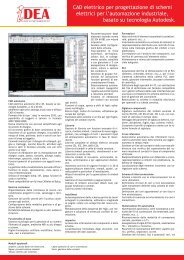
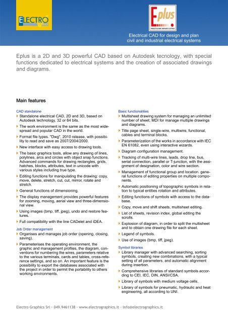
Electrical CAD for design and plan<br />
civil and industrial electrical systems<br />
Eplus is a 2D and 3D powerful CAD based on Autodesk tecnology, with special<br />
functions dedicated to electrical systems and the creation of associated drawings<br />
and diagrams.<br />
Main features<br />
CAD standalone<br />
Standalone electrical CAD, 2D and 3D, based on<br />
Autodesk technology, 32 or 64 bits.<br />
The work environment is the same as the most widespread<br />
and popular CAD in the world.<br />
Format file types. "Dwg", 2010 release, with possibility<br />
to read and save as 2007/2004/2000.<br />
New interface with easy access to drawing tools.<br />
The basic graphics tools, allow any drawing of lines,<br />
polylines, arcs and circles with object snap functions.<br />
Advanced commands for drawing rectangles, grids,<br />
hatches, blocks, attributes, text in unicode with<br />
various styles including true type.<br />
Editing functions for manipulating the drawing: copy,<br />
move, delete, stretch, cut, cut, mirror, rotate and<br />
stretch.<br />
General functions of dimensioning.<br />
The display management provides powerful features<br />
for zooming, moving, aerial view and three-dimensional<br />
view.<br />
Using images (bmp, tiff, jpeg), undo and restore features.<br />
Full compatibility with the line CADelet and iDEA.<br />
Job Order management<br />
Organises and manages job order (opening, closing,<br />
saving).<br />
Parameterises the operating environment, the<br />
graphic and management profiles, the diagram, conventions<br />
for numbering the wires, parameters relative<br />
to the various terminals, cards and tables, cross-reference<br />
settings, and so on. An important feature is the<br />
possibility to export the databases associated with<br />
the project in order to permit the portability to others<br />
working environments.<br />
Basic functionalities<br />
Multisheet drawing system for managing an unlimited<br />
number of sheet; MDI for manage multiple drawings<br />
and diagrams.<br />
Title page sheet, single-wire, multiwire, functional,<br />
cables and terminal blocks.<br />
Parameterization of the works in accordance with IEC<br />
EN 61082, even using interactive wizards.<br />
Diagram configuration management.<br />
Tracking of multi-wire lines, leads, drop line, bus,<br />
serial connection, parallel or T-junction, with the assignment<br />
of designation, color and wire section.<br />
Management of functional group and location. general<br />
functions of editing properties on multiple components.<br />
Automatic positioning of topographic symbols in relation<br />
to typical entities rotation and attributes.<br />
Editing functions of symbols with access to the database.<br />
Copy, move and shift sheets, multisheet editing.<br />
List of sheets, revision index, global editing the<br />
scrolls.<br />
Explosion of diagram, in order to split the multisheet<br />
and to obtain one drawing file for each sheet.<br />
Legend of symbols.<br />
Use of images (bmp, tiff, jpeg).<br />
Symbol libraries<br />
Library manager with advanced searching, sorting<br />
symbols, creating new combinations, with a typical<br />
setting of all parameters, and automatic alignment<br />
during insertion.<br />
Comprehensive libraries of standard symbols according<br />
to CEI, IEC, DIN, ANSI/CSA.<br />
Library of symbols with medium voltage cells.<br />
Library of symbols for pneumatic, hydraulic and heat<br />
engineering, all according to UNI.<br />
<strong>Electro</strong> <strong>Graphics</strong> Srl - 049.9461138 - www.electrographics.it - info@electrographics.it
Eplus - Electrical CAD for designing electrical systems<br />
Standard symbols for security, fire alarm, intrusion<br />
detection and domotic applications.<br />
Wide library of 2D and 3D shapes of electrical, cabinets,<br />
frames, ducts and installation details.<br />
Wizard interactive for the creation of user symbols.<br />
Management of macro-symbols and typical sheet.<br />
Using universal symbols (black box) for functional<br />
groups or boards.<br />
Unlimited user library.<br />
Inspector<br />
List of all components in the diagram and view of<br />
their properties.<br />
Rapid localization of elements and editing of associated<br />
data.<br />
Plant drawing<br />
Drawing of walls, doors and windows according to<br />
typical representations in 2D or 3D.<br />
Drawing of chimneys, niches, pilasters, pillars and<br />
columns.<br />
Automatic dimensioning the floorplan.<br />
Legend symbols with customizable descriptions.<br />
Definition of local and interactive link with the symbols<br />
contained within.<br />
Tables relating to defined local, utilities, installed<br />
power,...<br />
Labelling of the ducts and typological assignment of<br />
the layings according to IEC.<br />
Drawing from pre-computation<br />
Inserting symbols on the plan, relating to the items<br />
provided on the preliminary computation.<br />
Line check on the quantities already introduced and<br />
compared with expected quantities.<br />
Monitoring the amount of work in relation to the elements<br />
introduced in the drawing.<br />
Lighting calculation<br />
Lighting calculation according to UNI 12464, with<br />
definable and automatic layout of devices on the<br />
same floor plan.<br />
Representation of local 3D with ISOLUX on walls and<br />
horizontal surfaces. Verification of illumination, direct<br />
or with more reflections, on the walls.<br />
Extensive list of equipment, complete of the photometric<br />
characteristics, extensible by importing EULU-<br />
MDAT files.<br />
Report of calculation exportable to RTF files.<br />
Conduits definition<br />
Drawing conduits and three-dimensional rendering.<br />
Assign materials and the necessary accessories of<br />
the conduit.<br />
Exploration of the materials used.<br />
Table of sections and parts used.<br />
Automatic determination of the optimal path cables.<br />
Verification of the packaging of a conduit, in relation<br />
to the pipe or conduit chosen, with control of the conditions<br />
of removable from, required by the standard.<br />
Drawing details of the laying of cables in conduits.<br />
Units definition<br />
Definition of conduits or dorsal distribution in 3D with<br />
the allocation of data relating to units contained therein.<br />
Verification of consistency between laying of cables<br />
and conduit; management of multiple laid for the<br />
same user.<br />
Automatic detection of the length of each leg, the<br />
conditions of proximity and layng.<br />
Definition of distribution and allocation of loads and<br />
their electrical characteristics.<br />
Labelling of loads. Representation of the installation<br />
data. Table of cables.<br />
Identification of the method of installation provided,<br />
and summary table of standard references.<br />
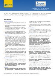
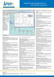
Bi-directional connection with the module Ampère<br />
(optional module, see Ampère line) for the network<br />
calculation.<br />
Automatic generation of multi-line, single-line or<br />
radial diagram after the project in Ampère.<br />
Export data to software for estimation Sigma (optional<br />
module, see Sigma (italian only)).<br />
Variations during construction<br />
Automatic processing of design variation, for comparison<br />
between states of the project.<br />
Extraction of data for the calculation of the variation,<br />
with elements added, removed or changed.<br />
Blocks diagram<br />
Management of the block diagram of the system.<br />
Automatic generation of the panels block diagram as<br />
a result of the dimensioning done in Ampère.<br />
Symbols marking<br />
Automatic symbols marking according to IEC750,<br />
IEC 61346, IEC 3-34, with consistency checks in real<br />
time.<br />
Setting of marking parameters (letter, function, location,<br />
sheet, row, column, index).<br />
Creation of user marking profiles.<br />
Cross reference<br />
Automatic generation of cross-references among<br />
assembled elements in the diagram and update in<br />
real time.<br />
Semi-automatic insertion of cross-reference labels.<br />
<strong>Electro</strong> <strong>Graphics</strong> Srl - 049.9461138 - www.electrographics.it - info@electrographics.it
Eplus - Electrical CAD for designing electrical systems<br />
Interconnection diagram<br />
Block diagram of the interconnections among the<br />
various locations.<br />
Definition of bundles of cables and their connection to<br />
the terminal blocks defined in (interconnection diagram).<br />
Definition of cables belonging to different bundles<br />
and their labeling.<br />
Check of consistency and orientation between cables<br />
and terminal blocks.<br />
Wire numbering<br />
Automatic (up to 10 sheets), semi-automatic or<br />
manual numbering of connection wires (incremental,<br />
positional, etc.).<br />
Managing references of wires on different sheets.<br />
Terminal boards and connectors<br />
Database of terminals and connectors with over 1800<br />
items from leading manufacturers.<br />
Definition of terminal blocks, with a choice of types<br />
and parameters setting.<br />
Inserting neutral terminals and their automatic assignment<br />
as result of analysis based on the interconnection<br />
diagram.<br />
Using multiple plans or special terminals (disconnectors,<br />
fuse, etc.).<br />
Automatic entry with rubber-band line or box and terminal<br />
numbering (in stages, start-ups, sequences,<br />
etc.).<br />
Managing junction box.<br />
Marking the terminal with the editing terminal numbering.<br />
Localization terminals and connectors with automatic<br />
navigator.<br />
Automatic reconstruction of bridges.<br />
Automatic generation and design of terminal blocks<br />
and connectors with representations definable.<br />
Automatic design of the connection cable as certified<br />
terminals and connectors.<br />
Tables of terminal blocks and cable routing tables<br />
after processing with Cablo.<br />
Layout panel<br />
Drawing guides and conduits, with calculation of the<br />
length.<br />
Semi-automatic arrangement of the shapes of the<br />
components, with filter functions for location or function,<br />
on the bottom plate, panel or doors.<br />
Automatic insertion of DIN guide.<br />
Automatic generation of drilling scheme, for panels.<br />
Automatic dimensioning and 3D representation.<br />
Thermal testing of panels (CEI 17-43)<br />
Calculation of the overtemperature in the cabinet<br />
according to CEI 17-43.<br />
Control on overcoming the working temperature of<br />
the components used.<br />
Stampe multifoglio e <strong>PDF</strong><br />
Automatic printing of sheets of the diagram.<br />
Exporting sheets as several image formats (bmp, tiff,<br />
jpeg, etc.).<br />
Creating a <strong>PDF</strong> file of the diagram, for a single<br />
project document.<br />
Translation<br />
Automatic translation of texts and descriptive elements<br />
of the diagram in more languages, activated<br />
at choice.<br />
Dictionaries, each one with several languages,<br />
provided by thousands of translated texts.<br />
Creation of custom dictionaries.<br />
Unicode text handling.<br />
List of the untranslated words in a temporarily dictionary<br />
for later translation.<br />
Use the dictionary as an archive of phrases to be<br />
included in the drawing.<br />
Database<br />
Access to the database with only one visualization<br />
tool, equipped with a powerful search and filtering<br />
according to the type of items to display.<br />
Managing databases in client / server.<br />
Editing and deployment of all archives, with automatic<br />
update from the Web<br />
Stock materials with over 55000 basic articles.<br />
Importing files in standard Metel ® provided by the<br />
manufacturers and distributors of electrical material.<br />
Database with over 5000 items of cost feature.<br />
Database with over 1500 standard formation (auxiliary<br />
and power contactors, relays, buttons, etc.).<br />
Database with over 3000 cables and 1300 types of<br />
ducts and pipes.<br />
Database with the electrical characteristics of more<br />
than 35000 devices (switches, fuses, breakers, etc.)<br />
and busbars.<br />
Materials table<br />
Summary Table of the materials used, with user-editable<br />
format.<br />
Bi-directional connection with the module Tabula<br />
(optional module, see Tabula), for the management of<br />
Bill of material.<br />
AutoSheet<br />
Wizard to create a multisheet diagram assembling<br />
drawings previously developed, with preview of the<br />
new project. Managing sheets sorting, components<br />
<strong>Electro</strong> <strong>Graphics</strong> Srl - 049.9461138 - www.electrographics.it - info@electrographics.it
Eplus - Electrical CAD for designing electrical systems<br />
marking with inconsistency checking and auto-correction.<br />
WebSheet<br />
Innovative tool to view and print the multisheet diagram<br />
using the Internet browser, without the application<br />
software installed.<br />
Distribution of the projects on the Web, in a compact<br />
in size and readable from any device, PC, Mac, or<br />
Tablet.<br />
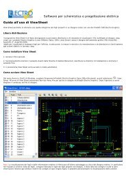
ViewSheet<br />
Viewer of multisheet diagrams with possibility to print<br />
(in <strong>PDF</strong>): This is a free tool to see the diagrams<br />
without requiring the software that created them.<br />
Integrations<br />
Tabula:Bill of materials<br />
Cablo: Management wiring lists and connection<br />
Ampère Professional: Calculation of electrical<br />
networks<br />
Vario: Management of variations in diagram<br />
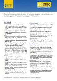
Solergo: Photovoltaic engineering<br />
System requirements<br />
Intel® Pentium® 4 or AMD Athlon® dual-core processor,<br />
3.0 GHz or higher with SSE2 technology.<br />
2GB RAM minimum.<br />
2 GB free disk space for installation.<br />
DVD drive.<br />
Video e scheda grafica a colori con risoluzione<br />
minima 1024x768.<br />
LPT port or USB port, mouse, printer or plotter.<br />
Windows XP, Vista o 7.<br />
<strong>Electro</strong> <strong>Graphics</strong> Srl - 049.9461138 - www.electrographics.it - info@electrographics.it