Einwandiges System - Montageanleitung - eka edelstahlkamine
Einwandiges System - Montageanleitung - eka edelstahlkamine
Einwandiges System - Montageanleitung - eka edelstahlkamine

You also want an ePaper? Increase the reach of your titles
YUMPU automatically turns print PDFs into web optimized ePapers that Google loves.
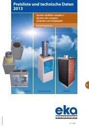
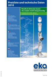
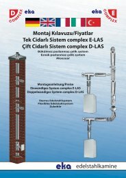
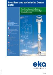
<strong>Einwandiges</strong> Schornsteinsystem<br />
<strong>eka</strong> complex E<br />
Wanddicke 0,6 mm<br />
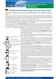
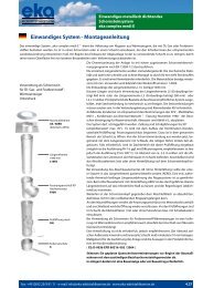
Assembly instructions for single wall system <strong>eka</strong> complex E<br />
The single wall stainless steel system <strong>eka</strong> complex E serves the derivation of exhaust gases from boilers which are operated by oil,<br />
natural, gas or solid fuels. It is to be inserted in a chimney or in a shaft which must correspond to the requirements of the national<br />
directions, f.e. EN 13384-1/2.<br />
Before starting the installation of the inliners the available chimney is to be cleaned.<br />
The single length elements are to be pulled apart. Mechanical stability and quick and safe assembly is guaranteed by the depth of<br />
the connecting sleeves of 80mm.<br />
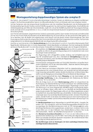
No locking band is necessary. The material thickness is at least 0.6 mm. The stiff elements are made from stainless steel with the<br />
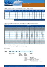
material numbers 1.4404 (AISI 316L). The installation length of the length element L 10 is 1000 mm. Shorter lengths are possible<br />
by use of the length elements L5 (installation length amounts to 460 mm)<br />
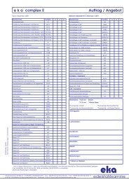
Use as a chimney<br />
or the length elements L3 (installation length amounts to 280 mm) or by<br />
for oil gas fuel and festival fuel -<br />
cutting the length element with two female couplers (Cut only with cutting<br />
Warm producer<br />
discs suitable for high-grade steel!) . In principle all components are suitable as<br />
Subpressure<br />
a wet chimney system.<br />
Condensate inside of the chimney is to be channeled away according to the<br />
terminal KIT<br />
regulations of the ATV - memorandum M 251 „condensates from condensing<br />
AE / AERO<br />
boilers“ in version November, 1998 .<br />
(Alternative terminal with rain The chimney may be obliquely led. Elbows to max. of 90 ° (better until 45°)are<br />
collar AEH2)<br />
allowed. Start construction by joining condensate collector with drain/inspection<br />
length/ T- element. In order to achieve this the mineral shaft is to be<br />
opened in the area concerned. Now from the top of the chimney beginning<br />
<br />
length 1080 mm<br />
down by rope. If necessary a upper inspection length is inserted in the roof<br />
with wall distancer<br />
area (it is possible to implement PH 14, if necessary with diffusion barrier,<br />
LAHKS<br />
recommended here is, nevertheless, the implementation P, proof up to<br />
200 ° C). Every approx. 2-3 m lengths with wall distancer should be mounted<br />
in order to center the pipe in the shaft. Finally the terminal kit (with or<br />
without ventilation) is to be fastened on the chimney`s top.<br />
ting<br />
inside the length element (AERO). Provisions for a possible thermally<br />
induced length expansion of the chimney are to be taken. By using the terminal<br />
kit with ventilation AEH2 the freestanding uppermost length element<br />
is to be cut to the necessary measure and the rain collar is to be mounted .<br />
Furthermore the chimney head is to be sealed along with the terminal kit in<br />
length<br />
such a way that rain cannot penetrate into the remaining ring gap.<br />
1080 mm<br />
L10KS<br />
The T- element is to be covered at the opening of the mineral shaft to the<br />
connecting pipe with mineral wool wraps and afterwards the opening is closed<br />
again. In front of the inspection lengths to be inserted into the mineral<br />
shaft stainless steel doors are to be mounted (with or without shaft).<br />
By using as a chimney for solid fuel - boilers – (operating mode negative<br />
pressure) it is recommended to insulate the lengths elements with insulating<br />
pipes. Ventilation is not necessary. It is recommended to insert no smaller diameters<br />
than 150 mm (soot depositions). The distance between the outside<br />
T90° high temperature<br />
of the inliner and the inside of the chimney / shaft must amount to at least<br />
F90H<br />
10 mm.<br />
When using a chimney for oil - and gas boilers - (operating mode negative<br />
Inspection length 120/140 mm pressure) an isolation of the exhaust gas management for temperature reasons<br />
is not necessary. Nevertheless, it is recommended to use an isolation of<br />
for high temperature PH14<br />
the inliner for the decrease of noises . Ventilation is not necessary, it is , however,<br />
recommended. The distance between the outside of the inliner and the<br />
stainless door with<br />
adjustable shaft 200 mm<br />
SES14<br />
inside of the chimney / shaft must amount to at least 10 mm.<br />
Authoritative for the implementation of the facility are the statements made<br />
condensate collector<br />
in the product information section of the “Declaration of Conformity”:<br />
with drain<br />
CE: D-00 36 CPD 90216 002/2004<br />
K<br />
The facility is to be declared before the start of construction work with the<br />
responsible district master chimney sweeper.<br />
2.40<br />
<strong>eka</strong>-<strong>edelstahlkamine</strong> · robert-bosch-straße 4 · D-95369 untersteinach · tel: +49 (0)92 25/9 81 01