PubTeX output 2002.07.17:1332
PubTeX output 2002.07.17:1332
PubTeX output 2002.07.17:1332

You also want an ePaper? Increase the reach of your titles
YUMPU automatically turns print PDFs into web optimized ePapers that Google loves.
Freightliner SmartShift Troubleshooting 26-23<br />
FLA COE<br />
FLB COE<br />
FLD Conventional<br />
Business Class<br />
Business Class M2<br />
FLC 112 Conventional<br />
> Century Class Conventional<br />
> Argosy COE<br />
Cargo<br />
> Columbia<br />
Condor<br />
Freightliner<br />
Service Bulletin<br />
General Information<br />
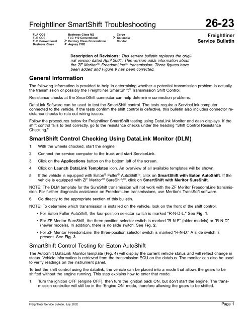
Description of Revisions: This service bulletin replaces the original<br />
version dated April 2001. This version adds information about<br />
the ZF Meritor TM FreedomLine TM transmission. Three figures have<br />
been added and Figure 9 has been corrected.<br />
The following information is provided to help in determining whether a potential transmission problem is actually<br />
the transmission or possibly the Freightliner SmartShift ® Transmission Shift Control.<br />
Resistance checks at the SmartShift connector can help determine connection problems.<br />
DataLink Software can be used to test the SmartShift control. The tests require a ServiceLink computer<br />
connected to the vehicle. If the tests confirm the shift control is defective, this bulletin also includes connector resistance<br />
checks to rule out wiring issues.<br />
Follow the procedures below for Freightliner SmartShift testing using DataLink Monitor and dash displays. If the<br />
shift control fails to test correctly, go to the resistance checks under the heading "Shift Control Resistance<br />
Checking."<br />
SmartShift Control Checking Using DataLink Monitor (DLM)<br />
1. With the wheels chocked, start the engine.<br />
2. Connect the service computer to the truck and start ServiceLink.<br />
3. Click on the Applications button on the bottom left of the screen.<br />
4. Click on Launch DataLink Templates icon. An overview of all available templates will be shown.<br />
5. If the vehicle is equipped with Eaton ® Fuller ® AutoShift TM , click on SmartShift with Eaton AutoShift. If the<br />
vehicle is equipped with ZF Meritor TM SureShift TM , click on SmartShift with Meritor SureShift.<br />
NOTE: The DLM template for the SureShift transmission will not work with the ZF Meritor FreedomLine transmission.<br />
For further diagnostic assistance on FreedomLine transmissions, use Meritor’s TransSoft software.<br />
6. Go directly to the appropriate section of this bulletin.<br />
NOTE: To determine which transmission is installed on the vehicle, look on the front of the shift control.<br />
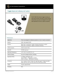
• For Eaton Fuller AutoShift, the four-position selector switch is marked "R-N-D-L." See Fig. 1.<br />
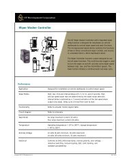
• For ZF Meritor SureShift, the three-position selector switch is marked "R-N-F" (older models) or "R-N-D"<br />
(newer models). In addition, there is no slide switch. See Fig. 2.<br />
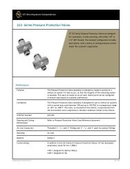
• For ZF Meritor FreedomLine, the three-position selector switch is marked "R-N-D." A slide switch is<br />
present. See Fig. 3.<br />
SmartShift Control Testing for Eaton AutoShift<br />
The AutoShift DataLink Monitor template (Fig. 4) will display the current vehicle status and will reflect change in<br />
status. Vehicle information is retrieved from the transmission ECU on the databus. The monitor can also be used<br />
to verify readings on the instrument panel.<br />
To test the shift control using the datalink, the vehicle can be placed into a mode that allows the gears to be<br />
shifted without the engine running. This step explains how to enter that mode.<br />
1. Turn the ignition OFF (engine OFF), then turn the ignition back ON, but don’t start the engine. The transmission<br />
controller will still be in the ’Engine ON’ mode, therefore allowing the gears to be shifted.<br />
Freightliner Service Bulletin, July 2002 Page 1
26-23 Freightliner SmartShift Troubleshooting<br />
Freightliner<br />
Service Bulletin<br />
FLA COE<br />
FLB COE<br />
FLD Conventional<br />
Business Class<br />
Business Class M2<br />
FLC 112 Conventional<br />
> Century Class Conventional<br />
> Argosy COE<br />
Cargo<br />
> Columbia<br />
Condor<br />
3<br />
4<br />
5<br />
6<br />
7<br />
2<br />
3<br />
4<br />
SHIFT<br />
UP<br />
1<br />
2<br />
9<br />
8<br />
1<br />
Smart<br />
Shift<br />
PULL<br />
PUSH<br />
SHIFT<br />
DOWN<br />
6<br />
5<br />
11/23/99<br />
1. SmartShift Control<br />
2. Slide Switch (forward driving mode switch)<br />
3. MAN Position (on slide switch)<br />
4. AUTO Position (on slide switch)<br />
5. Upshift Direction<br />
6. Reverse Position (on selector switch)<br />
7. Selector Switch<br />
8. Neutral Position (on selector switch)<br />
9. Drive Position (on selector switch)<br />
10. Low Position (on selector switch)<br />
11. Downshift Direction<br />
10 11<br />
f270082<br />
Fig. 1, SmartShift Control (with Eaton Fuller AutoShift)<br />
11/23/99<br />
f270081<br />
NOTE: Newer SureShift models have a "D" (for drive) in<br />
place of the "F" (for forward).<br />
1. SmartShift Control<br />
2. Upshift Direction<br />
3. Reverse Position (on selector switch)<br />
4. Selector Switch<br />
5. Neutral Position (on selector switch)<br />
6. Forward Position (on selector switch)<br />
7. Downshift Direction<br />
Fig. 2, SmartShift Control (with ZF Meritor<br />
SureShift)<br />
7<br />
5<br />
6<br />
3<br />
4<br />
7<br />
1<br />
2<br />
9<br />
8<br />
03/21/2002<br />
1. SmartShift Control<br />
2. Slide Switch (forward driving mode switch)<br />
3. MAN Position (on slide switch)<br />
4. AUTO Position (on slide switch)<br />
5. Upshift Direction<br />
6. Reverse Position (on selector switch)<br />
7. Selector Switch<br />
8. Neutral Position (on selector switch)<br />
9. Drive Position (on selector switch)<br />
10. Downshift Direction<br />
10<br />
f270080<br />
Fig. 3, SmartShift Control (with ZF Meritor FreedomLine)<br />
2. Test the operation of the shift control for Reverse (R) and Neutral (N).<br />
Page 2<br />
Freightliner Service Bulletin, July 2002
Freightliner SmartShift Troubleshooting 26-23<br />
FLA COE<br />
FLB COE<br />
FLD Conventional<br />
Business Class<br />
Business Class M2<br />
FLC 112 Conventional<br />
> Century Class Conventional<br />
> Argosy COE<br />
Cargo<br />
> Columbia<br />
Condor<br />
Freightliner<br />
Service Bulletin<br />
DataLink Monitor<br />
ECU<br />
Software<br />
Version:<br />
Range<br />
Selected<br />
(Lever):<br />
Gear<br />
Attained<br />
(Trans.):<br />
Battery Voltage<br />
Gear Actuator<br />
Up−Shift Req.<br />
Ign. Switch<br />
Shaft Speeds [rpm]<br />
Input Main Output<br />
OFF<br />
OFF<br />
Switched Batt. (Ign.)<br />
3000<br />
Rail Actuator<br />
Down−Shift Req.<br />
Ign. Interrupted<br />
2500<br />
2000<br />
1500<br />
1000<br />
OFF OFF<br />
Shift Finger Rail Position<br />
0<br />
0 25 50 75<br />
100<br />
Shift Finger Gear Position<br />
0<br />
0 25 50 75<br />
100<br />
500<br />
0<br />
0 0 0<br />
FAULTS<br />
MID PID/SID FMI SID STATUS OCC CNT<br />
Version 1.1, January 2000<br />
02/19/2001 f610457<br />
Fig. 4, DataLink Monitor Template for Eaton Fuller AutoShift<br />
2.1 Select R (Reverse) on the selector switch. In the Range Selected field of the template an ’R’ should<br />
be displayed.<br />
2.2 Select N (Neutral) on the selector switch. In the Range Selected field of the template an ’N’ should<br />
be displayed.<br />
3. Test the operation of the shift control for Drive (D).<br />
3.1 Select D (Drive) on the selector switch and turn the slide switch (reading "Automatic/Manual") to Automatic.<br />
In the Range Selected field of the template, a ’D’ should be displayed for Drive.<br />
3.2 With the selector switch still on D (Drive), toggle the slide switch from Automatic to Manual and<br />
back. Confirm that the Range Selected field shows a ’D’ while in Automatic and an ’H’ (High) while<br />
in Manual.<br />
3.3 While in Manual mode, change the selector switch to L (Low) and confirm that the Range Selected<br />
field changes from ’H’ to ’L.’<br />
4. Test upshifting and downshifting.<br />
Freightliner Service Bulletin, July 2002 Page 3
26-23 Freightliner SmartShift Troubleshooting<br />
Freightliner<br />
Service Bulletin<br />
FLA COE<br />
FLB COE<br />
FLD Conventional<br />
Business Class<br />
Business Class M2<br />
FLC 112 Conventional<br />
> Century Class Conventional<br />
> Argosy COE<br />
Cargo<br />
> Columbia<br />
Condor<br />
4.1 With the selector switch on D (Drive), pull and hold the shift control lever. The Up-Shift Req. field will<br />
turn green and read ’ON’ for 3 seconds.<br />
4.2 Push and hold the shift control lever. The Down-Shift Req. field will turn green and read ’ON’ for 3<br />
seconds.<br />
NOTE: A blinking display indicates that the transmission is attempting to shift into the gear position. A solid display<br />
shows the current gear position attained.<br />
5. When the selector switch is in any position but N (Neutral), the Ign. Interrupt field on the Monitor template<br />
will read ’YES.’<br />
SmartShift Control Testing for ZF Meritor SureShift and FreedomLine<br />
The SmartShift control test for a ZF Meritor SureShift system can be performed by using the dash-mounted gear<br />
display. The SureShift DataLink Monitor (DLM) template can be used if further testing of the system is necessary,<br />
for example, to confirm dash display readings or gear positions. See Fig. 5.<br />
NOTE: The DLM template for the SureShift transmission will not work with the FreedomLine transmission. For<br />
further diagnostic assistance on FreedomLine transmissions, use Meritor’s TransSoft software.<br />
WARNING<br />
For SureShift transmissions, do not depress the clutch pedal during these tests. Doing so could result in<br />
the vehicle moving, possibly causing vehicle damage or personal injury.<br />
Make sure all tires are chocked and the parking brake is set before performing the following tests. These<br />
tests require the vehicle to be started and precautions need to be taken to ensure the vehicle will not<br />
move.<br />
1. Test the operation of the shift control for Reverse (R) and Neutral (N).<br />
1.1 Move the selector switch to R (Reverse). Confirm that the display is changing from ’N’ to ’RL’ (Reverse<br />
Low), the default reverse gear. The display will change to ’CL’ (Clutch) after one second.<br />
Please repeat this step if the reading disappeared quickly.<br />
1.2 Pull the shift control lever once to upshift to High Reverse. Confirm the display changes to ’RH’ (Reverse<br />
High).<br />
2. Test the operation of the shift control for Forward (F) or Drive (D).<br />
2.1 Move the selector switch to F (Forward) or Drive (D).<br />
2.2 Test upshifting and downshifting. Push, then pull, the shift control lever through all the gears and verify<br />
that each gear displays correctly on the dash display.<br />
If the display or the DLM template does not confirm the SmartShift control position, the shift control should be<br />
tested.<br />
Shift Control Resistance Checking<br />
1. Shut down the engine, apply the parking brake, and chock the tires.<br />
2. Remove the steering column trim panels. See Fig. 6.<br />
2.1 Remove the screws securing the panels.<br />
2.2 Separate the forward and rear panels to access the shift control.<br />
Page 4<br />
Freightliner Service Bulletin, July 2002
Freightliner SmartShift Troubleshooting 26-23<br />
FLA COE<br />
FLB COE<br />
FLD Conventional<br />
Business Class<br />
Business Class M2<br />
FLC 112 Conventional<br />
> Century Class Conventional<br />
> Argosy COE<br />
Cargo<br />
> Columbia<br />
Condor<br />
Freightliner<br />
Service Bulletin<br />
DataLink Monitor<br />
Model<br />
s/n<br />
Range<br />
Low<br />
Gear Position<br />
100<br />
75<br />
Trans Shaft Speeds [rpm]<br />
Input<br />
Output<br />
Software<br />
Gear Selected<br />
50<br />
3000<br />
2500<br />
2000<br />
Gear Attained<br />
25<br />
0<br />
0<br />
1500<br />
1000<br />
Rail Position<br />
500<br />
0<br />
0 0<br />
0<br />
0<br />
25<br />
50<br />
75<br />
100<br />
FAULTS<br />
MID PID/SID FMI SID STATUS OCC CNT<br />
Trans ECU Voltage<br />
Version 1.2, February 2001<br />
01/11/2001 f610466<br />
Fig. 5, DataLink Monitor Template for ZF Meritor SureShift<br />
3. Disconnect the electrical connector from the plug on the shift control unit. See Fig. 7.<br />
4. Assemble the wire extension from the parts in Table 1 to allow for easy resistance testing.<br />
Parts for Wire Extension<br />
Part Number Description Qty.<br />
PAC12110847 Metri-Pack Terminal 3<br />
PAC12047767 Connector Terminal 3<br />
48-2493-184 18GA GTX Wire, Yellow 3ftx3<br />
PAC12047781 3-Pin Connector 1<br />
PAC12047783 Connector Lock 1<br />
Table 1, Parts for Wire Extension<br />
Freightliner Service Bulletin, July 2002 Page 5
26-23 Freightliner SmartShift Troubleshooting<br />
Freightliner<br />
Service Bulletin<br />
FLA COE<br />
FLB COE<br />
FLD Conventional<br />
Business Class<br />
Business Class M2<br />
FLC 112 Conventional<br />
> Century Class Conventional<br />
> Argosy COE<br />
Cargo<br />
> Columbia<br />
Condor<br />
5<br />
2<br />
1<br />
2<br />
3<br />
4<br />
07/23/99 f270066<br />
1<br />
07/23/99 f270067<br />
1. Steering Column Panel Capscrews<br />
2. Shift Control<br />
1. Steering Wheel<br />
2. Shift Control Bracket<br />
3. Fasteners<br />
4. Electrical Connector<br />
5. Shift Control<br />
Fig. 7, SmartShift Components<br />
Fig. 6, Steering Column Panel<br />
4.1 Crimp the connector terminals at the end of each 3-foot (1-meter) wire.<br />
4.2 Assemble the 3-pin connector with the connector terminals and connector lock.<br />
4.3 Crimp the Metri-Pak terminals on the other end of the wires.<br />
5. Plug the wire extension into the plug on the shift control unit. See Fig. 8 for SmartShift terminal positions.<br />
NOTE: Using this new wire extension prevents the need to remove the shift control.<br />
6. Check the resistance at the other end of the wires. See Fig. 9.<br />
• Use Table 2 for a three-position control (R-N-F or R-N-D).<br />
• Use Table 3 and Table 4 for a four-position (R-N-D-L) control.<br />
Parts<br />
Parts are available through the PDCs.<br />
Warranty<br />
This is an informational bulletin only; warranty does not apply.<br />
Page 6<br />
Freightliner Service Bulletin, July 2002
Freightliner SmartShift Troubleshooting 26-23<br />
FLA COE<br />
FLB COE<br />
FLD Conventional<br />
Business Class<br />
Business Class M2<br />
FLC 112 Conventional<br />
> Century Class Conventional<br />
> Argosy COE<br />
Cargo<br />
> Columbia<br />
Condor<br />
Freightliner<br />
Service Bulletin<br />
1<br />
D3<br />
D2<br />
D1<br />
A<br />
08/10/2000 f261085<br />
Fig. 8, SmartShift Terminal Positions<br />
2<br />
3<br />
05/16/2002 f270075<br />
A. Plug the newly assembled wire extension into the<br />
plug on the shift control unit.<br />
1. Shift Control Unit<br />
2. Digital Multimeter (set to ohms)<br />
3. Metri-Pak Terminals (at wire ends)<br />
Fig. 9, Resistance Checking at Shift Control<br />
Check Resistance on the Three-Position Control at D1 and D3<br />
Selector Switch + Lever Position<br />
Reading (kOhm)<br />
R 10.2 - 10.6<br />
N 1.65 - 1.71<br />
ForD 2.65 - 2.75<br />
R+Up 4.14 - 4.3<br />
R + Down 6.07 - 6.31<br />
Table 2, Check Resistance on the Three-Position Control at D1 and D3<br />
Freightliner Service Bulletin, July 2002 Page 7
26-23 Freightliner SmartShift Troubleshooting<br />
Freightliner<br />
Service Bulletin<br />
FLA COE<br />
FLB COE<br />
FLD Conventional<br />
Business Class<br />
Business Class M2<br />
FLC 112 Conventional<br />
> Century Class Conventional<br />
> Argosy COE<br />
Cargo<br />
> Columbia<br />
Condor<br />
Check Resistance on the Four-Position Control at D2 and D3<br />
Selector Switch Position<br />
Reading (kOhm)<br />
R 2.947 - 3.067<br />
N 0.347 - 0.361<br />
D 0.606 - 0.630<br />
L 1.65 - 1.72<br />
Table 3, Check Resistance on the Four-Position Control at D2 and D3<br />
Check Resistance on the Four-Position Control at D1 and D3<br />
Slide Switch + Lever Position<br />
Reading (kOhm)<br />
Manual 2.865 - 2.981<br />
Manual + Up 0.531 - 0.553<br />
Manual + Down 1.150 - 1.197<br />
Auto 11.27 - 11.73<br />
Table 4, Check Resistance on the Four-Position Control at D1 and D3<br />
Page 8<br />
Freightliner Service Bulletin, July 2002