Omnidirectional Vision for an Autonomous Helicopter - University of ...
Omnidirectional Vision for an Autonomous Helicopter - University of ...
Omnidirectional Vision for an Autonomous Helicopter - University of ...

You also want an ePaper? Increase the reach of your titles
YUMPU automatically turns print PDFs into web optimized ePapers that Google loves.
3.3 Feature Recognition Using Hu’s Moments<br />
As discussed in [22], Hu’s moments c<strong>an</strong> be used <strong>for</strong> feature<br />
recognition. Once the system has been trained on a certain<br />
feature, this feature c<strong>an</strong> be recognized regardless <strong>of</strong> its<br />
orientation, scaling or tr<strong>an</strong>slation. Although this technique<br />
is not invari<strong>an</strong>t to skewing, it was found that the feature<br />
(the letter H) could still be detected when it was skewed<br />
to 45 degrees horizontally, <strong>an</strong>d 30 degrees vertically. This<br />
technique was previously used successfully <strong>for</strong> detecting<br />
the same feature painted on a helipad during autonomous<br />
vision based l<strong>an</strong>ding [13].<br />
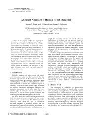
result is that the robot moves towards the centroid <strong>of</strong> targets.<br />
Omax<br />
Robot<br />
Centroid<br />
Omin<br />
Percieved area <strong>of</strong> target<br />
Average area <strong>of</strong> targets<br />
Omax<br />
Omin<br />
4 Centroid Finding Algorithm<br />
Step 1<br />
Step 2<br />
In order to find the centroid <strong>of</strong> the visual targets, it is<br />
necessary to know the relative dist<strong>an</strong>ce to each target. Since<br />
the targets were made to be the same size, the area <strong>of</strong> each<br />
target in the image is used as <strong>an</strong> indication <strong>of</strong> the dist<strong>an</strong>ce<br />
to the target. The algorithm runs as follows:<br />
For each image:<br />
find the area <strong>an</strong>d position <strong>of</strong> each detected target (x position<br />
only, since the task is in 2D.<br />
(A 1, A 2, A 3, ...A n; X 1, X 2, X 3, ...X n)<br />
Calculate the average, maximum <strong>an</strong>d minimum areas<br />
<strong>of</strong> the targets <strong>an</strong>d the positions <strong>of</strong> largest <strong>an</strong>d smallest<br />
targets:(A ave, A max, A min), (X max, X min).<br />
while(A max - A min ≥ threshold)<br />
Calculate the <strong>of</strong>fsets from the average area to the minimum <strong>an</strong>d<br />
the maximum areas:<br />
O max = A max - A ave<br />
O min = A ave - A min<br />
determine the action to take:<br />
if O max ≥ O min<br />
move away from X max<br />
else<br />
move towards X min<br />
loop<br />
This causes the robot to move away from the closest target<br />
or move towards the farthest target, until all the targets<br />
are roughly at the same dist<strong>an</strong>ce (within threshold). A useful<br />
property <strong>of</strong> this technique is that it is not necessary to<br />
know the actual dist<strong>an</strong>ce to each target, only the relative<br />
dist<strong>an</strong>ces.<br />
Figure 8 illustrates this algorithm. Note that the size<br />
<strong>of</strong> the solid-line circles represents the relative size <strong>of</strong> the<br />
targets as seen by the robot, while the dotted-line circles<br />
represent the average size <strong>of</strong> the targets. In Step 1, O min is<br />
greater th<strong>an</strong> O max , so the robot moves towards the farthest<br />
target. By Step 2, O max becomes larger th<strong>an</strong> O min , <strong>an</strong>d<br />
the robot moves away from the closest target. The overall<br />
Figure 8: Centroid Finding Algorithm<br />
5 Experimental Setup<br />
Although the omnidirectional vision system had been<br />
developed <strong>for</strong> use on <strong>an</strong> autonomous helicopter, it was decided<br />
that the system should first be tested on a ground<br />
robot. This would help to eliminate m<strong>an</strong>y problems be<strong>for</strong>e<br />
using the system on the helicopter, as it is easier to<br />
conduct experiments <strong>an</strong>d debug the code on a ground vehicle<br />
th<strong>an</strong> a helicopter. Experiments were thus first done<br />
on the Pioneer robot, <strong>an</strong>d once the robot could complete<br />
the centroid finding task consistently, the experiment was<br />
conducted on the helicopter. Although autonomous flight<br />
was not yet possible with our new helicopter plat<strong>for</strong>m, data<br />
could be collected from all the onboard sensors. The helicopter<br />
was flown under pilot control in the vicinity <strong>of</strong> the<br />
visual targets while the centroid finding algorithm was run.<br />
The GPS coordinates <strong>an</strong>d heading <strong>of</strong> the helicopter were<br />
logged as well as the comm<strong>an</strong>ds that were being generated<br />
by the algorithm. After the test flights the data were <strong>an</strong>alyzed<br />
to see if appropriate control comm<strong>an</strong>ds were being<br />
generated by the algorithm (the GPS coordinate <strong>of</strong> the centroid<br />
had been recorded, <strong>an</strong>d the helicopter’s heading <strong>an</strong>d<br />
location were compared to this).<br />
For the Pioneer-based experiment, a 23x17cm white H<br />
on a black background was used as the visual target. This<br />
version <strong>of</strong> the experiment was designed to be a scaleddown<br />
version <strong>of</strong> the outdoor one - since the targets would<br />
be much closer to the Pioneer, their size was reduced accordingly<br />
. The scale <strong>of</strong> the outdoor experiment (i.e. the<br />
maximum dist<strong>an</strong>ce that the targets could be from the helicopter<br />
<strong>for</strong> effective recognition) was determined by the<br />
resolution <strong>of</strong> the camera <strong>an</strong>d size that the outdoor targets<br />
could be made (83x70cm). For the outdoor experiment, the<br />
targets were placed on the circumference <strong>of</strong> a circle with a<br />
diameter <strong>of</strong> 12.2m. For the indoor experiment, the diameter<br />
was reduced to 2.5m.