Omnidirectional Vision for an Autonomous Helicopter - University of ...
Omnidirectional Vision for an Autonomous Helicopter - University of ...
Omnidirectional Vision for an Autonomous Helicopter - University of ...

You also want an ePaper? Increase the reach of your titles
YUMPU automatically turns print PDFs into web optimized ePapers that Google loves.
<strong>Omnidirectional</strong> <strong>Vision</strong> <strong>for</strong> <strong>an</strong> <strong>Autonomous</strong> <strong>Helicopter</strong><br />
Stef<strong>an</strong> Hrabar <strong>an</strong>d Gaurav S. Sukhatme<br />
Robotic Embedded Systems Laboratory<br />
Center <strong>for</strong> Robotics <strong>an</strong>d Embedded Systems<br />
Department <strong>of</strong> Computer Science<br />
<strong>University</strong> <strong>of</strong> Southern Cali<strong>for</strong>nia<br />
Los Angeles, Cali<strong>for</strong>nia, USA<br />
shrabar@robotics.usc.edu, gaurav@robotics.usc.edu<br />
Abstract<br />
We present the design <strong>an</strong>d implementation <strong>of</strong> <strong>an</strong> omnidirectional<br />
vision system used <strong>for</strong> sideways-looking sensing<br />
on <strong>an</strong> autonomous helicopter. To demonstrate the capabilities<br />
<strong>of</strong> the system, a visual servoing task was designed<br />
which required the helicopter to locate <strong>an</strong>d move towards<br />
the centroid <strong>of</strong> a number <strong>of</strong> visual targets. Results are presented<br />
showing that the task was successfully completed<br />
by a Pioneer ground robot equipped with the same omnidirectional<br />
vision system, <strong>an</strong>d preliminary test flight results<br />
show that the system c<strong>an</strong> generate appropriate control<br />
comm<strong>an</strong>ds <strong>for</strong> the helicopter.<br />
1 Introduction<br />
The m<strong>an</strong>euverability <strong>of</strong> helicopters makes them particularly<br />
useful aerial vehicles <strong>for</strong> a number <strong>of</strong> tasks, especially<br />
where take<strong>of</strong>f <strong>an</strong>d l<strong>an</strong>ding space is limited, or where<br />
steady flight at low speed is needed. The size <strong>an</strong>d high<br />
cost <strong>of</strong> operating helicopters do however limit their use <strong>for</strong><br />
such tasks. Smaller scale autonomous helicopters could <strong>of</strong>fer<br />
a viable alternative to their full scale versions <strong>for</strong> use<br />
in m<strong>an</strong>y tasks, such as aerial surveill<strong>an</strong>ce <strong>an</strong>d communications<br />
bridging.<br />
In order <strong>for</strong> such <strong>an</strong> unm<strong>an</strong>ned aerial vehicle (UAV) to<br />
navigate safely through <strong>an</strong> environment with tall obstacles,<br />
or to monitor features that are in the same horizontal pl<strong>an</strong>e<br />
as itself, the UAV must be equipped with sideways-looking<br />
sensors <strong>of</strong> some sort. Laser r<strong>an</strong>ge finders provide accurate<br />
r<strong>an</strong>ge in<strong>for</strong>mation <strong>an</strong>d have been used <strong>for</strong> obstacle avoid<strong>an</strong>ce<br />
<strong>an</strong>d 3D scene reconstruction [1, 2]. Commercially<br />
available laser altimeters are however limited to sc<strong>an</strong>ning<br />
in 2D, are prohibitively heavy <strong>an</strong>d power hungry. <strong>Vision</strong><br />
has been used successfully in m<strong>an</strong>y feature tracking [3] <strong>an</strong>d<br />
navigation tasks, <strong>an</strong>d is particularly useful because <strong>of</strong> the<br />
richness in in<strong>for</strong>mation that is received. Since CCD cameras<br />
are passive sensors, they typically draw little current,<br />
<strong>an</strong>d are light <strong>an</strong>d compactly packaged. St<strong>an</strong>dard lenses,<br />
however, have a limited field <strong>of</strong> view, so in order to sense a<br />
large area, the camera needs to be actuated. This gives only<br />
partial in<strong>for</strong>mation about the the scene at <strong>an</strong>y point in time,<br />
<strong>an</strong>d so scene stitching techniques are needed.<br />
An omnidirectional lens c<strong>an</strong> be used to give a 360 degree<br />
semi-spherical field <strong>of</strong> view [4], enabling the vision system<br />
to track features in the scene without actuating the camera.<br />
Also, multiple features in different parts <strong>of</strong> the scene<br />
c<strong>an</strong> be tracked simult<strong>an</strong>eously [5]. The properties <strong>of</strong> <strong>an</strong><br />
omnidirectional lens are well suited to the movement characteristics<br />
<strong>of</strong> a helicopter. A helicopter c<strong>an</strong> (essentially)<br />
inst<strong>an</strong>t<strong>an</strong>eously move in <strong>an</strong>y direction in 3D space, <strong>an</strong>d the<br />
lens allows it to ”see” in the direction it is moving, without<br />
having to p<strong>an</strong>/tilt the camera in that direction first.<br />
<strong>Omnidirectional</strong> vision has been used in m<strong>an</strong>y visionbased<br />
tasks [6] such as feature tracking [7], surveill<strong>an</strong>ce<br />
[8], navigation [9], 3D scene reconstruction [10, 11],<br />
visual servoing [7], <strong>an</strong>d localization [12]. <strong>Vision</strong>-based<br />
control <strong>of</strong> <strong>an</strong> autonomous helicopter has been done using<br />
a downwards looking camera with a st<strong>an</strong>dard lens[13,<br />
14, 15], <strong>an</strong>d omnidirectional cameras have been used on<br />
ground based robots [7, 9] but very little or no work on<br />
vision-based control <strong>of</strong> a helicopter using <strong>an</strong> omnidirectional<br />
lens has been done be<strong>for</strong>e.<br />
A UAV with omnidirectional sensing capabilities could<br />
be used <strong>for</strong> various applications. One class <strong>of</strong> tasks that<br />
it could be used <strong>for</strong> is locating the centroid <strong>of</strong> a number<br />
<strong>of</strong> features in 3D space, <strong>an</strong>d maintaining position at this<br />
centroid. For example, to simult<strong>an</strong>eously monitor a number<br />
<strong>of</strong> features, the optimal position <strong>for</strong> monitoring is likely to<br />
be at their centroid. If the UAV is acting as a hub, this could<br />
be a good position to facilitate communications.
2 <strong>Omnidirectional</strong> <strong>Vision</strong> System<br />
Our image capture system is comprised <strong>of</strong> a Net<strong>Vision</strong>360<br />
omnidirectional lens by Remote Reality, coupled<br />
to a Sony XC-55 black <strong>an</strong>d white CCD camera. The lens<br />
has a field <strong>of</strong> view <strong>of</strong> 360 degrees in the horizontal, <strong>an</strong>d<br />
from 35 to 92.5 degrees in the vertical pl<strong>an</strong>e. This gives a<br />
semi-spherical field <strong>of</strong> view, from the horizon down to 35<br />
degrees (if the camera is mounted with the lens pointing<br />
downwards). Since the system was designed <strong>for</strong> sideways<br />
looking sensing, the blind spot from 0-35 degrees was considered<br />
acceptable. A wireless video tr<strong>an</strong>smitter is used to<br />
tr<strong>an</strong>smit the video signal to a PC equipped with a frame<br />
grabber, which captures frames at 640x480 resolution.<br />
This introduced tr<strong>an</strong>smission noise into the signal, which<br />
hampered the feature detection. In the future, the Linux<br />
stack will be upgraded to h<strong>an</strong>dle the vision code, <strong>an</strong>d running<br />
this onboard will eliminate the tr<strong>an</strong>smission noise.<br />
Initially the CCD camera was mounted rigidly to the<br />
l<strong>an</strong>ding gear <strong>of</strong> the helicopter, but it was found that the<br />
high-frequency vibrations from the gas engine caused motion<br />
blur in the image. To reduce the vibrations tr<strong>an</strong>smitted<br />
to the camera, a mount was designed that decoupled the<br />
camera from the l<strong>an</strong>ding gear.<br />
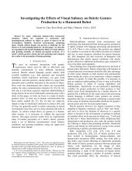
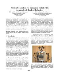
2.1 <strong>Helicopter</strong> Plat<strong>for</strong>m<br />
Our experimental test-bed AVATAR (<strong>Autonomous</strong> Vehicle<br />
Aerial Tracking And Reconnaiss<strong>an</strong>ce) [16] is a gaspowered<br />
radio-controlled model helicopter built from a<br />
Bergen chassis. The helicopter carries onboard processing<br />
power <strong>an</strong>d sensors in the <strong>for</strong>m <strong>of</strong> two PC104 stacks<br />
(one running Linux <strong>an</strong>d one running QNX), a Novatel RT-<br />
2 DGPS board, a compass, <strong>an</strong> Crossbow VGX IMU, a laser<br />
altimeter <strong>an</strong>d a CCD camera with the omnidirectional lens.<br />
The Linux stack consists <strong>of</strong> a Pentium II 233MHz processor<br />
<strong>an</strong>d <strong>an</strong> Imagination PX610a frame grabber. This stack<br />
will is used <strong>for</strong> image capturing <strong>an</strong>d running vision code.<br />
The QNX stack includes a Pentium III 700MHz processor<br />
<strong>an</strong>d is used <strong>for</strong> running the low-level helicopter control<br />
code. All the drivers <strong>for</strong> the sensors are run on this stack,<br />
<strong>an</strong>d the input from the sensors is broadcast to a ground<br />
station <strong>for</strong> logging. The ground station is a laptop running<br />
QNX. Both stacks are equipped with 802.11b wireless<br />
ethernet cards <strong>for</strong> communication with the ground station.<br />
This is used to send high-level control comm<strong>an</strong>ds <strong>an</strong>d differential<br />
GPS corrections to the helicopter. A description<br />
<strong>of</strong> the AVATAR control architecture c<strong>an</strong> be found in [13].<br />
Figure 2: Omnicam Mount<br />
The mount shown in Figure 2 consists <strong>of</strong> a frame <strong>an</strong>d a<br />
series <strong>of</strong> elastic b<strong>an</strong>ds that suspend the camera. The elastic<br />
b<strong>an</strong>ds were chosen to have a low spring const<strong>an</strong>t such<br />
that the low amplitude, high frequency vibrations <strong>of</strong> the helicopter<br />
could not be tr<strong>an</strong>smitted to the camera. This was<br />
found to greatly reduce the amount <strong>of</strong> motion blur in the<br />
image as c<strong>an</strong> be seen in Figure 3 (b) compared to Figure 3<br />
(a).<br />
(a) Rigid Mount<br />
(b) Decoupled Mount<br />
Figure 3: Images From Rigid <strong>an</strong>d Decoupled Mounts<br />
showing Blur Reduction<br />
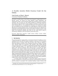
2.2 Pioneer Plat<strong>for</strong>m<br />
Figure 1: <strong>Helicopter</strong> Test-bed<br />
The onboard processing power <strong>of</strong> the Linux stack was<br />
insufficient <strong>for</strong> running the vision code, so a 1.8GHhz wireless<br />
video tr<strong>an</strong>smitter was used to tr<strong>an</strong>smit the video signal<br />
to a second ground station (a 2.4GHz Pentium IV based PC.<br />
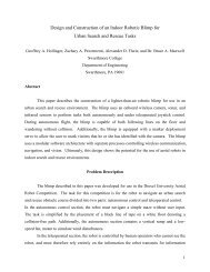
For the ground-based experiment, <strong>an</strong> Active Media Pioneer<br />
2DX was used. The Pioneer was fitted with the omnidirectional<br />
camera by mounting the camera at the end<br />
<strong>of</strong> a vertical pod 90cm above ground level (as shown in<br />
Figure 4). The camera was mounted with the lens facing<br />
downwards, as it would be on the helicopter. This resulted<br />
in a small portion <strong>of</strong> the FOV being occluded by the mount,<br />
which affected the Pioneer’s per<strong>for</strong>m<strong>an</strong>ce in completing the<br />
task (there was no such problem with mount on the helicopter<br />
however). The Pioneer is equipped with a Pentium
II 200 MHz processor, which was used to run the low-level<br />
control code. The code was run using the Player/Stage environment<br />
[17, 18]. As with the helicopter, a 1.8GHz wireless<br />
video tr<strong>an</strong>smitter was used to tr<strong>an</strong>smit the video signal<br />
to a ground station where the vision code was run. This<br />
code produced high-level control comm<strong>an</strong>ds at a rate <strong>of</strong><br />
8Hz which were tr<strong>an</strong>smitted to the Pioneer via the 802.11b<br />
wireless ethernet.<br />
Figure 5: Original Image<br />
Figure 6: Final Image<br />
Figure 4: Pioneer fitted with the Omnicam<br />
2.3 Centroid Finding Task<br />
In order to illustrate the capabilities <strong>of</strong> the omnidirectional<br />
vision system, a simple task was designed. A number<br />
<strong>of</strong> visual targets are placed in the environment surrounding<br />
a robot, <strong>an</strong>d the robot is required to locate <strong>an</strong>d move to the<br />
centroid <strong>of</strong> the targets (a point equidist<strong>an</strong>t from all targets).<br />
The task is simplified to two dimensions by placing all the<br />
targets on the same horizontal pl<strong>an</strong>e.<br />
3 Image Processing<br />
3.1 Preprocessing<br />
Be<strong>for</strong>e the feature recognition algorithm is run on the<br />
image, various image processing operations are applied to<br />
it in <strong>an</strong> attempt to highlight the salient features. A 3x3<br />
Medi<strong>an</strong>-filter is applied to remove white additive noise [19]<br />
<strong>an</strong>d preserve the edge sharpness [20]. Since much <strong>of</strong> the<br />
original image is black, the image is negated, reducing the<br />
number <strong>of</strong> regions it contains. Thresholding is applied to<br />
convert the image from greyscale to binary, <strong>an</strong>d the threshold<br />
value is chosen m<strong>an</strong>ually at run-time such that the desired<br />
features are preserved while m<strong>an</strong>y undesired features<br />
are lost. The image is then unwarped as described in Section<br />
3.2, followed by segmentation <strong>an</strong>d connected component<br />
labelling as described in [13]. Figure 5 shows the original<br />
spherical image, <strong>an</strong>d Figure 6 shows the image once<br />
the above processing has been per<strong>for</strong>med.<br />
3.2 Unwarping<br />
Our feature detection algorithm (described in Section<br />
3.3) is not invari<strong>an</strong>t to image skew, thus it was nec-<br />
essary to unwarp the spherical image obtained from the<br />
omnidirectional lens. If the geometric properties <strong>of</strong> such<br />
a lens are known, a projection function c<strong>an</strong> be calculated<br />
<strong>for</strong> per<strong>for</strong>ming the unwarping [21]. Since these properties<br />
were not known <strong>for</strong> our lens, the unwarping was per<strong>for</strong>med<br />
by mapping points on the spherical image (P x,y ) to corresponding<br />
points in the perspective image (P u,v ) using the<br />
geometrical properties <strong>of</strong> both images. (see Figure 7). This<br />
geometrical mapping was calculated <strong>for</strong> each quadr<strong>an</strong>t <strong>of</strong><br />
the spherical image. As <strong>an</strong> example, the mapping <strong>for</strong> the<br />
first quadr<strong>an</strong>t was:<br />
x = 320 + r*sin(θ)<br />
y = 240 - r*cos(θ)<br />
UnwarpMap[u + v*UNWARP_WIDTH].x = x<br />
UnwarpMap[u + v*UNWARP_WIDTH].y = y<br />
where:<br />
v goes from 0 to UNWARP_HEIGHT<br />
u goes from 0 to UNWARP_WIDTH/4<br />
θ = (u - UNWARP_WIDTH/4)*0.00416611<br />
r = 240 - 0.0000028v 3 - 0.0027v 2 + 1.1v - 0.42<br />
360<br />
0<br />
θ<br />
r<br />
Spherical Image<br />
(640x480)<br />
P(x,y)<br />
UNWARP_WIDTH<br />
P(u,v)<br />
360<br />
UNWARP_HEIGHT<br />
Unwarped Image<br />
(1754x290)<br />
Figure 7: Illustration <strong>of</strong> the Unwarping Process
3.3 Feature Recognition Using Hu’s Moments<br />
As discussed in [22], Hu’s moments c<strong>an</strong> be used <strong>for</strong> feature<br />
recognition. Once the system has been trained on a certain<br />
feature, this feature c<strong>an</strong> be recognized regardless <strong>of</strong> its<br />
orientation, scaling or tr<strong>an</strong>slation. Although this technique<br />
is not invari<strong>an</strong>t to skewing, it was found that the feature<br />
(the letter H) could still be detected when it was skewed<br />
to 45 degrees horizontally, <strong>an</strong>d 30 degrees vertically. This<br />
technique was previously used successfully <strong>for</strong> detecting<br />
the same feature painted on a helipad during autonomous<br />
vision based l<strong>an</strong>ding [13].<br />
result is that the robot moves towards the centroid <strong>of</strong> targets.<br />
Omax<br />
Robot<br />
Centroid<br />
Omin<br />
Percieved area <strong>of</strong> target<br />
Average area <strong>of</strong> targets<br />
Omax<br />
Omin<br />
4 Centroid Finding Algorithm<br />
Step 1<br />
Step 2<br />
In order to find the centroid <strong>of</strong> the visual targets, it is<br />
necessary to know the relative dist<strong>an</strong>ce to each target. Since<br />
the targets were made to be the same size, the area <strong>of</strong> each<br />
target in the image is used as <strong>an</strong> indication <strong>of</strong> the dist<strong>an</strong>ce<br />
to the target. The algorithm runs as follows:<br />
For each image:<br />
find the area <strong>an</strong>d position <strong>of</strong> each detected target (x position<br />
only, since the task is in 2D.<br />
(A 1, A 2, A 3, ...A n; X 1, X 2, X 3, ...X n)<br />
Calculate the average, maximum <strong>an</strong>d minimum areas<br />
<strong>of</strong> the targets <strong>an</strong>d the positions <strong>of</strong> largest <strong>an</strong>d smallest<br />
targets:(A ave, A max, A min), (X max, X min).<br />
while(A max - A min ≥ threshold)<br />
Calculate the <strong>of</strong>fsets from the average area to the minimum <strong>an</strong>d<br />
the maximum areas:<br />
O max = A max - A ave<br />
O min = A ave - A min<br />
determine the action to take:<br />
if O max ≥ O min<br />
move away from X max<br />
else<br />
move towards X min<br />
loop<br />
This causes the robot to move away from the closest target<br />
or move towards the farthest target, until all the targets<br />
are roughly at the same dist<strong>an</strong>ce (within threshold). A useful<br />
property <strong>of</strong> this technique is that it is not necessary to<br />
know the actual dist<strong>an</strong>ce to each target, only the relative<br />
dist<strong>an</strong>ces.<br />
Figure 8 illustrates this algorithm. Note that the size<br />
<strong>of</strong> the solid-line circles represents the relative size <strong>of</strong> the<br />
targets as seen by the robot, while the dotted-line circles<br />
represent the average size <strong>of</strong> the targets. In Step 1, O min is<br />
greater th<strong>an</strong> O max , so the robot moves towards the farthest<br />
target. By Step 2, O max becomes larger th<strong>an</strong> O min , <strong>an</strong>d<br />
the robot moves away from the closest target. The overall<br />
Figure 8: Centroid Finding Algorithm<br />
5 Experimental Setup<br />
Although the omnidirectional vision system had been<br />
developed <strong>for</strong> use on <strong>an</strong> autonomous helicopter, it was decided<br />
that the system should first be tested on a ground<br />
robot. This would help to eliminate m<strong>an</strong>y problems be<strong>for</strong>e<br />
using the system on the helicopter, as it is easier to<br />
conduct experiments <strong>an</strong>d debug the code on a ground vehicle<br />
th<strong>an</strong> a helicopter. Experiments were thus first done<br />
on the Pioneer robot, <strong>an</strong>d once the robot could complete<br />
the centroid finding task consistently, the experiment was<br />
conducted on the helicopter. Although autonomous flight<br />
was not yet possible with our new helicopter plat<strong>for</strong>m, data<br />
could be collected from all the onboard sensors. The helicopter<br />
was flown under pilot control in the vicinity <strong>of</strong> the<br />
visual targets while the centroid finding algorithm was run.<br />
The GPS coordinates <strong>an</strong>d heading <strong>of</strong> the helicopter were<br />
logged as well as the comm<strong>an</strong>ds that were being generated<br />
by the algorithm. After the test flights the data were <strong>an</strong>alyzed<br />
to see if appropriate control comm<strong>an</strong>ds were being<br />
generated by the algorithm (the GPS coordinate <strong>of</strong> the centroid<br />
had been recorded, <strong>an</strong>d the helicopter’s heading <strong>an</strong>d<br />
location were compared to this).<br />
For the Pioneer-based experiment, a 23x17cm white H<br />
on a black background was used as the visual target. This<br />
version <strong>of</strong> the experiment was designed to be a scaleddown<br />
version <strong>of</strong> the outdoor one - since the targets would<br />
be much closer to the Pioneer, their size was reduced accordingly<br />
. The scale <strong>of</strong> the outdoor experiment (i.e. the<br />
maximum dist<strong>an</strong>ce that the targets could be from the helicopter<br />
<strong>for</strong> effective recognition) was determined by the<br />
resolution <strong>of</strong> the camera <strong>an</strong>d size that the outdoor targets<br />
could be made (83x70cm). For the outdoor experiment, the<br />
targets were placed on the circumference <strong>of</strong> a circle with a<br />
diameter <strong>of</strong> 12.2m. For the indoor experiment, the diameter<br />
was reduced to 2.5m.
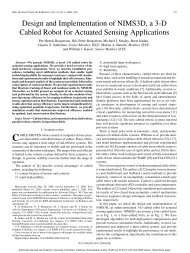
350<br />
300<br />
250<br />
Amax<br />
Area (pixels)<br />
200<br />
150<br />
100<br />
Aave<br />
50<br />
Amin<br />
0<br />
0 20 40 60 80 100 120 140 160 180<br />
Time (s)<br />
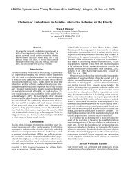
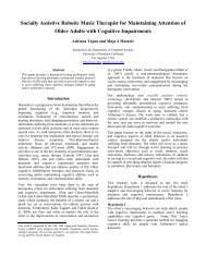
Figure 9: <strong>Helicopter</strong> Experiment being Conducted<br />
Figure 11: Ave, Max <strong>an</strong>d Min target areas over time<br />
that had been correctly detected. In a total <strong>of</strong> 25 frames,<br />
48% <strong>of</strong> the H’s were detected, <strong>an</strong>d no false detections were<br />
made.<br />
6.2 <strong>Helicopter</strong><br />
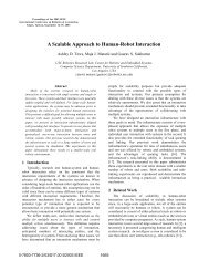
Figure 10: Pioneer Experiment being Conducted<br />
6 Experimental Results<br />
6.1 Pioneer<br />
The experiment using the Pioneer robot was conducted<br />
by placing the robot in a position where it could see the<br />
visual targets, but not at the centroid <strong>of</strong> the targets. The algorithm<br />
was then run as the robot attempted to locate <strong>an</strong>d<br />
move towards the centroid <strong>of</strong> the targets. The task was considered<br />
completed when the robot had stabilized within 20<br />
cm <strong>of</strong> the true centroid <strong>of</strong> the targets. 20 such runs were<br />
completed. The areas <strong>of</strong> the detected targets were recorded<br />
at 1s intervals, as well as the time <strong>for</strong> completing each task.<br />
Since the experiment was conducted indoors, GPS could<br />
not be used to determine the position <strong>of</strong> the robot relative<br />
to the centroid. As <strong>an</strong> alternative indication <strong>of</strong> the effectiveness<br />
<strong>of</strong> the algorithm, the Average, Minimum <strong>an</strong>d Maximum<br />
areas are plotted against time. Figure 11, is <strong>an</strong> example<br />
<strong>of</strong> such a plot <strong>an</strong>d shows that the Max <strong>an</strong>d Min values<br />
converge towards the Ave value, indicating that the robot<br />
converges to a point approximately equidist<strong>an</strong>t from all the<br />
targets.<br />
The effectiveness <strong>of</strong> the feature recognition algorithm<br />
was also evaluated by examining a number <strong>of</strong> the raw <strong>an</strong>d<br />
processed frames captured, <strong>an</strong>d noting the number <strong>of</strong> H’s<br />
Four test flights were completed as described in Section<br />
5. The data were <strong>an</strong>alyzed by looking <strong>for</strong> inst<strong>an</strong>ces<br />
where at least 2 H’s had been detected, noting the helicopter’s<br />
position <strong>an</strong>d heading at that time, as well as the<br />
control comm<strong>an</strong>d that was being generated. If the comm<strong>an</strong>d<br />
was trying to move the helicopter towards the centroid<br />
<strong>of</strong> the targets, it was considered to be correct. The<br />
<strong>an</strong>alysis showed that appropriate comm<strong>an</strong>ds were generated<br />
90% <strong>of</strong> the time.<br />
Figure 12 shows a spherical image taken during flight<br />
as well as the corresponding processed image. The lines<br />
drawn from the center <strong>of</strong> the processed image to the H’s<br />
indicates that the H’s have been identified. The vertical<br />
line shows the desired heading <strong>for</strong> the control comm<strong>an</strong>d<br />
that has been generated <strong>for</strong> this image.<br />
As <strong>for</strong> the ground-based experiment, the effectiveness <strong>of</strong><br />
the feature recognition technique was evaluated. In a total<br />
<strong>of</strong> 25 frames, 38% <strong>of</strong> the H’s were detected, <strong>an</strong>d 8 false<br />
detections were made.<br />
7 Conclusion <strong>an</strong>d Future Work<br />
We have presented the design <strong>an</strong>d implementation <strong>of</strong> a<br />
sideways-looking sensor <strong>for</strong> <strong>an</strong> autonomous helicopter using<br />
<strong>an</strong> omnidirectional vision system. The effectiveness <strong>of</strong><br />
the system was demonstrated by completing a visual servoing<br />
task that required a number <strong>of</strong> features to be identified<br />
simult<strong>an</strong>eously within a large field <strong>of</strong> view in the environment.<br />
Data from several experiments show that the task<br />
was completed successfully on a ground based robot. It
Figure 12: Images Taken During Flight<br />
was shown that the vision system <strong>an</strong>d centroid finding algorithm<br />
could generate appropriate control comm<strong>an</strong>ds when<br />
tested on a pilot-controlled model helicopter. In the future<br />
we pl<strong>an</strong> to run the full experiment on the helicopter when<br />
it is flying autonomously.<br />
Once we have achieved omnidirectional vision-based<br />
control <strong>of</strong> the helicopter we intend to use this capability<br />
<strong>for</strong> tasks such as flying between obstacles (such as buildings)<br />
<strong>an</strong>d visually servoing into position to monitor <strong>an</strong> area<br />
<strong>of</strong> interest (such as a specific window on a building).<br />
Acknowledgments<br />
This work is sponsored in part by NASA under<br />
JPL/Caltech contract 1231521 <strong>an</strong>d by DARPA gr<strong>an</strong>ts<br />
DABT63-99-1-0015 <strong>an</strong>d 5-39509-A (via UPenn) under the<br />
MARS program. We th<strong>an</strong>k Doug Wilson <strong>for</strong> support with<br />
flight trials.<br />
References<br />
[1] Larry Matthies Charles Bergh, Brett Kennedy <strong>an</strong>d Andrew<br />
Johnson, “A compact, low power two-axis sc<strong>an</strong>ning laser<br />
r<strong>an</strong>gefinder <strong>for</strong> mobile robots,” September 2000.<br />
[2] Ry<strong>an</strong> Miller <strong>an</strong>d Omead Amidi, “3-d site mapping with the<br />
cmu autonomous helicopter,” in In Proceedings <strong>of</strong> 5th International<br />
Conference on Intelligent <strong>Autonomous</strong> Systmes,<br />
June 1998.<br />
[3] Gregory D. Hager <strong>an</strong>d Peter N. Belhumeur, “Efficient region<br />
tracking with parametric models <strong>of</strong> geometry <strong>an</strong>d illumination,”<br />
IEEE Tr<strong>an</strong>sactions on Pattern Analysis <strong>an</strong>d Machine<br />
Intelligence, vol. 20, no. 10, pp. 1025–1039, 1998.<br />
[4] S. Baker <strong>an</strong>d S. Nayar, “A theory <strong>of</strong> catadioptric image <strong>for</strong>mation,”<br />
in Proceedings <strong>of</strong> ICCV, Bombay, India, J<strong>an</strong>uary<br />
1998, pp. 35–42.<br />
[5] Terry Boult, “Frame-rate omnidirectional surveill<strong>an</strong>ce<br />
tracking, http://www.cse.lehigh.edu/ tboult/track/,” .<br />
[6] Y. Yagi, “<strong>Omnidirectional</strong> sensing <strong>an</strong>d its applications,”<br />
in IEICE Tr<strong>an</strong>sactions On In<strong>for</strong>mation And Systems, vol.<br />
E82D, no. 3, pp. 568-579, Mar.1999.<br />
[7] Peng Ch<strong>an</strong>g <strong>an</strong>d Martial Hebert, “Omni-directional visual<br />
servoing <strong>for</strong> hum<strong>an</strong>-robot interaction,” in Proceedings <strong>of</strong><br />
the 1998 IEEE/RSJ International Conference on Intelligent<br />
Robots <strong>an</strong>d Systems (IROS ’98), October 1998, vol. 3, pp.<br />
1801 – 1807.<br />
[8] T. K<strong>an</strong>ade, R. Collins, A. Lipton, P. Burt, <strong>an</strong>d L. Wixson,<br />
“Adv<strong>an</strong>ces in cooperative multi-sensor video surveill<strong>an</strong>ce,”<br />
in In Proceedings <strong>of</strong> DARPA Image Underst<strong>an</strong>ding Workshop,<br />
volume 1, pages 3–24, November 1998.<br />
[9] N. Winters, J. Gaspar, G. Lacey, <strong>an</strong>d J. S<strong>an</strong>tos-Victor,<br />
“Omni-directional vision <strong>for</strong> robot navigation,” in Proc.<br />
IEEE Workshop on <strong>Omnidirectional</strong> <strong>Vision</strong> - Omnivis00,<br />
2000.<br />
[10] S.B. K<strong>an</strong>g <strong>an</strong>d R. Szeliski, “3-d scene data recovery using<br />
omnidirectional multibaseline stereo,” in IEEE Conference<br />
on Computer <strong>Vision</strong> <strong>an</strong>d Pattern Recogstruction, 1996, pp.<br />
364–370.<br />
[11] Rol<strong>an</strong>d Bunschoten <strong>an</strong>d Ben Krse, “3-d scene reconstruction<br />
from cylindrical p<strong>an</strong>oramic images,” .<br />
[12] Wasinee Rungsarityotin <strong>an</strong>d Thad Starner, “Finding location<br />
using omnidirectional video on a wearable computing<br />
plat<strong>for</strong>m,” in ISWC, 2000, pp. 61–68.<br />
[13] S. Saripalli, J. F. Montgomery, <strong>an</strong>d G. S. Sukhatme, “<strong>Vision</strong>based<br />
autonomous l<strong>an</strong>ding <strong>of</strong> <strong>an</strong> unm<strong>an</strong>ned aerial vehicle,”<br />
in IEEE International Conference on Robotics <strong>an</strong>d Automation,<br />
Washington D.C., May 2002, pp. 2799–2804.<br />
[14] C. Sharp, O. Shakernia, <strong>an</strong>d S. Sastry, “A vision system<br />
<strong>for</strong> l<strong>an</strong>ding <strong>an</strong> unm<strong>an</strong>ned aerial vehicle,” in In Proceedings<br />
<strong>of</strong> IEEE International Conference on Robotics <strong>an</strong>d Automation,<br />
2001, pp. 1720-1728.<br />
[15] Pedro J.Garcia-Padro, Gaurav S.Sukhatme, <strong>an</strong>d<br />
J.F.Montgomery, “Towards vision-based safe l<strong>an</strong>ding<br />
<strong>for</strong> <strong>an</strong> autonomous helicopter,” Robotics <strong>an</strong>d <strong>Autonomous</strong><br />
Systems, 2000, (accepted, to appear).<br />
[16] USC <strong>Autonomous</strong> Flying Vehicle Homepage, “http://wwwrobotics.usc.edu/˜avatar,”<br />
.<br />
[17] B.P. Gerkey K. Sty R.T. Vaugh<strong>an</strong> A.Howard G.S. Sukhatme<br />
<strong>an</strong>d M.J. MAtaric, “Most valuable player: A robot device<br />
server <strong>for</strong> distributed control,” in IEEE/RSJ Intl. Conf.<br />
On Intelligent Robots <strong>an</strong>d Systems (IROS), Wailea, Hawaii,<br />
2001.<br />
[18] R.T. Vaugh<strong>an</strong>, “Stage: A multiple robot simulator,” in Tech.<br />
Rep. IRIS-00-393, Institute <strong>for</strong> Robotics <strong>an</strong>d Intelligent Systems,<strong>University</strong><br />
<strong>of</strong> Southern Cali<strong>for</strong>nia, 2000.<br />
[19] R.Gonzalez <strong>an</strong>d R.Woods, Digital Image Processing,<br />
Addison-Wesley, 1992.<br />
[20] Io<strong>an</strong>nis Pitas, Digital Image Processing Algorithms,<br />
Prentice-Hall, 1993.<br />
[21] J. Gaspar, N. Winters, <strong>an</strong>d J. S<strong>an</strong>tos-Victor, “<strong>Vision</strong>-based<br />
navigation <strong>an</strong>d environmental representations with <strong>an</strong> omnidirectional<br />
camera,” in In IEEE Tr<strong>an</strong>sactions on Robotics<br />
<strong>an</strong>d Automation, 16(6):890–898, 2000.<br />
[22] M.K.Hu, “Visual pattern recognition by moment invari<strong>an</strong>ts,”<br />
in IRE Tr<strong>an</strong>sactions on In<strong>for</strong>mation Theory, 1962,<br />
vol. IT-8, pp. 179–187.