Design and construction of an indoor robotic blimp for urban search ...
Design and construction of an indoor robotic blimp for urban search ...
Design and construction of an indoor robotic blimp for urban search ...
Create successful ePaper yourself
Turn your PDF publications into a flip-book with our unique Google optimized e-Paper software.
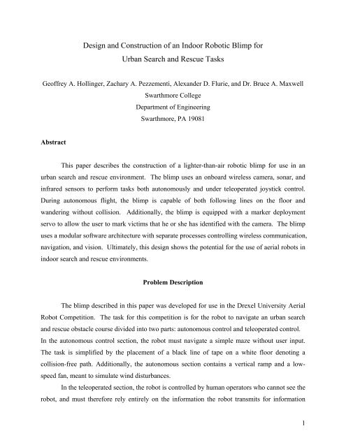
<strong>Design</strong> <strong><strong>an</strong>d</strong> Construction <strong>of</strong> <strong>an</strong> Indoor Robotic Blimp <strong>for</strong><br />
Urb<strong>an</strong> Search <strong><strong>an</strong>d</strong> Rescue Tasks<br />
Ge<strong>of</strong>frey A. Hollinger, Zachary A. Pezzementi, Alex<strong><strong>an</strong>d</strong>er D. Flurie, <strong><strong>an</strong>d</strong> Dr. Bruce A. Maxwell<br />
Swarthmore College<br />
Department <strong>of</strong> Engineering<br />
Swarthmore, PA 19081<br />
Abstract<br />
This paper describes the <strong>construction</strong> <strong>of</strong> a lighter-th<strong>an</strong>-air <strong>robotic</strong> <strong>blimp</strong> <strong>for</strong> use in <strong>an</strong><br />
urb<strong>an</strong> <strong>search</strong> <strong><strong>an</strong>d</strong> rescue environment. The <strong>blimp</strong> uses <strong>an</strong> onboard wireless camera, sonar, <strong><strong>an</strong>d</strong><br />
infrared sensors to per<strong>for</strong>m tasks both autonomously <strong><strong>an</strong>d</strong> under teleoperated joystick control.<br />
During autonomous flight, the <strong>blimp</strong> is capable <strong>of</strong> both following lines on the floor <strong><strong>an</strong>d</strong><br />
w<strong><strong>an</strong>d</strong>ering without collision. Additionally, the <strong>blimp</strong> is equipped with a marker deployment<br />
servo to allow the user to mark victims that he or she has identified with the camera. The <strong>blimp</strong><br />
uses a modular s<strong>of</strong>tware architecture with separate processes controlling wireless communication,<br />
navigation, <strong><strong>an</strong>d</strong> vision. Ultimately, this design shows the potential <strong>for</strong> the use <strong>of</strong> aerial robots in<br />
<strong>indoor</strong> <strong>search</strong> <strong><strong>an</strong>d</strong> rescue environments.<br />
Problem Description<br />
The <strong>blimp</strong> described in this paper was developed <strong>for</strong> use in the Drexel University Aerial<br />
Robot Competition. The task <strong>for</strong> this competition is <strong>for</strong> the robot to navigate <strong>an</strong> urb<strong>an</strong> <strong>search</strong><br />
<strong><strong>an</strong>d</strong> rescue obstacle course divided into two parts: autonomous control <strong><strong>an</strong>d</strong> teleoperated control.<br />
In the autonomous control section, the robot must navigate a simple maze without user input.<br />
The task is simplified by the placement <strong>of</strong> a black line <strong>of</strong> tape on a white floor denoting a<br />
collision-free path. Additionally, the autonomous section contains a vertical ramp <strong><strong>an</strong>d</strong> a lowspeed<br />
f<strong>an</strong>, me<strong>an</strong>t to simulate wind disturb<strong>an</strong>ces.<br />
In the teleoperated section, the robot is controlled by hum<strong>an</strong> operators who c<strong>an</strong>not see the<br />
robot, <strong><strong>an</strong>d</strong> must there<strong>for</strong>e rely entirely on the in<strong>for</strong>mation the robot tr<strong>an</strong>smits <strong>for</strong> in<strong>for</strong>mation<br />
1
about the robot <strong><strong>an</strong>d</strong> its environment. Several “victims” are scattered about this portion <strong>of</strong> the gym,<br />
<strong><strong>an</strong>d</strong> the objective is <strong>for</strong> the robot to drop markers as close as possible to each victim. The<br />
obstacle course described above provides a good sampling <strong>of</strong> the necessary tasks that a <strong>blimp</strong><br />
would need to per<strong>for</strong>m in a real urb<strong>an</strong> <strong>search</strong> <strong><strong>an</strong>d</strong> rescue situation.<br />
Introduction<br />
In <strong>indoor</strong> urb<strong>an</strong> <strong>search</strong> <strong><strong>an</strong>d</strong> rescue environments, it is <strong>of</strong>ten necessary <strong>for</strong> robots to move<br />
in the vertical direction to ascend staircases or move between floors. In cluttered <strong>indoor</strong><br />
environments, such as a collapsed building, airpl<strong>an</strong>es <strong><strong>an</strong>d</strong> other low-m<strong>an</strong>euverability craft cease<br />
to be a feasible option. Additionally, most helicopter designs run the d<strong>an</strong>ger <strong>of</strong> destroying<br />
themselves during collision with walls or fallen obstacles. The remaining option <strong>for</strong> aerial<br />
<strong>search</strong> <strong><strong>an</strong>d</strong> rescue is a lighter-th<strong>an</strong>-air <strong>blimp</strong>. Helium is safe <strong><strong>an</strong>d</strong> readily available, <strong><strong>an</strong>d</strong> current<br />
miniaturization allows <strong>for</strong> sophisticated electronics to be placed on a <strong>blimp</strong> small enough to be<br />
used <strong>indoor</strong>s. Blimp robots also have the adv<strong>an</strong>tage <strong>of</strong> flying at neutral buoy<strong>an</strong>cy without active<br />
vertical stabilization, <strong><strong>an</strong>d</strong> they are <strong>of</strong>ten capable <strong>of</strong> colliding with obstacles without damaging<br />
themselves. Furthermore, wireless cameras <strong><strong>an</strong>d</strong> sensing equipment c<strong>an</strong> be easily mounted on<br />
<strong>blimp</strong>s to provide import<strong>an</strong>t in<strong>for</strong>mation about unknown environments.<br />
M<strong>an</strong>y aerial <strong>robotic</strong>s labs are not focused at all on <strong>blimp</strong>s. The BEAR lab at the<br />
University <strong>of</strong> Cali<strong>for</strong>nia, Berkeley <strong><strong>an</strong>d</strong> the UAV lab at the Georgia Institute <strong>of</strong> Technology work<br />
primarily with outdoor rotorcraft. Despite this, <strong>indoor</strong> airships have had some mention in<br />
literature. They have been considered <strong>for</strong> chassis in work on bio-inspired navigation, <strong><strong>an</strong>d</strong> m<strong>an</strong>y<br />
<strong>of</strong> the obvious adv<strong>an</strong>tages are mentioned [18]. Much <strong>of</strong> the previous work with lighter-th<strong>an</strong>-air<br />
robots, however, has been predominately in outdoor environments. The University <strong>of</strong><br />
Pennsylv<strong>an</strong>ia GRASP Blimp, <strong>for</strong> inst<strong>an</strong>ce, uses visual servoing, GPS, <strong><strong>an</strong>d</strong> f<strong>an</strong> encoders to<br />
control <strong><strong>an</strong>d</strong> localize itself while flying outdoors [11]. This large <strong>blimp</strong> has a volume <strong>of</strong> 26 cu. m<br />
(the size <strong>of</strong> a small room) <strong><strong>an</strong>d</strong> carries a subst<strong>an</strong>tial payload making its use impossible <strong>indoor</strong>s.<br />
When developing <strong>indoor</strong> <strong>blimp</strong>s, it is <strong>of</strong>ten necessary to implement complex behaviors<br />
involving decisions based on more in<strong>for</strong>mation th<strong>an</strong> is immediately available from sensors. To<br />
accomplish this, some <strong>for</strong>m <strong>of</strong> odometry is necessary. Most robot systems use GPS systems or<br />
wheel encoders <strong>for</strong> odometric in<strong>for</strong>mation [11][18]. Neither <strong>of</strong> these solutions are options <strong>for</strong><br />
2
<strong>indoor</strong> aerial robots, since GPS systems do not work in <strong>indoor</strong> environments <strong><strong>an</strong>d</strong> aerial robots<br />
have no wheels. It is possible, however, to recover motion in<strong>for</strong>mation from video, <strong><strong>an</strong>d</strong> visual<br />
odometry has been used successfully in a variety <strong>of</strong> robot applications.<br />
Without visual odometry, autonomous operation is also possible by following fixed<br />
markers such as lines. The task <strong>of</strong> line following c<strong>an</strong> be broken up into two parts: extracting the<br />
line from <strong>an</strong> image <strong><strong>an</strong>d</strong> sending control signals to move along the line. The choice <strong>of</strong> the line<br />
extraction method constrains the other, since it determines the <strong>for</strong>mat <strong>of</strong> the data that will be sent<br />
to the control system.<br />
Line extraction has generally been thought <strong>of</strong> as edge detection with the refinement <strong>of</strong><br />
<strong>search</strong>ing <strong>for</strong> straight edges. Two algorithms have primarily been applied to this problem, the<br />
C<strong>an</strong>ny detector [2] <strong><strong>an</strong>d</strong> the Hough tr<strong>an</strong>s<strong>for</strong>m [7]. The Hough tr<strong>an</strong>s<strong>for</strong>m is a vote-taking scheme<br />
which will be described in detail in the Line Following section. The Hough tr<strong>an</strong>s<strong>for</strong>m has<br />
adv<strong>an</strong>tages in robustness to noise, ease <strong>of</strong> implementation, <strong><strong>an</strong>d</strong> easy evaluation <strong>of</strong> the quality <strong>of</strong> a<br />
line detection. Its main disadv<strong>an</strong>tages are that it is computationally expensive, it c<strong>an</strong> only detect<br />
lines but not line segments, <strong><strong>an</strong>d</strong> the C<strong>an</strong>ny detector better h<strong><strong>an</strong>d</strong>les the presence <strong>of</strong> multiple lines<br />
in the image. Only the computational expense is a major factor in the line following domain<br />
though. For these reasons the Hough tr<strong>an</strong>s<strong>for</strong>m has become the st<strong><strong>an</strong>d</strong>ard method <strong>of</strong> line<br />
extraction [8], <strong><strong>an</strong>d</strong> it has been used in the line following algorithms <strong>of</strong> several robot systems<br />
[3][4]. It was also there<strong>for</strong>e the method chosen <strong>for</strong> the system described in this paper.<br />
Hardware Considerations<br />
Blimp Bag <strong><strong>an</strong>d</strong> Lifting Agent<br />
When developing the <strong>blimp</strong>, the primary hardware constraint was the mass it is able to<br />
support. It was initially decided to use helium as the lifting agent, but a suggestion was made to<br />
use a helium/hydrogen mix that would allow <strong>for</strong> more lift given the same volume <strong>of</strong> gas. Helium<br />
at STP lifts 1.03 g/L, but balloon bags are over-pressurized, leading to a lift <strong>of</strong> approximately<br />
1.023 g/L. Hydrogen, on the other h<strong><strong>an</strong>d</strong>, lifts 1.12 g/L at STP, or approximately 1.11 g/L when<br />
over-pressurized. Hydrogen is inflammable, but care in h<strong><strong>an</strong>d</strong>ling should allow <strong>for</strong> a small<br />
increase in lift potential. The bags used are 52” ellipsoidal mylar balloons. The bags have <strong>an</strong><br />
3
inflated volume <strong>of</strong> approximately 184 L, which allows <strong>for</strong> 188.2 g to be lifted <strong>for</strong> a helium-filled<br />
balloon. The bag <strong><strong>an</strong>d</strong> fins weight 72.0 g, allowing <strong>for</strong> 116.2 g <strong>of</strong> extra lift <strong>for</strong> components with<br />
one bag.<br />
Hardware Overview<br />
Ground-Side<br />
A PC running Linux was used to process sensor data <strong><strong>an</strong>d</strong> send control signals to the<br />
<strong>blimp</strong>. A Total Robots Wireless Control Module (WCM) network was used <strong>for</strong> sensor data<br />
communication <strong><strong>an</strong>d</strong> <strong>blimp</strong>-side servo control. 1 Both a remote control that sends the motor control<br />
signals <strong><strong>an</strong>d</strong> the WCM are connected to serial ports <strong>of</strong> the PC.<br />
Blimp-Side<br />
The <strong>blimp</strong> hardware was designed to allow <strong>for</strong> completion <strong>of</strong> both the teleoperated <strong><strong>an</strong>d</strong><br />
autonomous sections. The undercarriage, <strong>blimp</strong> motors, <strong><strong>an</strong>d</strong> batteries are mounted on the bottom<br />
<strong>of</strong> the <strong>blimp</strong> with infrared sensors on the sides <strong><strong>an</strong>d</strong> a sonar on the front. The WCM <strong><strong>an</strong>d</strong> marker<br />
deployer are placed behind the undercarriage towards the back <strong>of</strong> the <strong>blimp</strong>. The camera is<br />
placed at the very front <strong>of</strong> the <strong>blimp</strong>. Figure 1 shows a diagram <strong>of</strong> the <strong>blimp</strong> configuration.<br />
Figure 1: Diagram <strong>of</strong> <strong>blimp</strong> configuration<br />
1 More detailed in<strong>for</strong>mation about the WCM network may be found in its own section.<br />
4
Hardware <strong>for</strong> use on the <strong>blimp</strong> was chosen based upon its utility in simple line- <strong><strong>an</strong>d</strong><br />
space-following configurations <strong><strong>an</strong>d</strong> its weight. The sonar has a wide window <strong>of</strong> detection,<br />
r<strong>an</strong>ging from a few centimeters to 4 meters <strong><strong>an</strong>d</strong> is lightweight. The IRs are also lightweight <strong><strong>an</strong>d</strong><br />
long r<strong>an</strong>ge, reaching as far as 2 meters. The eyecam was <strong>an</strong> extremely lightweight <strong>blimp</strong>-side<br />
package <strong><strong>an</strong>d</strong> <strong>of</strong>fered the best quality in r<strong>an</strong>ge <strong><strong>an</strong>d</strong> picture <strong>of</strong> the possible cameras within the<br />
budget <strong>of</strong> the project. A small picoservo was used <strong>for</strong> the deployment <strong>of</strong> the rescue markers in<br />
the teleoperated section <strong>of</strong> the course.<br />
The picoservo, a plastic cross-shaped loading carriage, <strong><strong>an</strong>d</strong> a plastic tube make up the<br />
teleoperated section’s marker deployment system. This system relies on the servo’s ability to<br />
simult<strong>an</strong>eously load <strong><strong>an</strong>d</strong> launch a marker in one motion. This is achieved by creating markers<br />
that are the exact size <strong>of</strong> the loading carriage attached to the servo such that only one marker is<br />
loaded at a time. The motion is sufficiently quick that extra markers do not deploy while one is<br />
being launched, <strong><strong>an</strong>d</strong> the carriage is walled sufficiently to avoid the unw<strong>an</strong>ted dropping <strong>of</strong> badlypositioned<br />
markers.<br />
Hardware Configuration<br />
The barebones configuration <strong>for</strong> m<strong>an</strong>ually-operated flight requires only the undercarriage<br />
<strong><strong>an</strong>d</strong> sufficient ballast to bring the craft to neutral buoy<strong>an</strong>cy. This allows m<strong>an</strong>ual control <strong>of</strong> a<br />
balloon using the remote, <strong><strong>an</strong>d</strong> this configuration is implemented during the m<strong>an</strong>ual control<br />
section <strong>of</strong> the competition.<br />
The configuration <strong>for</strong> simple teleoperated control requires the camera, the 9V battery <strong>for</strong><br />
powering the camera, the undercarriage, <strong><strong>an</strong>d</strong> <strong>an</strong>y extra ballast needed. This allows teleoperated<br />
control <strong>of</strong> a balloon using the nav module <strong><strong>an</strong>d</strong> the computer joystick interface. The addition <strong>of</strong><br />
the WCM, the 6V battery, <strong><strong>an</strong>d</strong> the picoservo marker deployment system allows the teleoperated,<br />
<strong>search</strong>-<strong><strong>an</strong>d</strong>-rescue section <strong>of</strong> the course to be completed.<br />
The configuration <strong>for</strong> autonomous line-, space-, or wall-following requires the camera,<br />
the sonar, the IR sensors, the 9V battery, the undercarriage, the WCM, <strong><strong>an</strong>d</strong> the 6V battery. The<br />
only piece <strong>of</strong> equipment not vital to autonomous functionality is the marker deployment system.<br />
5
Wireless Communication Module<br />
To tr<strong>an</strong>smit sensor data <strong><strong>an</strong>d</strong> deployer positions between the <strong>blimp</strong> <strong><strong>an</strong>d</strong> the host computer,<br />
a wireless communication module (WCM) was used. In autonomous mode, 2 the mode used in<br />
this paper, the registers <strong>of</strong> the <strong>blimp</strong> WCM mimic those <strong>of</strong> the WCM connected to the server<br />
computer through the RS232 port. The WCM network tr<strong>an</strong>smits in<strong>for</strong>mation wirelessly at 2.4<br />
GHz <strong><strong>an</strong>d</strong> allows <strong>for</strong> up to four <strong>an</strong>alog sensors <strong><strong>an</strong>d</strong> eight digital I/O devices (including servo<br />
motors). On the server side, the host computer communicates with the WCM asynchronously<br />
using a serial protocol. The host computer c<strong>an</strong> both write to <strong><strong>an</strong>d</strong> read from the WCM using this<br />
protocol. Additionally, the WCM weighs less th<strong>an</strong> 40 grams, making it ideal <strong>for</strong> use on the<br />
<strong>blimp</strong>. Figure 2 gives a picture <strong>of</strong> the WCM <strong><strong>an</strong>d</strong> a diagram <strong>of</strong> its operation.<br />
Figure 2: Picture <strong>of</strong> WCM (left) <strong><strong>an</strong>d</strong> diagram <strong>of</strong> WCM operation (right)<br />
In the final <strong>blimp</strong> configuration, two infrared sensors <strong><strong>an</strong>d</strong> one sonar were connected to<br />
the WCM’s <strong>an</strong>alog input ports. The servo motor <strong>for</strong> marker deployment was connected to one <strong>of</strong><br />
the I/O ports. Using the WCM s<strong>of</strong>tware module, described in the next section, the host computer<br />
calls <strong>for</strong> the reads <strong><strong>an</strong>d</strong> writes necessary to retrieve sensor data <strong><strong>an</strong>d</strong> deploy markers.<br />
2 Other modes are available <strong>for</strong> the WCM. For more in<strong>for</strong>mation, examine the datasheet at www.totalrobots.com.<br />
6
Host Computer S<strong>of</strong>tware Architecture<br />
In the design <strong>of</strong> the <strong>blimp</strong>’s s<strong>of</strong>tware architecture, it was necessary to separate the visual<br />
processing, navigation control, <strong><strong>an</strong>d</strong> wireless communication because a simple program could not<br />
per<strong>for</strong>m all <strong>of</strong> these tasks simult<strong>an</strong>eously without unnecessary delay. To optimize the operating<br />
frequency <strong>of</strong> each task, a modular s<strong>of</strong>tware architecture was implemented. The navigation<br />
module h<strong><strong>an</strong>d</strong>les communication with the <strong>blimp</strong>’s motors <strong><strong>an</strong>d</strong> makes control decisions during<br />
autonomous operation. The wireless communication module reads sensor data <strong><strong>an</strong>d</strong> writes servo<br />
positions to the wireless device on the <strong>blimp</strong>. Finally, the vision module, h<strong><strong>an</strong>d</strong>les image<br />
processing <strong><strong>an</strong>d</strong> line-following. Figure 3 gives a diagram <strong>of</strong> the <strong>blimp</strong> module structure.<br />
Figure 3: GCM module structure <strong>of</strong> <strong>blimp</strong><br />
Each <strong>of</strong> the processes described above were set to communicate using the IPC network<br />
protocol [15]. The IPC protocol has been successfully applied to multi-robot systems <strong><strong>an</strong>d</strong> other<br />
robot communication tasks [12]. The use <strong>of</strong> IPC communication <strong>for</strong> the <strong>blimp</strong> s<strong>of</strong>tware was<br />
facilitated by the use <strong>of</strong> the General Communications Module (GCM) developed at Swarthmore<br />
College [6]. GCM allows separate processes to asynchronously share in<strong>for</strong>mation about the state<br />
7
<strong>of</strong> the robot without delaying their operation. On the <strong>blimp</strong>, each module is allowed to run at a<br />
fixed frequency without unnecessarily waiting <strong>for</strong> updated in<strong>for</strong>mation from the other modules.<br />
If the wireless communications module stops sending in<strong>for</strong>mation, <strong>for</strong> inst<strong>an</strong>ce, the navigation<br />
<strong><strong>an</strong>d</strong> vision modules are able to continue operation.<br />
Teleoperated Joystick Interface<br />
To per<strong>for</strong>m the tasks necessary <strong>for</strong> the teleoperated portion <strong>of</strong> the competition, a joystick<br />
interface was implemented using the SDL (Simple DirectMedia Layer) library. SDL allows <strong>for</strong><br />
low-level access to the joystick by h<strong><strong>an</strong>d</strong>ling events such as button press <strong><strong>an</strong>d</strong> axis motion. SDL<br />
functions give the <strong>blimp</strong> s<strong>of</strong>tware direct access to the state <strong>of</strong> joystick buttons <strong><strong>an</strong>d</strong> the positions<br />
<strong>of</strong> the axes. A Logitech Wingm<strong>an</strong> joystick was used to operate the <strong>blimp</strong>, <strong><strong>an</strong>d</strong> buttons on the<br />
joystick were specified to drop markers <strong><strong>an</strong>d</strong> to move in the vertical directions. Additionally, a<br />
linear function <strong>of</strong> the positions <strong>of</strong> the joystick axes was used to determine the rotational <strong><strong>an</strong>d</strong><br />
tr<strong>an</strong>slational velocities <strong>of</strong> the <strong>blimp</strong>. Using GCM, the joystick module is able to easily<br />
communicate with the wireless communication module <strong><strong>an</strong>d</strong> the navigation module. This<br />
implementation provides <strong>an</strong> intuitive interface <strong>for</strong> the user to operate the <strong>blimp</strong> while viewing the<br />
wireless video. Figure 4 shows a diagram <strong>of</strong> the joystick mappings.<br />
Figure 4: Joystick interface <strong>for</strong> teleoperated <strong>blimp</strong> control<br />
8
Visual Line-Following<br />
In order to navigate the autonomous portion <strong>of</strong> the course, a line following algorithm was<br />
implemented. The line following task c<strong>an</strong> be divided into two parts, that <strong>of</strong> detecting the line <strong><strong>an</strong>d</strong><br />
that <strong>of</strong> controlling the robot to follow the line. The line extraction was accomplished using a<br />
Hough tr<strong>an</strong>s<strong>for</strong>m as described below, <strong><strong>an</strong>d</strong> the controller went through two incarnations.<br />
Figure 5. Input grayscale image (left), + <strong><strong>an</strong>d</strong> - gradient images (middle <strong><strong>an</strong>d</strong> right)<br />
The line extractor takes as input <strong>an</strong> image from the camera mounted on the front <strong>of</strong> the<br />
<strong>blimp</strong>. First, this image was converted to grayscale. Sobel-x gradient filters were then applied to<br />
the image two create two edge images, one <strong>of</strong> large positive gradients <strong><strong>an</strong>d</strong> one <strong>of</strong> large negative<br />
gradients (Figure 5). Hough tr<strong>an</strong>s<strong>for</strong>ms were applied to each <strong>of</strong> these edge images, defining a<br />
line by <strong>an</strong>gle <strong>of</strong> orientation <strong><strong>an</strong>d</strong> perpendicular dist<strong>an</strong>ce from the center <strong>of</strong> the image. A Hough<br />
tr<strong>an</strong>s<strong>for</strong>m is a pattern-matching algorithm that works through vote-taking. The pattern <strong>search</strong>ed<br />
<strong>for</strong> was a line in each <strong>of</strong> the edge images. The r<strong>an</strong>ge <strong>of</strong> <strong>an</strong>gles 0 to 2π was discretized as well as<br />
the r<strong>an</strong>ge <strong>of</strong> possible perpendicular dist<strong>an</strong>ces within <strong>an</strong> image. These two r<strong>an</strong>ges defined the x-<br />
<strong><strong>an</strong>d</strong> y-dimensions <strong>of</strong> the Hough accumulator, which allows the parametrization <strong>of</strong> a line by its<br />
<strong>an</strong>gle with respect to the st<strong><strong>an</strong>d</strong>ard coordinate system <strong><strong>an</strong>d</strong> its perpendicular dist<strong>an</strong>ce to the center<br />
<strong>of</strong> the image. Each “on” pixel in the edge image then voted <strong>for</strong> every line which could possibly<br />
pass through it, incrementing the corresponding slot in the Hough accumulator, as shown in<br />
Figure 6. The strongest lines in each edge image are then found as the maximal values in the<br />
Hough accumulators. When trying to find multiple lines within the same image, one must take<br />
care not to find the same line multiple times. After making each selection, the area <strong>of</strong> the<br />
accumulator immediately around the selection is there<strong>for</strong>e suppressed.<br />
9
Figure 6. Votes made by one sample “on” pixel (left), a sample Hough accumulator (middle),<br />
<strong><strong>an</strong>d</strong> the same accumulator after two rounds <strong>of</strong> line selection <strong><strong>an</strong>d</strong> local suppression. For both<br />
Hough accumulators, the y-dimension corresponds to <strong>an</strong>gle <strong><strong>an</strong>d</strong> x to dist<strong>an</strong>ce from center.<br />
The best t 1 lines were then found in the tr<strong>an</strong>s<strong>for</strong>m <strong>of</strong> each edge image by finding the<br />
largest value in the Hough accumulator then zeroing all values in a local neighborhood around<br />
that point. This set <strong>of</strong> t 1 x t 1 lines was <strong>search</strong>ed <strong>for</strong> all pairs who met two criteria. The lines must<br />
be nearly parallel, fabs( lines1. i<strong>an</strong>gle − lines2 j. <strong>an</strong>gle)<br />
< t2<br />
, where lines1 <strong><strong>an</strong>d</strong> lines2 are the sets <strong>of</strong><br />
the best line matches <strong>for</strong> the two edge images. The negative gradient must occur to the left <strong>of</strong> the<br />
positive gradient as well, lines1. dist > lines2 . dist , in order to detect the left <strong><strong>an</strong>d</strong> right sides <strong>of</strong> a<br />
i<br />
j<br />
dark line on a light background. Finally, <strong>an</strong> average line is computed from all pairs meeting these<br />
criteria, weighting each line’s components (<strong>an</strong>gle <strong><strong>an</strong>d</strong> dist<strong>an</strong>ce) by its pixel support from the<br />
Hough accumulator. These average <strong>an</strong>gle <strong><strong>an</strong>d</strong> dist<strong>an</strong>ce measurements are sent to our navigation<br />
module along with the sum <strong>of</strong> the pixel supports <strong>of</strong> the lines that were averaged. If this support is<br />
above a thresholded value, t 3 , a line is said to be detected. Otherwise the track is considered to<br />
have been lost. The width <strong>of</strong> the detected average line is also computed as the weighted average<br />
<strong>of</strong> the difference between the dist<strong>an</strong>ce values <strong>of</strong> the constituent lines.<br />
The first line following control algorithm was a finite state machine which simply tried to<br />
keep the line in the center <strong>of</strong> the image with <strong>an</strong> orientation close to vertical. If the line was to the<br />
right <strong>of</strong> the center <strong>of</strong> the image <strong><strong>an</strong>d</strong> also has a positive <strong>an</strong>gle with respect to the vertical, then the<br />
<strong>blimp</strong> would rotate in place to the right. If the line was instead left <strong>of</strong> center but still has a<br />
positive <strong>an</strong>gle with respect to the vertical, the <strong>blimp</strong> would move <strong>for</strong>ward while veering right.<br />
Similarly, if the line was left <strong>of</strong> center <strong><strong>an</strong>d</strong> had negative <strong>an</strong>gle, the <strong>blimp</strong> rotated left, <strong><strong>an</strong>d</strong> in the<br />
remaining case it moved <strong>for</strong>ward while veering left. Whenever the line is lost, the <strong>blimp</strong> would<br />
turn in place in the hopes <strong>of</strong> finding the line again. This controller turned out to be woefully<br />
inadequate. Its major disadv<strong>an</strong>tages were a lack <strong>of</strong> precision <strong><strong>an</strong>d</strong> <strong>of</strong> <strong>an</strong>y way to deal with the<br />
10
limp’s momentum as well as poor control <strong>of</strong> the vertical positioning <strong>of</strong> the <strong>blimp</strong> with respect to<br />
the line.<br />
Figure 7. Conversion <strong>of</strong> line <strong>an</strong>gle <strong><strong>an</strong>d</strong> dist<strong>an</strong>ce to <strong>an</strong> error metric <strong>for</strong> PD control. Dist represents<br />
the line’s perpendicular dist<strong>an</strong>ce from the center <strong>of</strong> the image <strong><strong>an</strong>d</strong> error is the input to the<br />
controller.<br />
All <strong>of</strong> the issues with the first controller were addressed in the design <strong>of</strong> the second<br />
controller. The detected line was intersected with the top <strong>of</strong> the image to find the x-dist<strong>an</strong>ce <strong>of</strong><br />
this intersection from the top center <strong>of</strong> the image, giving a measurement <strong>of</strong> error in heading, as<br />
shown in Figure 7. This error was then used as the input <strong>for</strong> a PD controller <strong>for</strong> rotation <strong>of</strong> the<br />
<strong>blimp</strong>. The derivative term was included to damp the inertia <strong>of</strong> the <strong>blimp</strong> since the previous<br />
controller had a great deal <strong>of</strong> trouble with the <strong>blimp</strong> continuing to rotate long after <strong>an</strong>y rotation<br />
comm<strong><strong>an</strong>d</strong>s had been given. The <strong>for</strong>ward control was implemented to go more slowly when the<br />
rotation controller gave a large output <strong><strong>an</strong>d</strong> more quickly when not rotating. An up-down<br />
controller was added, implemented as a P controller which was given as input the difference<br />
between the width <strong>of</strong> the detected line <strong><strong>an</strong>d</strong> a threshold value (the width corresponding to the<br />
desired height). Additionally, when the line is lost, the <strong>blimp</strong> was programmed to fly up in the<br />
hopes <strong>of</strong> being able to find the line again with a larger field <strong>of</strong> view while turning back in the<br />
direction the line was last seen.<br />
11
Competition Per<strong>for</strong>m<strong>an</strong>ce<br />
At the Drexel Aerial Robot Competition, the <strong>blimp</strong>’s per<strong>for</strong>m<strong>an</strong>ce in the autonomous<br />
section was exceptionally good. The <strong>blimp</strong> was able to traverse the entire autonomous section <strong>of</strong><br />
the course up to the gust stabilization f<strong>an</strong> without using <strong>an</strong>y <strong>of</strong> the two allowed restarts. Once the<br />
<strong>blimp</strong> reached the f<strong>an</strong>, it was unsurprisingly blown completely <strong>of</strong>f-course, since we had no active<br />
gust stabilization <strong><strong>an</strong>d</strong> the f<strong>an</strong> used in that portion <strong>of</strong> the course was much stronger th<strong>an</strong> <strong>an</strong>y<br />
stabilization system that could have conceivably been carried by the <strong>blimp</strong> <strong>an</strong>yway. The Drexel<br />
<strong>blimp</strong> was able to reach the f<strong>an</strong> portion <strong>of</strong> the course on their best run as well but not without<br />
restarts. Their <strong>blimp</strong> was equally incapable <strong>of</strong> dealing with the f<strong>an</strong>.<br />
During the teleoperated portion <strong>of</strong> the competition, the <strong>blimp</strong> had several problems that<br />
inhibited its per<strong>for</strong>m<strong>an</strong>ce. After successfully locating <strong><strong>an</strong>d</strong> marking one victim, the <strong>blimp</strong> hit a<br />
cold area <strong>of</strong> the gym <strong><strong>an</strong>d</strong> was no longer able to maintain vertical stability. This was due to the<br />
low power <strong>of</strong> the vertical motor on the <strong>blimp</strong>. A redesign <strong>of</strong> the motors to provide more vertical<br />
<strong>for</strong>ce would solve this problem. The joystick interface <strong><strong>an</strong>d</strong> deployment mech<strong>an</strong>ism, however,<br />
per<strong>for</strong>med well.<br />
Conclusions<br />
The success <strong>of</strong> <strong>blimp</strong> described in this paper in the autonomous section <strong>of</strong> the Drexel<br />
Aerial Robot Competition shows the potential <strong>of</strong> lighter-th<strong>an</strong>-air robots <strong>for</strong> use in urb<strong>an</strong> <strong>search</strong><br />
<strong><strong>an</strong>d</strong> rescue environments. The problems in the teleoperated section were due to underpowered<br />
motors, <strong><strong>an</strong>d</strong> they could be solved through a simple motor redesign. Overall, it was determined<br />
that <strong>blimp</strong>s are excellent <strong>robotic</strong>s plat<strong>for</strong>ms, <strong><strong>an</strong>d</strong> they have m<strong>an</strong>y potentially useful applications.<br />
Future Re<strong>search</strong><br />
For future re<strong>search</strong>, a full redesign <strong>of</strong> the motors is suggested. The <strong>blimp</strong> motors,<br />
particularly the vertical motor, were severely underpowered in the teleoperated environment.<br />
Larger motors <strong><strong>an</strong>d</strong> a custom battery would solve the vertical stabilization problems. A custom<br />
tr<strong>an</strong>smitter <strong><strong>an</strong>d</strong> larger <strong>blimp</strong> bag would also improve the <strong>blimp</strong>’s per<strong>for</strong>m<strong>an</strong>ce in the teleoperated<br />
12
section. Furthermore, a sliding autonomy component should be added to the teleoperated<br />
interface. This would allow <strong>for</strong> the <strong>blimp</strong> to act autonomously <strong>for</strong> some tasks (like <strong>search</strong>ing <strong>for</strong><br />
victims) <strong><strong>an</strong>d</strong> then prompt the user to give more specific movement comm<strong><strong>an</strong>d</strong>s <strong><strong>an</strong>d</strong> deploy the<br />
marker. Sliding autonomy has been successfully used by [1] <strong>for</strong> <strong>robotic</strong> structure <strong>construction</strong>,<br />
<strong><strong>an</strong>d</strong> its application to aerial robots would potentially allow the user to control several <strong>blimp</strong>s at<br />
once.<br />
Additionally, further work is suggested on the autonomous space-following algorithm<br />
<strong><strong>an</strong>d</strong> visual odometry. With more accurate visual odometry, the <strong>blimp</strong> could act autonomously<br />
without a line. This would greatly improve the potential applications <strong><strong>an</strong>d</strong> allow <strong>for</strong> operation in<br />
environments that have not been specifically setup <strong>for</strong> the task.<br />
Acknowledgment<br />
Th<strong>an</strong>ks to Ed Jaoudi <strong>for</strong> electrical work <strong><strong>an</strong>d</strong> to Gr<strong>an</strong>t Smith <strong>for</strong> machine shop<br />
consultation. Further th<strong>an</strong>ks to Nicholas Ward <strong><strong>an</strong>d</strong> Fritz Heckel <strong>for</strong> assist<strong>an</strong>ce with the GCM<br />
interface.<br />
References<br />
[1] J. Brookshire, S. Singh, <strong><strong>an</strong>d</strong> R. Simmons. “Preliminary Results in Sliding Autonomy <strong>for</strong><br />
Coordinated Teams.” Proceedings <strong>of</strong> The 2004 Spring Symposium Series, March, 2004.<br />
[2] C<strong>an</strong>ny, J., “A Computational Approach to Edge Detection,” IEEE Tr<strong>an</strong>sactions on Pattern<br />
Analysis <strong><strong>an</strong>d</strong> Machine Intelligence, Vol 8, No. 6, Nov 1986.<br />
[3] Chen, Haoqi<strong>an</strong> <strong><strong>an</strong>d</strong> Elena Glassm<strong>an</strong>, Chengjou Liao, Y<strong>an</strong>ti<strong>an</strong> Martin, Lisa Sh<strong>an</strong>k, Jon<br />
Stahlm<strong>an</strong>. "AIBO Motion <strong><strong>an</strong>d</strong> Vision Algorithms," 2005. http://www-<br />
2.cs.cmu.edu/~tekkotsu/media/pgss_2003_paper.doc.<br />
[4] Chen, K. H. <strong><strong>an</strong>d</strong> W. H. Tsai, “Autonomous l<strong><strong>an</strong>d</strong> vehicle guid<strong>an</strong>ce by line <strong><strong>an</strong>d</strong> road following<br />
using clustering, Hough tr<strong>an</strong>s<strong>for</strong>m, <strong><strong>an</strong>d</strong> model matching techniques,” Proceedings <strong>of</strong> 1994<br />
International Computer Symposium, Hsinchu, Taiw<strong>an</strong>, Republic <strong>of</strong> China, pp. 89-94.<br />
[5] Hartley, R. <strong><strong>an</strong>d</strong> A. Zisserm<strong>an</strong>. Multiple View Geometry in Computer Vision. 2 nd ed.<br />
Cambridge University Press, 2003.<br />
13
[6] Heckel, Frederick. "General Communication Module (GCM)", 2005.<br />
http://<strong>robotic</strong>s.swarthmore.edu/gcm/about.shtml.<br />
[7] Hough, P.V.C., “Machine Analysis <strong>of</strong> Bubble Chamber Pictures,” International Conference<br />
on High Energy Accelerators <strong><strong>an</strong>d</strong> Instrumentation, CERN, 1959.<br />
[8] Illingworth, J. <strong><strong>an</strong>d</strong> J. Kittler, “A survey <strong>of</strong> the hough tr<strong>an</strong>s<strong>for</strong>m,” Computer Vision, Graphics,<br />
<strong><strong>an</strong>d</strong> Image Processing, 44, 1988.<br />
[9] Jongwoo Kim, James P. Ostrowski, “Motion Pl<strong>an</strong>ning <strong>of</strong> Aerial Robot using Rapidlyexploring<br />
R<strong><strong>an</strong>d</strong>om Trees with Dynamic Constraints,” IEEE Int. Conf. on Robotics <strong><strong>an</strong>d</strong><br />
Automation, Sep, 2003.<br />
[10] Jongwoo Kim, Jim Keller, Vijay Kumar, “<strong>Design</strong> <strong><strong>an</strong>d</strong> Verification <strong>of</strong> Controllers <strong>for</strong><br />
Airships,” IEEE IROS, Oct, 2003.<br />
[11] Kumar, Vijay, “University <strong>of</strong> Pennsylv<strong>an</strong>ia Blimp Specifications”<br />
http://www.cis.upenn.edu/marsteams/GRASP%20Lab%20Blimp%20specifications.pdf<br />
[12] Melchior, Nik <strong><strong>an</strong>d</strong> William D. Smart. “A Framework <strong>for</strong> Robust Mobile Robot Systems.” In<br />
Proceedings <strong>of</strong> SPIE: Mobile Robots XVII, October 2004.<br />
[13] D. Nistér, O. Naroditsky <strong><strong>an</strong>d</strong> J. Bergen, Visual odometry, Proc. IEEE Computer Society<br />
Conference on Computer Vision <strong><strong>an</strong>d</strong> Pattern Recognition (CVPR 2004), Volume 1, pages 652-<br />
659, 2004.<br />
[14] Owens, Robyn. “Epipolar Geometry”<br />
http://homepages.inf.ed.ac.uk/rbf/CVonline/LOCAL_COPIES/OWENS/LECT10/node3.html<br />
[15] Simmons, Reid, Carnegie Mellon University. "Inter Process Communication (IPC)", 2005.<br />
http://www-2.cs.cmu.edu/afs/cs/project/TCA/www/ipc/ipc.html.<br />
[16] Taylor, C.J. <strong><strong>an</strong>d</strong> James P. Ostrowski, “Robust Visual Servoing based on Relative<br />
Orientation,” IEEE ICRA 1999.<br />
[17] Zh<strong>an</strong>g, Hong <strong><strong>an</strong>d</strong> Jame P Ostrowski, “Visual Servoing with Dynamics: Control <strong>of</strong> <strong>an</strong><br />
Unm<strong>an</strong>ned Blimp,” IEEE ICRA 1999.<br />
[18] Zufferey, Je<strong>an</strong>-Christophe. Bio-Inspired Vision-Based Flying Robots. Ecole Polytecnique<br />
Doctoral Thesis, 2005.<br />
14
Appendix A: Parts List<br />
Two wireless communication module <strong>for</strong> two-way communication <strong>of</strong> ir, sonar, <strong><strong>an</strong>d</strong> servo<br />
positions between the <strong>blimp</strong> <strong><strong>an</strong>d</strong> host computer (WS-WCM, $100 each):<br />
http://www.totalrobots.com/access_files/wcm.htm#wcm<br />
Two long r<strong>an</strong>ge IR sensors used on the sides <strong>of</strong> the <strong>blimp</strong> (R144-GP2Y0A02YK, $15 each):<br />
http://www.acroname.com/<strong>robotic</strong>s/parts/R144-GP2Y0A02YK.html<br />
Analog sonar with onboard driving mech<strong>an</strong>ism used on front <strong>of</strong> <strong>blimp</strong> (MUSTA 8V-12V, $80):<br />
http://www.mrrobot.com/<br />
Blimp bags (52’’ <strong>blimp</strong> balloon, $14), motors (tri-turb<strong>of</strong><strong>an</strong> <strong>blimp</strong>, $70), <strong><strong>an</strong>d</strong> telecomm<strong><strong>an</strong>d</strong>er<br />
control s<strong>of</strong>tware (telecomm<strong><strong>an</strong>d</strong>er RS-32, $25):<br />
http://www.pl<strong>an</strong>traco.com/price_list.html<br />
Drag<strong>an</strong>fly 2.4 GHz wireless eyecam ($250):<br />
http://www.rctoys.com/eyecam.php<br />
Batteries – Zukz rechargeable CR123A 3V ($20 with charger), Ultralife lithium 9V ($10 each),<br />
<strong><strong>an</strong>d</strong> Energizer lithium L544 6V ($8 each):<br />
http://www.batteryprice.com/<br />
Pico servo (R54-MX-30) used <strong>for</strong> marker deployment ($25):<br />
http://www.acroname.com/<strong>robotic</strong>s/parts/R54-MX-30.html<br />
Logitech Wingm<strong>an</strong> Extreme joystick ($25):<br />
http://www.amazon.com<br />
15
Appendix B: Visual Odometry<br />
Visual odometry was implemented according to the methods described in Hartley-Zisserm<strong>an</strong> [5].<br />
Essentially, one starts with two views <strong>of</strong> the same scene, such as the image pair in Figure 9, <strong><strong>an</strong>d</strong><br />
one tries to recover the tr<strong>an</strong>slation vector T <strong><strong>an</strong>d</strong> rotation matrix R shown in Figure 8.<br />
Figure 8. Geometry <strong>of</strong> a two-view camera configuration. O <strong><strong>an</strong>d</strong> O’ represent the 3D camera<br />
positions <strong><strong>an</strong>d</strong> XYZ/X’Y’Z their respective coordinate frames. x <strong><strong>an</strong>d</strong> x’ are the projected image<br />
locations <strong>of</strong> the unabeled 3D world point at the top. T <strong><strong>an</strong>d</strong> R represent the tr<strong>an</strong>slation vector <strong><strong>an</strong>d</strong><br />
rotation matrix respectively associated with moving from the left camera frame to the right<br />
camera frame. [13]<br />
In order to recover three-dimensional in<strong>for</strong>mation from two-dimensional images, one must first<br />
compute the fundamental matrix F. For a set <strong>of</strong> point correspondences between two<br />
images x i<br />
⇔ x′ i<br />
, where x i<br />
<strong><strong>an</strong>d</strong> x′ i<br />
are homogenous image coordinates <strong>of</strong> corresponding points in<br />
T<br />
each <strong>of</strong> two images, x′ Fx = 0 . Through this <strong>for</strong>mulation, F is said to encode the epipolar<br />
i<br />
i<br />
constraint: the world point whose image maps to a pixel in one image c<strong>an</strong> only appear along a<br />
ray in the other image. The end point <strong>of</strong> that ray is defined by the intersection <strong>of</strong> the baseline, the<br />
line connecting the two camera centers, with the image pl<strong>an</strong>es, as shown in Figure 9. Interest<br />
points to use <strong>for</strong> these correspondences c<strong>an</strong> be obtained through the use <strong>of</strong> a Harris corner<br />
detector, as shown below.<br />
16
Figure 9. Epipolar geometry. [13]<br />
Figure 10. Two views <strong>of</strong> a poster taken with the same camera in different positions (top) <strong><strong>an</strong>d</strong> the<br />
output <strong>of</strong> the corner detector <strong>for</strong> those images (bottom).<br />
A first estimate <strong>of</strong> F is found by constructing A as<br />
⎡xx ′<br />
1 1<br />
xy ′<br />
1 1<br />
x′ 1<br />
yx ′<br />
1 1<br />
yy ′<br />
1 1<br />
y′<br />
1<br />
x1 y1 1⎤<br />
A =<br />
⎢<br />
⎥<br />
⎢<br />
M M M M M M M M M ⎥<br />
⎢⎣x′ nxn x′ nyn x′ n<br />
y′ nxn y′ nyn y′<br />
n<br />
xn yn<br />
1⎥⎦<br />
17
Eight point correspondences are necessary to constrain the eight free parameters <strong>of</strong> the<br />
fundamental matrix (3x3 defined up to a scale). A first estimate <strong>of</strong> F is found as the singular<br />
vector corresponding to the smallest singular value <strong>of</strong> A, as in Algorithm 11.1 <strong>of</strong> Hartley-<br />
Zisserm<strong>an</strong>. F is itself decomposed <strong><strong>an</strong>d</strong> its smallest singular value set to zero to en<strong>for</strong>ce the<br />
constraint that det F = 0 .<br />
Next, a set <strong>of</strong> point correspondences (possibly the same as those used above) is corrected to<br />
minimize the geometric error when computing the epipolar constraint, as described in algorithm<br />
12.1 <strong>of</strong> Hartley-Zisserm<strong>an</strong>. Tr<strong>an</strong>slation matrices are computed to bring each point to the origin,<br />
<strong><strong>an</strong>d</strong> rotation matrices to align the coordinate axes with the left <strong><strong>an</strong>d</strong> right epipoles. A <strong>for</strong>mulation<br />
<strong>of</strong> F as<br />
⎛ ffd ′ −fc ′ −fd<br />
′ ⎞<br />
⎜<br />
⎟<br />
F = −fb a b<br />
⎜−<br />
fd c d ⎟<br />
⎝<br />
⎠<br />
allows <strong>for</strong> the <strong>construction</strong> <strong>of</strong> the sixth degree polynomial<br />
The cost function,<br />
( ′ ) 2<br />
2 2 2 2 2 2<br />
g() t = t ( at + b) + f ( ct + d) −( ad − bc)(1 + f t )( at + b)( ct + d) = 0.<br />
st () = −<br />
2<br />
t 2( ad − bc)( at+ b)( ct+<br />
d)<br />
2 2<br />
2<br />
2 2<br />
2<br />
( )<br />
2<br />
( 1+ f t ) ( at + b) + f ′ ( ct + d )<br />
is then evaluated at each root <strong>of</strong><br />
g <strong><strong>an</strong>d</strong> at t =∞ <strong><strong>an</strong>d</strong> the minimum value, t min , is selected. Two lines are constructed as<br />
The closest point on a line ( , ,v)<br />
evaluated <strong>for</strong> l <strong><strong>an</strong>d</strong><br />
( ,1, ) <strong><strong>an</strong>d</strong> ′ ( ′( ), , )<br />
l = tf − t l = − f ct+ d at+ b ct+<br />
d<br />
2 2<br />
λ µ to the origin is given by ( λ v, µ v,<br />
λ µ )<br />
− − + , which is<br />
l′ . These points are finally tr<strong>an</strong>s<strong>for</strong>med back to the original coordinate system<br />
through multiplication by the inverse tr<strong>an</strong>s<strong>for</strong>mation <strong><strong>an</strong>d</strong> rotation matrices to get the corrected<br />
point correspondences.<br />
The three dimensional world space coordinates X i c<strong>an</strong> then be recovered by finding estimates <strong>of</strong><br />
P <strong><strong>an</strong>d</strong> P′ , the camera projection matrices into the first <strong><strong>an</strong>d</strong> second image respectively. B is<br />
constructed from<br />
iT<br />
iT<br />
p <strong><strong>an</strong>d</strong> p′ , columns <strong>of</strong> P <strong><strong>an</strong>d</strong> P′ , as<br />
18
B<br />
⎡<br />
⎢<br />
xp<br />
yp<br />
− p<br />
3T<br />
1T<br />
− p<br />
3T<br />
2T<br />
= ⎢ ⎥<br />
⎢<br />
3T<br />
1T<br />
⎥<br />
xp ′ ′ − p′<br />
⎢⎣<br />
yp ′ ′ − p′<br />
3T<br />
2T<br />
<strong><strong>an</strong>d</strong> the solution is found as the singular vector corresponding to the smallest singular vector <strong>of</strong> B.<br />
⎤<br />
⎥<br />
⎥⎦<br />
The Maximum Likelihood estimate <strong>of</strong> the fundamental matrix c<strong>an</strong> then be computed by the Gold<br />
St<strong><strong>an</strong>d</strong>ard method, Algorithm 11.3 <strong>of</strong> Hartley-Zisserm<strong>an</strong>, using the initial estimates calculated<br />
above. F is refined by Levenberg-Marquardt minimization <strong>of</strong> the cost function<br />
∑<br />
i<br />
( , ˆ ) + d( x′ , xˆ′<br />
)<br />
d x x<br />
2 2<br />
i i i i<br />
where ˆx denotes the projections <strong>of</strong> the altered 3D points ˆX . Minimization is done on 36 variables,<br />
three <strong>for</strong> each <strong>of</strong> the 3D points <strong><strong>an</strong>d</strong> 12 <strong>for</strong> the camera matrix ⎡[ ] ˆ<br />
P′ , initialized to P′ = e′ F | e′<br />
⎤ ⎣ ⎦<br />
,<br />
where e′ is the left epipole <strong><strong>an</strong>d</strong> [] x denotes the skew-symmetric matrix (P is set to [ I |0]<br />
).<br />
Computation <strong>of</strong> the Jacobi<strong>an</strong> matrix <strong>of</strong> the cost function is carried out numerically by<br />
−4 −6<br />
incrementing each variable xi<br />
by δ, where δ max ( |10 * xi<br />
| , 10 )<br />
= . The selection <strong>of</strong> the point<br />
correspondences will be extended to a RANSAC procedure to improve our estimate <strong>of</strong> F.<br />
Tr<strong>an</strong>slation c<strong>an</strong> finally be recovered as the fourth column <strong>of</strong> P′<strong><strong>an</strong>d</strong> rotation from the first three<br />
columns.<br />
x<br />
The current implementation uses pre-existing (<strong><strong>an</strong>d</strong> there<strong>for</strong>e working) code <strong>for</strong> interest point<br />
extraction <strong><strong>an</strong>d</strong> correspondence <strong>of</strong> those points between images. The rest <strong>of</strong> the code is not<br />
however verified to give correct output. The implementations <strong>of</strong> individual equations given<br />
above have been checked to ensure that they impose the mathematical constraints they intend to,<br />
but there was no obvious way to do validations like checking output <strong>for</strong> estimates <strong>of</strong> the<br />
fundamental matrix against physical ground truth. It is possible to obtain validation data<br />
consisting <strong>of</strong> a pair <strong>of</strong> images <strong><strong>an</strong>d</strong> accurately-measured camera positions from which each image<br />
was taken. This data only allows one to check the per<strong>for</strong>m<strong>an</strong>ce <strong>of</strong> the complete system though,<br />
not the individual components. Debugging <strong>of</strong> the system could be greatly facilitated if the results<br />
<strong>of</strong> intermediate calculations <strong>of</strong> a similar working system were available.<br />
19


