Segmentation-based interpolation of image ... - Pages perso
Segmentation-based interpolation of image ... - Pages perso
Segmentation-based interpolation of image ... - Pages perso

You also want an ePaper? Increase the reach of your titles
YUMPU automatically turns print PDFs into web optimized ePapers that Google loves.
SEGMENTATION-BASED MORPHOLOGICAL<br />
INTERPOLATION OF PARTITION SEQUENCES <br />
R. BR EMOND and F. MARQU ES<br />
Dept. <strong>of</strong> Signal Theory and Communications<br />
Universitat Politecnica de Catalunya<br />
Campus Nord -Modulo D5<br />
C/ Gran Capita, 08034 Barcelona, Spain<br />
Tel: (343) 401 64 50, Fax: (343) 401 64 47<br />
E-mail: ferran@gps.tsc.upc.es<br />
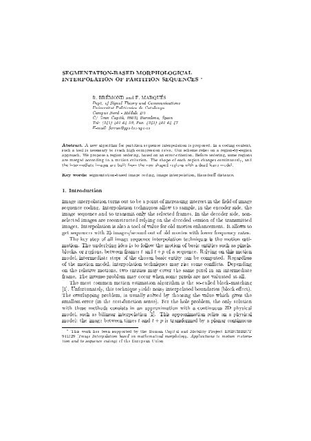
Abstract. A new algorithm for partition sequence <strong>interpolation</strong> is proposed. In a coding context,<br />
such a tool is necessary to reach high compression rates. Our scheme relies on a region-by-region<br />
approach. We propose a region ordering, <strong>based</strong> on an error criterion. Before ordering, some regions<br />
are merged according to a motion criterion. The shape <strong>of</strong> each region changes continuously, and<br />
the intermediate <strong>image</strong>s are built from the new shaped regions with a dead leave model.<br />
Key words: segmentation-<strong>based</strong> <strong>image</strong> coding, <strong>image</strong> <strong>interpolation</strong>, Hausdor distance.<br />
1. Introduction<br />
Image <strong>interpolation</strong> turns out to be a point <strong>of</strong> increasing interest in the eld <strong>of</strong> <strong>image</strong><br />
sequence coding. Interpolation techniques allow to sample, in the encoder side, the<br />
<strong>image</strong> sequence and to transmit only the selected frames. In the decoder side, nonselected<br />
<strong>image</strong>s are reconstructed relying on the decoded version <strong>of</strong> the transmitted<br />
<strong>image</strong>s. Interpolation is also a tool <strong>of</strong> value for old movies enhancement. It allows to<br />
get sequences with 25 <strong>image</strong>s/second out <strong>of</strong> old movies with lower frequency rates.<br />
The key step <strong>of</strong> all <strong>image</strong> sequence <strong>interpolation</strong> techniques is the motion estimation.<br />
The underlying idea is to follow the motion <strong>of</strong> basic entities such as pixels,<br />
blocks, or regions, between frames t and t + p <strong>of</strong> a sequence. Relying on this motion<br />
model, intermediate steps <strong>of</strong> the chosen basic entity can be computed. Regardless<br />
<strong>of</strong> the motion model, <strong>interpolation</strong> techniques may rise some conicts. Depending<br />
on the relative motions, two entities may cover the same pixel in an intermediate<br />
frame. The inverse problem may occur when some pixels are not valuated at all.<br />
The most common motion estimation algorithm is the so-called block-matching<br />
[1]. Unfortunately, thistechnique yields noisy interpolated boundaries (block eect).<br />
The overlapping problem, is usually solved by choosing the value which gives the<br />
smallest error (in the cost-function sense). For the hole problem, the only solution<br />
with these methods consists in an approximation with a continuous 2D physical<br />
model, such as bilinear <strong>interpolation</strong> [1]. This approximation relies on a physical<br />
model: the <strong>image</strong> between times t and t + p is transformed by a planar continuous<br />
This work has been supported by the Human Capital and Mobility Project ERBCHBICT<br />
941329 (Image Interpolation <strong>based</strong> on mathematical morphology. Applications to motion restoration<br />
and to sequence coding) <strong>of</strong> the European Union
2 R. BREMOND AND F. MARQUES<br />
deformation, and this continuity allows to interpolate an uncertainty area with a<br />
smooth continuous function. Unfortunately, real sequences are not the result <strong>of</strong><br />
such continuous transforms.<br />
The development <strong>of</strong> region-<strong>based</strong> methods in many elds <strong>of</strong> <strong>image</strong> processing<br />
makes possible to develop such an approach for sequence <strong>interpolation</strong>. The region<strong>based</strong><br />
approach to<strong>interpolation</strong> uses a segmentation description <strong>of</strong> <strong>image</strong> sequences.<br />
As result <strong>of</strong> the segmentation step, <strong>image</strong>s are split into a set <strong>of</strong> regions forming<br />
a partition. Such regions are characterized by their texture and contours. The<br />
segmentation should put in correspondence regions in successive <strong>image</strong>s by tracking<br />
them through the time domain [4]. Then, each region is interpolated (its shape<br />
and texture separately), and the individual <strong>interpolation</strong>s are combined in order to<br />
build an interpolated <strong>image</strong>. If the segmentation is good enough, each region moves<br />
coherently so that the description <strong>of</strong> the motion <strong>of</strong> each region is more accurate than<br />
with the block-matching.<br />
2. General scheme<br />
I t and I t+p are the partitions (label <strong>image</strong>s) corresponding to the segmentation <strong>of</strong><br />
frames t and t + p <strong>of</strong> a sequence. We propose a general scheme for building the<br />
intermediate partitions I t+1 :::I t+p;1 with no other input data than the two initial<br />
partitions I t and I t+p . Therefore, this <strong>interpolation</strong> technique is independent <strong>of</strong>the<br />
type <strong>of</strong> segmentation process that has been used and, thus, it can be applied to any<br />
segmentation-<strong>based</strong> coding scheme. Let R t (i) bethe region with label i in I t and<br />
R t+p (i) the region with the same label in I t+p .<br />
The proposed scheme copes separately with each region or group <strong>of</strong> regions (concept<br />
<strong>of</strong> meta-region). The scheme can be split into four steps [3]: Region parametrization,<br />
Region ordering, Region <strong>interpolation</strong> and Partition creation.<br />
Region parametrization: the evolution <strong>of</strong> a region from R t (i) to R t+p (i) is<br />
divided into regular motion and shape deformation. These types <strong>of</strong> evolution<br />
are separately modeled. If neighbor regions present similar regular motion, they<br />
are merged into a meta-region. Region parametrization is necessary in order to<br />
have a representation <strong>of</strong> the region that can be easily interpolated.<br />
Region ordering: depth parameters d(i) are computed for each region. They<br />
should correspond to the semantic idea <strong>of</strong> depth: the deepest region should be<br />
in the background, the less deep, in the foreground. By means <strong>of</strong> the region ordering,<br />
possible conicts due to overlapping regions in the interpolated partition<br />
can be solved.<br />
Region <strong>interpolation</strong>: the parameters that characterize the evolution <strong>of</strong> the<br />
region are interpolated, so that a new set <strong>of</strong> interpolated regions is obtained.<br />
Partition creation: interpolated regions are introduced in the interpolated partition<br />
following a dead leave model. Some pixels in the interpolated partition<br />
may not be assigned to any region and, therefore, holes may appear. Hole<br />
conicts are solved with the help <strong>of</strong> a propagation model.<br />
This global scheme is shown in Figure 1. Note that it does not assume any<br />
particular implementation for each step. In the sequel, an eective solution for each<br />
part <strong>of</strong> the algorithm is presented.
MORPHOLOGICAL INTERPOLATION OF PARTITIONS 3<br />
Initial Partitions<br />
Region<br />
Parametrization<br />
Region<br />
Interpolation<br />
Region<br />
Ordering<br />
Partition<br />
Creation<br />
Interpolated Partitions<br />
Fig. 1.<br />
Global object-<strong>based</strong> <strong>interpolation</strong> scheme<br />
3. Region parametrization<br />
3.1. Regular motion estimation<br />
Several models for regular motion can be assumed. The two main types <strong>of</strong> motion in<br />
this application are translation and zooming. The translation <strong>of</strong> the center <strong>of</strong> mass<br />
G(i) gives a rst order approximation <strong>of</strong> the region motion. However, it may lead<br />
to wrong approximations in case <strong>of</strong> fusion or split <strong>of</strong> regions. The zoom factor Z(i),<br />
due to the camera or to the physical motion, can be computed using the surface ratio<br />
between R t (i) and R t+p (i). However, this zoom parameter raises an uncertainty:<br />
It is not clear whether an apparent zoom (computed with this ratio) is due to a<br />
real zoom, or to a mask eect (a region hiding another). To solve this uncertainty,<br />
we propose to classify the possible situations <strong>of</strong> a region. There are three main<br />
possibilities:<br />
1. The region belongs to the foreground. The real zoom corresponds to the surface<br />
ratio, and the translation, to the translation <strong>of</strong> G(i). The corresponding motion<br />
strategy stands on the translation <strong>of</strong> G(i), and on the zoom factor Z(i).<br />
2. The region belongs to the background. The apparent zoom is wrong, because <strong>of</strong><br />
a mask eect. The corresponding motion strategy stands on the translation <strong>of</strong><br />
G(i), without zoom.<br />
3. The region is merged (or split) between frames t and t + p. The apparent<br />
translation is due to a fusion <strong>of</strong> several regions into one, or to the splitting <strong>of</strong><br />
one into several. The motion <strong>of</strong> G(i) does not convey reliable information. The<br />
corresponding careful motion strategy is to stay motionless.<br />
For each region R(i), we compute two motion parameters: the translation ~ T (i)<br />
<strong>of</strong> G(i), and the zoom factor Z(i). Then, a motion error is computed for each <strong>of</strong><br />
the three hypotheses listed above. Depending on the hypothesis which results in the<br />
smallest error, we assign a motion type to the region.<br />
The <strong>interpolation</strong> is sensitive to the choice <strong>of</strong> the cost-function. As we work on<br />
partitions, we cannot use texture information. Let C t (i) be the inner contour <strong>of</strong><br />
R t (i) andD t (i) the distance function to the contour <strong>of</strong> R t (i):
4 R. BREMOND AND F. MARQUES<br />
8p 2 I[D t (i)](p) =D(p C t (i)) (1)<br />
Then, if R t (i) is transformed into Rt+p 0 (i), we use as cost-function the mean<br />
distance between the contour points <strong>of</strong> the two sets. This is computed as:<br />
Cost(R t 7! R 0 t+p )= 1 L<br />
Z<br />
C 0 t+p<br />
D t dL (2)<br />
where L is the length <strong>of</strong> Ct+p 0 (i). The key advantage <strong>of</strong> this function is that it<br />
focuses on the object contour. This property avoids the inuence <strong>of</strong> a surface eect.<br />
Fig. 2 gives an example <strong>of</strong> this eect with the gate on the left. Since the cost<br />
function only relyes on contour information, the <strong>interpolation</strong> manages to follow the<br />
gate motion. This is due to the fact that the cost function is minimum when the<br />
bars <strong>of</strong> I t and I t+p t well. Other cost-functions, such as the intersection distance,<br />
or the Hausdor distance [2], would pay too much attention to the plain portion<br />
<strong>of</strong> the region and a wrong motion may be detected: the gate surface would be<br />
neglectable compared with any motion <strong>of</strong> another part <strong>of</strong> the object. In addition,<br />
recent progresses in mathematical morphology allow to compute D t (i) quickly [7].<br />
Fig. 2.<br />
Importance <strong>of</strong> the contour<br />
3.2. Merging on meta-regions<br />
The merging procedure leads to a high level semantic segmentation. The idea is<br />
to recognize the regions which belong to the same physical object. In this work<br />
a physical object is dened as a set <strong>of</strong> neighbor regions sharing a similar motion.<br />
Therefore, we compare the motion descriptions <strong>of</strong> each pair <strong>of</strong> connected regions,<br />
and merge them if they are similar enough and <strong>of</strong> the same type. This merging step<br />
allows the relaxation <strong>of</strong> the motion description <strong>of</strong> each macro-region.<br />
The merging depends on the motion description. A simple motion model is used,<br />
in order to dene a motion solidarity. The motion model holds a translation vector<br />
~T (i), as well as a zoom qualitative descriptor z(i): for each region R(i), z(i) =True<br />
if there is a true zoom, or z(i) =False if there is no zoom, or a mask eect.<br />
We dene, then, a parametric merging algorithm. A rst negative criterion is<br />
imposed: regions which have dierent types <strong>of</strong> motion cannot be merged. Then we<br />
dene the positive condition <strong>of</strong> merging: If R(i) and R(j) have a common edge,<br />
and are <strong>of</strong> the same type, they belong to the same macro-region if their motion<br />
parameters are similar: k T(i) ~ ; T ~ (j)k
3.3. Shape deformation<br />
MORPHOLOGICAL INTERPOLATION OF PARTITIONS 5<br />
As the previous motion model cannot take into account the real motion <strong>of</strong> complex<br />
objects, a second order model is used. If we compensate the motion <strong>of</strong> R t (i) into<br />
a region Rt+p 0 (i) in frame t + k, and R t+p(i) into R 00<br />
t+k<br />
(i), these two regions do not<br />
t exactly. In order to take into account the continuous deformation from the rst<br />
one to the second one, we use a morphological algorithm developed by F.Meyer [5].<br />
The idea is to compute the geodesic distance from the rst set inside the second<br />
one, then from the second set to the rst one, and to threshold the dierence. The<br />
resulting set corresponds to the shape deformation at the intermediary time t + k.<br />
Two deformation strategies are available. The rst one is to use the algorithm for<br />
every region. The other consists in modifying Meyer's algorithm in order to cope<br />
with several labels at the same time and apply it for each macro-region. Both<br />
techniques have been tested. The main problem with the last strategy is that it may<br />
propagate errors. When the segmentation step creates regions that belong both<br />
to the background and to the foreground (see Fig. 3), labels <strong>of</strong> dierent semantic<br />
objects propagate more easily into each others. We suggest to use this technique<br />
only if it can be ensured that the merging step separates the semantic objects.<br />
Fig. 3.<br />
Ambiguous regions in terms <strong>of</strong> depth<br />
4. Region ordering: Dead leave model<br />
The semantic approach leads to the notion <strong>of</strong> depths. We have classied each region<br />
with a depth value. The interpolated <strong>image</strong> is built by introducing each region with<br />
the following policy: rst the deepest regions (the background), then the upper ones,<br />
up to the toppest region. The nal value <strong>of</strong> a pixel is the label value <strong>of</strong> the last region<br />
which has covered it. It corresponds to the physical model <strong>of</strong> opaque objects moving<br />
and hiding to each other. The importance <strong>of</strong> the error estimation is that it gives<br />
qualitative information about the physical depth. That is, the deeper the region,<br />
the more important the motion estimation error.<br />
The example <strong>of</strong> a synthesis <strong>image</strong> (Fig. 4) gives some evidences <strong>of</strong> this property:<br />
the ball is in the foreground. Since it is not hidden, the motion estimation is correct.<br />
On the contrary, the motion <strong>of</strong> the squares behind the ball cannot be estimated<br />
the same way: even complex motion models would yield bad results, because the<br />
apparent motion does not result from a physical motion but from a masking eect.<br />
The depth value which should be assigned to a macro-region is the highest depth<br />
value from all its regions. The macro-region consists in one physical object, whose<br />
regions have common motion. Then, all the regions <strong>of</strong> the macro-region should have
6 R. BREMOND AND F. MARQUES<br />
Fig. 4.<br />
Synthesis sequence<br />
the same depth. Let us consider a macro-region belonging to the background. It is<br />
made <strong>of</strong> several regions. Some <strong>of</strong> these regions are partially hidden by objects <strong>of</strong> the<br />
foreground, which results in a high value <strong>of</strong> the computed depth. Some other regions<br />
are well estimated because they are not hidden at all. Their computed depth has a<br />
low value. The expected value for the macro-region is the highest one, because the<br />
motion error estimation does not indicate the real depth, but an apparent depth. If<br />
one part <strong>of</strong> the macro-region is behind another region, all the macro-regions should<br />
be considered deeper than this region.<br />
5. Region <strong>interpolation</strong>: Using geodesic distances<br />
A morphological approach to partition deformation <strong>based</strong> on Hausdor distances<br />
has been presented in [5]. In order to compute intermediary steps between two sets,<br />
the idea is to compute the geodesic distance from the rst set to the second one,<br />
then from the second set to the rst one, and to threshold the dierence at any<br />
intermediary time: the resulting set would correspond to the shape deformation at<br />
the chosen intermediate time.<br />
6. Partition creation: Propagation <strong>of</strong> labels<br />
Interpolated regions form the interpolated partition following the ordering obtained<br />
in the Region ordering step. After the dead leave modeling <strong>of</strong> the region positions,<br />
some pixels may not belong to any region. Thus, a propagation model is necessary<br />
in order to ll such holes with their surrounding labels. In the example <strong>of</strong> Fig. 4,<br />
after the dead leave step, there is the following situation:<br />
Fig. 5.<br />
Example <strong>of</strong> <strong>interpolation</strong> before the propagation step.<br />
Fig. 6 shows that the Skiz algorithm gives bad results, since all labels propagate<br />
with the same priority. As the ball is well interpolated, its label should not propagate<br />
through the holes. On the contrary, the squares which are wrongly interpolated<br />
should all contribute to lling the holes.<br />
As for the depth estimation, we rely on an error estimation to propagate each<br />
label in the interpolated <strong>image</strong>s. On Fig. 7, in order to ll the area marked in<br />
black, we would like to compute Err(A) = L 1 and Err(B) = L 2 , so that a label
MORPHOLOGICAL INTERPOLATION OF PARTITIONS 7<br />
Filling the holes: Skiz algorithm.<br />
Filling the holes: Hierarchical propagation.<br />
Fig. 6.<br />
Interpolation <strong>of</strong> a synthesis sequence, skiz algorithm<br />
propagation beginning at time ;L 1 for A and at time ;L 2 for B would cover the<br />
hole exactly with the expected geometry.<br />
L1<br />
L2<br />
A<br />
B<br />
Fig. 7.<br />
Propagation <strong>of</strong> labels<br />
We propose to use as propagation error p(i) the Hausdor distance between the<br />
compensated region R 0 t+k<br />
(i) and R00<br />
t+k<br />
(i). Even if we do not know the exact shape<br />
<strong>of</strong> A 0 and B 0 , the Hausdor distance between the compensated regions at time t + k<br />
approximates the propagation error. This relies on the nature <strong>of</strong> the Hausdor<br />
distance, which may be dened in terms <strong>of</strong> propagation distance.<br />
7. Results<br />
Fig. 8 gives four examples <strong>of</strong> interpolated sequences. The label sequences are computed<br />
with morphological segmentation tools [6]. To present the results, each region<br />
is lled with its mean value in the original <strong>image</strong> I t for the display. In all sequences,<br />
we display one original <strong>image</strong> (on the left) and four interpolated <strong>image</strong>s.<br />
The quality <strong>of</strong> these results is good, in the sense that it is dicult to distinguish<br />
between interpolated and segmented partitions. In addition, the motion continuity<br />
<strong>of</strong> these partitions is well interpolated (see for instance the s<strong>of</strong>t way the man in the<br />
sequence Foreman turns his head, in the rst row <strong>of</strong> Fig. 8).<br />
We have conrmed, in this paper, the interest <strong>of</strong> a region-<strong>based</strong> approach for<br />
<strong>image</strong> sequences <strong>interpolation</strong>. Wehaveintroduced a new algorithm, which performs<br />
the sequence <strong>interpolation</strong> with no other information than the region partition. It<br />
is meant toseparate as much as possible the dierent types <strong>of</strong> data, and to be as<br />
robust as possible. This separation is a consequence <strong>of</strong> the region-<strong>based</strong> approach.
8 R. BREMOND AND F. MARQUES<br />
Fig. 8.<br />
Sequence <strong>interpolation</strong>s<br />
References<br />
1. M. Bierling. Displacement estimation by hierarchical block matching. In Visual Communications<br />
and Image Processing '88, volume 1001, pages 942{951, 1988.<br />
2. D. Huttenlocher, G. Klanderman, and W. Rucklidge. Comparing <strong>image</strong>s using the Hausdor<br />
distance. IEEE Transactions on Pattern Analysis and Machine Intelligence, 15(9):850{863,<br />
September 1993.<br />
3. F. Marques, B. Llorens, and A. Gasull. Interpolation and extrapolation <strong>of</strong> <strong>image</strong> partitions<br />
using Fourier descriptors: Application to segmentation <strong>based</strong> coding schemes. In IEEE International<br />
Conference on Image Processing, volume III, pages 584{587, Washington, DC,<br />
October 1995.<br />
4. F. Marques, M. Pardas, and P. Salembier. Coding-oriented segmentation <strong>of</strong> video sequences. In<br />
L. Torres and M. Kunt, editors, Video Coding: The second generation approach, pages 79{124.<br />
Kluwer Academic Publishers, 1996.<br />
5. F. Meyer. Morphological <strong>interpolation</strong> method for mosaic <strong>image</strong>s. In Proceedings <strong>of</strong> International<br />
Symposium on Mathematical Morphology, May 1996.<br />
6. P. Salembier and M. Pardas. Hierarchical morphological segmentation for <strong>image</strong> sequence<br />
coding. IEEE Transactions on Image Processing, 3(5):639{651, Sept. 1994.<br />
7. P. Soille. Generalized geodesic distances applied to <strong>interpolation</strong> and shape description. In<br />
J. Serra and P. Soille, editors, Mathematical morphology and its applications to <strong>image</strong> processing,<br />
pages 193{200. Kluwer Academic Publishers, 1994.