IPM-4SE 4-Port E1 IP MUX
IPM-4SE 4-Port E1 IP MUX
IPM-4SE 4-Port E1 IP MUX

You also want an ePaper? Increase the reach of your titles
YUMPU automatically turns print PDFs into web optimized ePapers that Google loves.
Chapter 3. Configuration and Operation<br />
3.1 Description<br />
Chapter 3 Configuration and Operation<br />
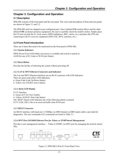
<strong><strong>IP</strong>M</strong>-<strong>4SE</strong> consists of the front panel and the rear panel. The views and description of front and rear panels<br />
are shown in Figure 3.1 and 3.2.<br />
The <strong><strong>IP</strong>M</strong>-<strong>4SE</strong> units are shipped in pre-configured pairs. One is labeled CO (central office) and the other<br />
labeled CPE (customer premises equipment). Be sure to carefully check the model's sticker. Simply place<br />
the CO unit towards the <strong>E1</strong> clock source (SDH multiplexer, BSC, carrier, etc.) and place the CPE unit<br />
connecting to the <strong>E1</strong> recovery equipment (DSU/CSU, BTS, customer, etc.).<br />
3.2 Front Panel Introduction<br />
There are 6 items that need to be mentioned on the front panel of <strong><strong>IP</strong>M</strong>-<strong>4SE</strong>.<br />
3.2.1 System Indicators<br />
PWR (Power Exist LED) Make sure power is available and switch is turned on<br />
ALM (for any of <strong>E1</strong> Links or WAN port Status)<br />
3.2.2 Reset Button<br />
Provides the facility of rebooting the system without powering off.<br />
3.2.3 LAN & MNT Ethernet Connectors and Indicators<br />
The Lan and MNT Ethernet interfaces use an RJ-45 connector with LED indicators<br />
There are green and yellow LED indicators:<br />
• Green Link (Link Up/Down Status)<br />
• Yellow Act (TX/RX Active Status)<br />
3.2.4 Alarm LED Display<br />
<strong>E1</strong>/T1 Interface<br />
• Green ACT (<strong>E1</strong> <strong>Port</strong> Traffic)<br />
• Yellow ALM (<strong>E1</strong> <strong>Port</strong> Link Status)<br />
The "RED" chassis LED indicates one of the following alarms occurred:<br />
<strong>E1</strong>/T1 LOS, AIS, L-bit or no received traffic from WAN port<br />
3.2.5 RS232 Connector<br />
An RS232 interface with baud-rate 115200bps via DB9 (female)-to-DB9 (male) cable is provided for<br />
diagnostics. The user commands (CLI command) are listed in Table 3.1.<br />
3.2.6 MNT <strong>Port</strong> (10/100M Ethernet <strong>Port</strong> for Telnet, or SNMP-based Management)<br />
Provides a user management interface - Telnet or SNMP, via MNT port for managing the local & remote<br />
NEs.<br />
Figure 3.1 <strong><strong>IP</strong>M</strong>-<strong>4SE</strong> 4-<strong>Port</strong> <strong>E1</strong> Front Panel View<br />
13