Gasoline Fuel-Injection System K-Jetronic
Gasoline Fuel-Injection System K-Jetronic
Gasoline Fuel-Injection System K-Jetronic

You also want an ePaper? Increase the reach of your titles
YUMPU automatically turns print PDFs into web optimized ePapers that Google loves.
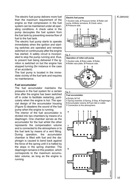
The electric fuel pump delivers more fuel<br />
than the maximum requirement of the<br />
engine so that compression in the fuel<br />
system can be maintained under all operating<br />
conditions. A check valve in the<br />
pump decouples the fuel system from<br />
the fuel tank by preventing reverse flow of<br />
fuel to the fuel tank.<br />
The electric fuel pump starts to operate<br />
immediately when the ignition and starting<br />
switches are operated and remains<br />
switched on continuously after the engine<br />
has started. A safety circuit is incorporated<br />
to stop the pump running and, thus,<br />
to prevent fuel being delivered if the ignition<br />
is switched on but the engine has<br />
stopped turning (for instance in the case<br />
of an accident).<br />
The fuel pump is located in the immediate<br />
vicinity of the fuel tank and requires<br />
no maintenance.<br />
<strong>Fuel</strong> accumulator<br />
The fuel accumulator maintains the<br />
pressure in the fuel system for a certain<br />
time after the engine has been switched<br />
off in order to facilitate restarting, particularly<br />
when the engine is hot. The special<br />
design of the accumulator housing<br />
(Figure 5) deadens the sound of the fuel<br />
pump when the engine is running.<br />
The interior of the fuel accumulator is<br />
divided into two chambers by means of a<br />
diaphragm. One chamber serves as the<br />
accumulator for the fuel whilst the other<br />
represents the compensation volume<br />
and is connected to the atmosphere or to<br />
the fuel tank by means of a vent fitting.<br />
During operation, the accumulator<br />
chamber is filled with fuel and the diaphragm<br />
is caused to bend back against<br />
the force of the spring until it is halted by<br />
the stops in the spring chamber. The<br />
diaphragm remains in this position, which<br />
corresponds to the maximum accumulator<br />
volume, as long as the engine is<br />
running.<br />
Electric fuel pump<br />
1 Suction side, 2 Pressure limiter, 3 Roller-cell<br />
pump, 4 Motor armature, 5 Check valve,<br />
6 Pressure side.<br />
1<br />
Fig. 4<br />
Operation of roller-cell pump<br />
1 Suction side, 2 Rotor plate, 3 Roller,<br />
4 Roller race plate, 5 Pressure side.<br />
Fig. 5<br />
3 4<br />
5<br />
<strong>Fuel</strong> accumulator<br />
a Empty, b Full.<br />
1 Spring chamber, 2 Spring, 3 Stop, 4 Diaphragm,<br />
5 Accumulator volume, 6 <strong>Fuel</strong> inlet or outlet,<br />
7 Connection to the atmosphere.<br />
a<br />
7<br />
b<br />
2<br />
2 3 4<br />
1 5<br />
1 2 3 4 5<br />
6<br />
6<br />
UMK0120-2Y UMK0121-2Y<br />
Fig. 3<br />
K-<strong>Jetronic</strong><br />
UMK1653Y<br />
15