Gasoline Fuel-Injection System K-Jetronic
Gasoline Fuel-Injection System K-Jetronic
Gasoline Fuel-Injection System K-Jetronic

Create successful ePaper yourself
Turn your PDF publications into a flip-book with our unique Google optimized e-Paper software.
Combustion in<br />
the gasoline<br />
engine<br />
Combustion in<br />
the gasoline engine<br />
2<br />
The spark-ignition<br />
or Otto-cycle engine<br />
Operating concept<br />
The spark-ignition or Otto-cycle 1 )<br />
powerplant is an internal-combustion (IC)<br />
engine that relies on an externallygenerated<br />
ignition spark to transform the<br />
chemical energy contained in fuel into<br />
kinetic energy.<br />
Today’s standard spark-ignition engines<br />
employ manifold injection for mixture<br />
formation outside the combustion<br />
chamber. The mixture formation system<br />
produces an air/fuel mixture (based on<br />
gasoline or a gaseous fuel), which is<br />
then drawn into the engine by the suction<br />
generated as the pistons descend. The<br />
future will see increasing application of<br />
systems that inject the fuel directly into the<br />
combustion chamber as an alternate<br />
concept. As the piston rises, it compresses<br />
the mixture in preparation for the timed<br />
ignition process, in which externallygenerated<br />
energy initiates combustion via<br />
the spark plug. The heat released in the<br />
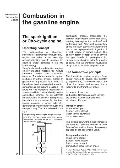
Fig. 1<br />
Reciprocating piston-engine design concept<br />
OT = TDC (Top Dead Center); UT = BDC (Bottom<br />
Dead Center), V h Swept volume, V C Compressed<br />
volume, s Piston stroke.<br />
OT<br />
V h<br />
UT<br />
OT<br />
UT<br />
V C<br />
s<br />
UMM0001E<br />
combustion process pressurizes the<br />
cylinder, propelling the piston back down,<br />
exerting force against the crankshaft and<br />
performing work. After each combustion<br />
stroke the spent gases are expelled from<br />
the cylinder in preparation for ingestion of<br />
a fresh charge of air/fuel mixture. The<br />
primary design concept used to govern<br />
this gas transfer in powerplants for<br />
automotive applications is the four-stroke<br />
principle, with two crankshaft revolutions<br />
being required for each complete cycle.<br />
The four-stroke principle<br />
The four-stroke engine employs flowcontrol<br />
valves to govern gas transfer<br />
(charge control). These valves open and<br />
close the intake and exhaust tracts<br />
leading to and from the cylinder:<br />
1st stroke: Induction,<br />
2nd stroke: Compression and ignition,<br />
3rd stroke: Combustion and work,<br />
4th stroke: Exhaust.<br />
Induction stroke<br />
Intake valve: open,<br />
Exhaust valve: closed,<br />
Piston travel: downward,<br />
Combustion: none.<br />
The piston’s downward motion increases<br />
the cylinder’s effective volume to draw<br />
fresh air/fuel mixture through the passage<br />
exposed by the open intake valve.<br />
Compression stroke<br />
Intake valve: closed,<br />
Exhaust valve: closed,<br />
Piston travel: upward,<br />
Combustion: initial ignition phase.<br />
1 ) After Nikolaus August Otto (1832 –1891), who<br />
unveiled the first four-stroke gas-compression engine<br />
at the Paris World Exhibition in 1876.