SPORT JET INSTALLATION
SPORT JET INSTALLATION
SPORT JET INSTALLATION

You also want an ePaper? Increase the reach of your titles
YUMPU automatically turns print PDFs into web optimized ePapers that Google loves.
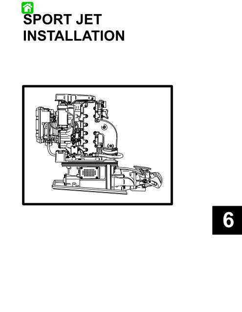
<strong>SPORT</strong> <strong>JET</strong><br />
<strong>INSTALLATION</strong><br />
6<br />
Printed in U.S.A.<br />
6-–1 -<br />
90-823860961 495
Table Of Contents<br />
Page<br />
General Information . . . . . . . . . . . . . . . . . . . . . . . 6-1<br />
Notice to Installer . . . . . . . . . . . . . . . . . . . . . . 6-1<br />
Installation Products . . . . . . . . . . . . . . . . 6-1<br />
Torque Specifications . . . . . . . . . . . . . . . . . . . 6-1<br />
Serial Number Decal Location . . . . . . . . . . . 6-2<br />
Corrosion Protection . . . . . . . . . . . . . . . . . . . 6-2<br />
Installation Requirements . . . . . . . . . . . . . . . . . . 6-2<br />
Battery/Battery Cables . . . . . . . . . . . . . . . . . . 6-2<br />
Boat Construction . . . . . . . . . . . . . . . . . . . . . . 6-3<br />
Engine Compartment Ventilation . . . . . . . . . 6-3<br />
Exhaust System . . . . . . . . . . . . . . . . . . . . . . . 6-3<br />
Fuel Delivery System . . . . . . . . . . . . . . . . . . . 6-3<br />
Instrumentation . . . . . . . . . . . . . . . . . . . . . . . . 6-4<br />
Instrumentation Wiring Diagram . . . . . . . . . . 6-5<br />
Impeller Selection . . . . . . . . . . . . . . . . . . . . . . 6-6<br />
Remote Control and Cables . . . . . . . . . . . . . 6-6<br />
Steering Helm and Cable . . . . . . . . . . . . . . . 6-6<br />
Page<br />
Sport Jet Hull Dimensions . . . . . . . . . . . . . . . . . . 6-7<br />
Installing Jet Pump . . . . . . . . . . . . . . . . . . . . . . . . 6-9<br />
Hull Cutout . . . . . . . . . . . . . . . . . . . . . . . . . . . . 6-9<br />
Cutout thickness . . . . . . . . . . . . . . . . . . . . 6-9<br />
Steering Cable Adjustment . . . . . . . . . . . . . 6-10<br />
Shift Cable Adjustment . . . . . . . . . . . . . . . . 6-12<br />
Bilge Siphon Feature . . . . . . . . . . . . . . . . . . . . . 6-14<br />
Installing Bilge Siphon . . . . . . . . . . . . . . . . . 6-14<br />
Installing Powerhead . . . . . . . . . . . . . . . . . . . . . 6-15<br />
Throttle Cable Adjustment . . . . . . . . . . . . . . 6-16<br />
Battery Connection . . . . . . . . . . . . . . . . . . . . 6-16<br />
Oil Injection System . . . . . . . . . . . . . . . . . . . 6-17<br />
Check Oil Pump Adjustment . . . . . . . . . . . . 6-17<br />
Ride Plate Adjustment . . . . . . . . . . . . . . . . . . . . 6-18<br />
Pre-delivery Inspection . . . . . . . . . . . . . . . . . . . . 6-19<br />
6-0 <strong>SPORT</strong> <strong>JET</strong> <strong>INSTALLATION</strong><br />
90-831996R1 JUNE 1996
General Information<br />
Notice to Installer<br />
Throughout this publication, “Warnings” and “Cautions”<br />
(accompanied by the International Hazard<br />
Symbol ! ) are used to alert the installer to special<br />
instructions concerning a particular service or operation<br />
that may be hazardous if performed incorrectly or<br />
carelessly. –– Observe Them<br />
Carefully!<br />
These “Safety Alerts,” alone, cannot eliminate the<br />
hazards that they signal. Strict compliance to these<br />
special instructions when performing the service,<br />
plus “common sense” operation, are major accident<br />
prevention measures.<br />
! WARNING<br />
Hazards or unsafe practices which COULD result<br />
in severe personal injury or death.<br />
! CAUTION<br />
Hazards or unsafe practices which could result in<br />
minor personal injury or product or property<br />
damage.<br />
IMPORTANT: Indicates information or instructions<br />
that are necessary for proper installation<br />
and/or operation.<br />
This installation manual has been written and published<br />
by the service department of Mercury Marine<br />
to aid installers when installing the products described<br />
herein.<br />
It is assumed that these personnel are familiar with<br />
the installation procedures of these products, or like<br />
or similar products manufactured and marketed by<br />
Mercury Marine. Also, that they have been trained in<br />
the recommended installation procedures of these<br />
products which includes the use of mechanics’ common<br />
hand tools and the special Mercury Marine or<br />
recommended tools from other suppliers.<br />
We could not possibly know of and advise the marine<br />
trade of all conceivable procedures by which an installation<br />
might be performed and of the possible hazards<br />
and/or results of each method. We have not undertaken<br />
any such wide evaluation. Therefore,<br />
anyone who uses an installation procedure and/or<br />
tool, which is not recommended by the manufacturer,<br />
first must completely satisfy himself that neither his<br />
nor the product’s safety will be endangered by the installation<br />
procedure selected.<br />
All information, illustrations, and specifications contained<br />
in this manual are based on the latest product<br />
information available at time of publication. As required,<br />
revisions to this manual will be sent to all OEM<br />
boat companies.<br />
<strong>INSTALLATION</strong> PRODUCTS<br />
Loctite “271” 92-823089--1<br />
Quicksilver Anti-Corrosion<br />
Grease 92-78376A6<br />
Liquid Neoprene 92-25711--2<br />
Dielectric Grease 92-823506--1<br />
Perfect Seal 92-34227--1<br />
Torque Specifications<br />
NOTE: Tighten all fasteners, not listed, securely.<br />
Exhaust Bellows Clamps 50 lb. in.<br />
(5.6 N·m)<br />
Shift Cable Swivel Screws 50 lb. in.<br />
(5.6 N·m)<br />
Shift Cable Mounting<br />
Bracket Screws 50 lb. in.<br />
(5.6 N·m)<br />
8 mm Fasteners<br />
(Powerhead to Pump)<br />
10 mm Fasteners<br />
(Powerhead to Pump)<br />
Cooling Waterline Nut<br />
Steering Cable Mounting<br />
Bracket Screws<br />
Reverse Stop Screw<br />
Forward Stop Screw<br />
Ride Plate-to-Pump Screws<br />
Drive Housing Cover to Drive<br />
Housing fasteners<br />
20 lb. ft.<br />
(27 N·m)<br />
35 lb. ft.<br />
(47 N·m)<br />
Snug with Wrench,<br />
Then Tighten One<br />
Addition Flat<br />
(60 degrees)<br />
200 lb. in.<br />
(23 N·m)<br />
120 lb. in.<br />
(14 N·m)<br />
120 lb. in.<br />
(14 N·m)<br />
75 lb. in.<br />
(8.5 N·m)<br />
35 lb. ft.<br />
(47 N·m)<br />
90-831996R1 JUNE 1996 <strong>SPORT</strong> <strong>JET</strong> <strong>INSTALLATION</strong><br />
6-1
Serial Number Decal Location<br />
A serial number decal is located on the flywheel cover.<br />
OGXXXXXX<br />
IMPORTANT: The Pump Unit Serial Number sticker<br />
must be taken out of the envelope affixed to the<br />
pump unit and applied to the flywheel cover decal.<br />
The engine serial number and pump serial number<br />
are different and unique. The engine serial number is<br />
located aft of the flywheel cover. The pump unit serial<br />
number is stamped in a plug located above the shift<br />
cable hole on the port side of the pump housing.<br />
a - Engine Serial Number<br />
b - Model Year<br />
c - Year Manufactured<br />
e<br />
a<br />
d<br />
OGXXXXXX<br />
19XX<br />
XX<br />
b<br />
c<br />
d - Certified Europe<br />
e - Pump Unit Serial Number<br />
conditions. See the Operator’s Manual for location of<br />
anodes.<br />
Installation Requirements<br />
IMPORTANT: The Sport Jet is considered an<br />
INBOARD engine. The boat it is installed in must<br />
meet industry standards (ABYC, NMMA, etc.),<br />
federal standards and Coast Guard regulations<br />
for INBOARD engine installations<br />
Battery/Battery Cables<br />
IMPORTANT: Boating industry standards (ABYC,<br />
NMMA, etc.), federal standards and Coast Guard<br />
regulations must be adhered to when installing<br />
battery. Be sure battery cable installation meets<br />
the pull test requirements and that positive battery<br />
terminal is properly insulated in accordance<br />
with regulations.<br />
IMPORTANT: Engine electrical system is negative<br />
(–) ground. It is recommended (required in some<br />
states) that battery be installed in an enclosed<br />
case. Refer to regulations for your area.<br />
1. Select a battery that meets all of the following<br />
specifications:<br />
a. 12-volt marine type.<br />
b. 670 Marine Cranking Amps (MCA) or<br />
520 Cold Cranking Amps (CCA).<br />
c. Reserve capacity rating of at least 100 minutes.<br />
2. Select proper size positive (+) and negative (–)<br />
battery cables using chart. Battery should be located<br />
as close to engine as possible.<br />
IMPORTANT: Terminals must be soldered to<br />
cable ends to ensure good electrical contact. Use<br />
electrical grade (resin flux) solder only. Do not<br />
use acid flux solder, as it may cause corrosion<br />
and a subsequent failure.<br />
Cable Length<br />
Cable Gauge<br />
Up to 3-1/2 ft. (1.1 m) 4 (25mm 2 )<br />
3-1/2 - 6 ft. (1.1-1.8 m) 2 (35mm 2 )<br />
6 - 7-1/2 ft. (1.8-2.3 m) 1 (50mm 2 )<br />
7-1/2 - 9-1/2 ft. (2.3-2.9 m) 0 (50mm 2 )<br />
9-1/2 - 12 ft. (2.9-3.7 m) 00 (70mm 2 )<br />
12 - 15 ft. (3.7- 4.6 m) 000 (95mm 2 )<br />
15 - 19 ft. (4.6 - 5.8 m) 0000(120mm 2 )<br />
Corrosion Protection<br />
This power package is equipped with anodes to help<br />
protect it from galvanic corrosion under moderate<br />
6-2 <strong>SPORT</strong> <strong>JET</strong> <strong>INSTALLATION</strong><br />
90-831996R1 JUNE 1996
Boat Construction<br />
IMPORTANT: All applicable Coast Guard regulations<br />
for INBOARD engines must be complied<br />
with, when constructing engine compartment.<br />
Care must be exercised in the design and construction<br />
of the engine compartment. Seams must be located<br />
so that any rain water or splash, which may leak<br />
through the seams, is directed away from the engine<br />
and carburetor cover. Also, the passenger compartment<br />
drainage system should not be routed directly<br />
to the engine compartment. Water that runs on or is<br />
splashed in the carburetor cover may enter the<br />
engine and cause serious damage to internal engine<br />
parts.<br />
IMPORTANT: Mercury Marine will not honor any<br />
warranty claim for engine damage as a result of<br />
water entry.<br />
Engine Compartment Ventilation<br />
Engine compartment must be designed to provide a<br />
sufficient volume of air for engine breathing and also<br />
must vent off any fumes in engine compartment in<br />
accordance with industry standards (ABYC, NMMA,<br />
etc.), federal standards and Coast Guard regulations<br />
for inboard engines. Pressure differential (outside engine<br />
compartment versus inside engine compartment)<br />
should not exceed 2 in. (51mm) of water (measured<br />
with a manometer) at maximum air flow rate.<br />
Engine Compartment Specifications<br />
Model<br />
90/95<br />
HP<br />
120<br />
HP<br />
Engine Air Requirements<br />
at Wide Open<br />
Throttle<br />
230 ft. 3 /min.<br />
(0.109m 3 /sec.)<br />
304 ft. 3 /min.<br />
(0.143 m 3 /sec.)<br />
Physical Engine<br />
Volume*<br />
0.60 ft. 3<br />
(17 L)<br />
0.67 ft. 3<br />
(19 L)<br />
* Physical engine volume is used in flotation calculations and is<br />
representative of the amount of flotation the engine provides.<br />
For serviceability, it is recommended that an additional<br />
6 inches minimum (152 mm) (per side) of clearance<br />
be allowed between powerhead and engine<br />
compartment walls.<br />
Exhaust System<br />
IMPORTANT: It is the responsibility of the boat<br />
manufacturer, or installing dealer, to properly<br />
locate the engine. Improper installation may<br />
allow water to enter the exhaust manifold and<br />
combustion chambers and severely damage the<br />
engine. Damage caused by water in the engine<br />
will not be covered by Mercury Marine Limited<br />
Warranty, unless this damage is the result of<br />
defective part(s).<br />
The engine must be properly located to ensure that<br />
water will not enter the engine through the exhaust<br />
system. Determine the correct engine height by taking<br />
measurements (a) and (b), with boat at rest in the<br />
water and maximum load aboard. Subtract (b) from<br />
(a) to find (c). If (c) is less than specified in chart, boat<br />
construction must be altered to properly lower waterline<br />
relative to exhaust elbow.<br />
a - From Waterline to Top of Transom<br />
b - From Highest Point on Exhaust Elbow to Top of Transom<br />
c - (a) minus (b) = (c)<br />
d - Waterline at Rest (at Maximum Load)<br />
Model<br />
90/95/120<br />
HP<br />
b<br />
c<br />
c = (a) minus (b)<br />
Fuel Delivery System<br />
(c) must be 7.5 in. (330 mm) or<br />
more.<br />
! WARNING<br />
Boating standards (NMMA, ABYC, etc.), federal<br />
standards and Coast Guard regulations for<br />
INBOARD engines must be adhered to when installing<br />
fuel delivery system.<br />
! CAUTION<br />
Remove plastic plug from fuel inlet fitting. Attach<br />
fuel line to fuel fitting with hose clamp. Inspect for<br />
fuel leaks.<br />
1. Fuel tank should be mounted below carburetor(s)<br />
level (if possible) or gravity feed may cause carburetor<br />
fuel inlet needle(s) to unseat, and flooding<br />
may result.<br />
a<br />
d<br />
90-831996R1 JUNE 1996 <strong>SPORT</strong> <strong>JET</strong> <strong>INSTALLATION</strong><br />
6-3
2. Fuel pickup should be at least 1 in. (25mm) from<br />
the bottom of the fuel tank to prevent picking up<br />
impurities.<br />
3. Fuel lines used must be Coast Guard approved<br />
(USCG type A1), fittings and lines must not be<br />
smaller than 5/16 in. (8mm) I.D.<br />
4. On installations requiring long lines or numerous<br />
fittings, larger size lines should be used.<br />
5. Fuel line should be installed free of stress and<br />
firmly secured to prevent vibration and/or chafing.<br />
6. Sharp bends in fuel line should be avoided.<br />
7. A flexible fuel line must be used to connect fuel<br />
line to engine fuel pump to absorb deflection<br />
when engine is running.<br />
8. A primer bulb is not necessary with this application.<br />
If a primer bulb is used, it must be Coast<br />
Guard approved for inboard engine applications.<br />
a<br />
We recommend the use of Quicksilver Instrumentation<br />
and Wiring Harness(es). Refer to “Quicksilver<br />
Accessories Guide” for selection.<br />
If other than Quicksilver electrical accessories are to<br />
be used, it is good practice to use waterproof ignition<br />
components (ignition switch, lanyard stop switch,<br />
etc.). A typical jet boat of this nature will see water<br />
splashed on these components. Therefore, precautions<br />
must be taken to avoid ignition failure due to<br />
shorting out of ignition components.<br />
! WARNING<br />
Sudden stopping of engine (shorting ignition<br />
components) while boat is underway will cause<br />
loss of steering control due to loss of thrust. This<br />
loss of steering control may cause property damage,<br />
personal injury or death.<br />
A warning horn must be incorporated in the wiring<br />
harness (see wiring diagram) to alert the user of an<br />
overheat or low oil condition.<br />
IMPORTANT: If a warning horn system is not<br />
installed by the boat manufacturer, Mercury<br />
Marine will not honor any warranty claims for<br />
engine damage as a result of overheating or lack<br />
of engine oil.<br />
Route instrumentation wiring harness back to engine,<br />
making sure that harness does not rub or get pinched.<br />
If an extension harness is required, be sure to secure<br />
connection properly. Fasten harness(es) to boat at<br />
least every 18 in. (460 mm), using appropriate fasteners.<br />
a - Fuel Inlet<br />
Instrumentation<br />
! CAUTION<br />
If a fused accessory panel is to be used, it is recommended<br />
that a separate circuit (properly<br />
fused) be used from the battery to the fuse panel<br />
with sufficient wire size to handle the intended<br />
current load.<br />
NOTE: The charging system on these engines is<br />
capable of producing 9 amps maximum charge at<br />
3500 RPM (4.5 amps minimum at 1000 RPM). The<br />
electrical load of the boat should not exceed this<br />
capacity. If loads higher than the capacity of the<br />
charging system are anticipated, refer to “Quicksilver<br />
Accessory Guide” for a high output alternator.<br />
6-4 <strong>SPORT</strong> <strong>JET</strong> <strong>INSTALLATION</strong><br />
90-831996R1 JUNE 1996
Instrumentation Wiring Diagram<br />
QUICKSILVER INSTRUMENTATION, TYPICAL <strong>INSTALLATION</strong> SHOWN<br />
REFER TO GAUGE MANUFACTURER’S INSTRUCTIONS FOR SPECIFIC CONNECTIONS.<br />
i<br />
Temperature Sender<br />
(Included With Gauge)<br />
a - Temperature Gauge<br />
b - Key Switch<br />
c - Tachometer Gauge<br />
d - Emergency Stop Switch<br />
e - Tachometer Harness (P/N 84-86396A8) (Not Included<br />
With Key/Choke Harness Kit)<br />
f - Connect Wires Together With Screw and Hex Nut (2<br />
Places) Apply Quicksilver Liquid Neoprene to Connections<br />
and Slide Rubber Sleeve Over Each Connection.<br />
g - To Neutral Start Safety Switch In Remote Control Box<br />
h - Speedometer Gauge<br />
i - Overheat/low oil horn<br />
P<br />
T<br />
Liquid Neoprene (92-25711--2)<br />
Dielectric Grease (92-823506--1)<br />
90-831996R1 JUNE 1996 <strong>SPORT</strong> <strong>JET</strong> <strong>INSTALLATION</strong><br />
6-5
Impeller Selection<br />
IMPORTANT: Installed impeller must allow engine<br />
to run in its specified maximum wide-openthrottle<br />
RPM range.<br />
The jet drive comes equipped with a standard stainless<br />
steel impeller which allows the engine to operate<br />
in its specified operating range.<br />
If a different impeller is installed in place of the standard<br />
impeller, it is the responsibility of the installer to<br />
ensure engine RPM remains in specified range. Specified<br />
engine WOT RPM range is listed in “Operation<br />
and Maintenance Manual” attached to the engine.<br />
Remote Control and Cables<br />
To ensure proper shift and throttle operation, we recommend<br />
the use of a Morse MV2 “special” remote<br />
control. This control has been qualified by Mercury to<br />
be used for the Sport Jet and provides the following<br />
features:<br />
• Start-in-Neutral Protection<br />
• Fast Idle Speed Limit at 1800 RPM<br />
• Increased Strength to Compensate for Higher<br />
Shift Loads Transmitted Through the Shift<br />
Cable<br />
• Shift Cable Travel of 2.50 inches (63.5 mm)<br />
If a control other than the Morse MV2 “special” remote<br />
control is to be used, the control must meet the above<br />
criteria as well as be approved by Mercury Marine<br />
Engineering.<br />
Contact Mercury Marine Distribution for availability of<br />
this control box.<br />
SHIFT CABLE<br />
The shift cable end (at the pump) is submersed in<br />
water. It should be sealed against water intrusion,<br />
protected against corrosion and be able to withstand<br />
the shift loads imparted on it by the reverse gate.<br />
Follow shift cable adjustment procedure for proper<br />
adjustment.<br />
THROTTLE CABLE<br />
The throttle cable must have one end compatible with<br />
the control box. The other end must have Mercury<br />
style connectors.<br />
Follow throttle cable adjustment procedures for<br />
proper adjustment.<br />
The steering helm must limit steering cable travel to<br />
3.50 ± .10 inches (88.9 ± 2.5 mm).<br />
! WARNING<br />
Failure to limit steering cable travel at the helm<br />
could pre-load the cable resulting in premature<br />
failure of a steering component causing loss of<br />
steering. This loss of steering could cause property<br />
damage, personal injury or death.<br />
STEERING CABLE<br />
The steering cable to be used must meet the following<br />
criteria.<br />
• Allow for a minimum of 3.75 inches (95.3 mm)<br />
of travel.<br />
• Cable end at pump must allow for a shouldered<br />
thru-bolt to connect the cable to the<br />
steering arm.<br />
• A means of attaching and locking the cable to<br />
the steering cable bracket (provided).<br />
• Protected against water intrusion and/or corrosion<br />
as the cable end (at the pump) is submersed<br />
in water with the boat at rest.<br />
A locking tab is provided by Mercury to be used with<br />
a cable having threads and locknuts located 11.31<br />
inches (287 mm) from cable end at pump with cable<br />
at center of travel.<br />
Steering Helm and Cable<br />
STEERING HELM<br />
6-6 <strong>SPORT</strong> <strong>JET</strong> <strong>INSTALLATION</strong><br />
90-831996R1 JUNE 1996
Sport Jet Hull Dimensions<br />
90/95/120<br />
HULL OPENING CUT OUT<br />
The pump to powerhead opening in the hull is the<br />
most important factor to consider in a Sport Jet installation.<br />
There are three areas of concern:<br />
1. Location (a) of the pump to powerhead hull cut out<br />
relative to the boat bottom for proper ride plate<br />
seal fit.<br />
2. Dimensional control of the cutout - corner radii<br />
(b), straightness (c) and size (d) for proper grommet<br />
installation, and corner radii (e) for ride plate<br />
seal fit.<br />
3. Flatness and thickness of the area around the hull<br />
cut out for proper grommet sealing (see drawing<br />
on next page ).<br />
Tunnel Dimensions (in inches)<br />
1 1/16 +/– 1/16<br />
e<br />
12 1/8 +/– 1/16<br />
c<br />
d<br />
7 1/16 +/– 1/16<br />
b<br />
3/4 +/– 1/16<br />
14 11/16 +/– 1/16<br />
16 1/4 +/– 1/16<br />
c<br />
d<br />
14 5/16 +/– 1/16<br />
a<br />
2 9/16 +/– 1/16<br />
3 13/16 +/– 1/16<br />
3 5/8 +/– 1/16<br />
a<br />
a<br />
a - Location<br />
b and e - Corner Radii<br />
c and d - Size and Straightness<br />
90-831996R1 JUNE 1996 <strong>SPORT</strong> <strong>JET</strong> <strong>INSTALLATION</strong><br />
6-7
METHODS OF CONTROLLING LOCATION AND SIZE<br />
If the tunnel area in the plug is correct, the boat bottom<br />
mold should repeat and reproduce the tunnel<br />
area which will aid the cut out process.<br />
A reference area for the cut out can be produced on<br />
the plug and bottom mold as a raised area or a cutting<br />
guide.<br />
Location pins (a) that would project into the internal<br />
hull area could simplify the cut out process.<br />
These location pin holes could allow the use of a 1 1/2<br />
inch diameter hole saw to cut the four corner radii and<br />
use of a reciprocating saw or router template to connect<br />
the four holes.<br />
CHECKING MOUNTING FLANGE THICKNESS AND<br />
FLATNESS<br />
Use a flat plate that will contact the flange at the reference<br />
points (b) and a .030 in. feeler gauge to check<br />
flatness.<br />
Additional sanding and/ or resin/ filler may be required<br />
to maintain the flatness specification.<br />
A simple slotted go/ no go gauge (c) will check the<br />
flange thickness.<br />
b<br />
Recommended Flange Flatness: .030 Inch<br />
Maximum Between Reference Points<br />
A<br />
a<br />
1 1/2 Inch Dia. Hole Saw<br />
a<br />
A<br />
1/2<br />
a<br />
a<br />
1/2<br />
1/2<br />
1/2<br />
1 Inch Minimum Flange Width<br />
Mounting Flange Thickness<br />
Specifications<br />
Section A-A<br />
1/4” +0.050<br />
–0.030<br />
3/8” +0.050<br />
a - Location Pins in Hull Mold<br />
–0.030<br />
b - Flange Flatness Specification<br />
c - Go – No Go Gauge for Thickness 1/2” +0.070<br />
–0.030<br />
Max. Size<br />
Use Grommet P/N:<br />
25-820663-250<br />
25-820663-375<br />
25-820663-500<br />
GO<br />
NO<br />
GO<br />
Min. Size<br />
c<br />
6-8 <strong>SPORT</strong> <strong>JET</strong> <strong>INSTALLATION</strong><br />
90-831996R1 JUNE 1996
Installing Jet Pump<br />
Hull Cutout<br />
! CAUTION<br />
The hull cutout dimensions are critical for proper<br />
sealing between Jet Pump and boat. Measure cutout<br />
thickness and overall dimensions before attempting<br />
a Jet Pump installation.<br />
1. Install tunnel grommet (a) in cut-out of boat.<br />
Three different size grommets are available depending<br />
on cutout thickness.<br />
2. Spray soapy water on tunnel grommet, both side<br />
foam exhaust seals (a) ride plate seal (b) and<br />
sides of boat tunnel.<br />
b<br />
a<br />
a<br />
Bottom View<br />
Use Grommet P/N:<br />
1/4” +0.050<br />
–0.030<br />
3/8” +0.050<br />
–0.030<br />
1/2” +0.070<br />
–0.030<br />
25-820663-250<br />
25-820663-375<br />
25-820663-500<br />
a - Side Foam Exhaust Seals (One Each Side)<br />
b - Ride Plate Seal<br />
3. Route steering cable (b) through port side hole (a)<br />
in flange of pump housing. Route shift cable (d)<br />
through starboard side hole (c) in flange of pump<br />
housing.<br />
ÀÀ ÀÀ ÀÀ<br />
ÀÀ<br />
ÀÀ<br />
ÀÀ ÀÀ ÀÀ<br />
ÀÀ<br />
ÀÀ<br />
CUTOUT THICKNESS<br />
a<br />
c<br />
b<br />
d<br />
NOTE: When installing pump in tunnel, be sure<br />
cables are below flange on pump to prevent pinching<br />
of cables between pump and boat.<br />
90-831996R1 JUNE 1996 <strong>SPORT</strong> <strong>JET</strong> <strong>INSTALLATION</strong><br />
6-9
4. Install jet pump (a) by pushing unit through opening<br />
in tunnel grommet (b). Ride plate seal should<br />
fit snug in boat tunnel without any gaps along perimeter.<br />
Steering Cable Adjustment<br />
1. Loosen steering cable thru-hull fitting. Pull steering<br />
cable out as far as possible to allow enough<br />
room to work. Attach steering cable mounting<br />
bracket (b) to cable (d) using two (2) nuts (a) and<br />
one tab washer (e). Position bracket so that when<br />
nuts are tighten securely, 1/16 to 1/8 in. of cable<br />
threads are exposed. This is the preliminary<br />
coarse adjustment. Tighten nuts securely, bend<br />
washer against flats of each nut.<br />
a<br />
d<br />
e<br />
b<br />
a<br />
a - Jet Pump<br />
b - Tunnel Grommet<br />
5. Install gasket and cover (d) on jet pump. Align<br />
holes in cover with locating pins in housing and<br />
secure with four (4) M10 x 1.5 nuts (c).<br />
c<br />
2. Apply Loctite 271 (red) to three (3) screws (c) and<br />
attach bracket (b) to pump housing. Torque<br />
screws to 200 lb. in. (23 N·m).<br />
c<br />
b<br />
NOTE: Before torquing fasteners, check side exhaust<br />
seals and ride plate seal for proper fit in tunnel.<br />
6. Torque housing cover nuts (c) to 35 lb. ft. (47<br />
N·m).<br />
d<br />
a<br />
c<br />
b<br />
d<br />
a - Steering Cable Attaching Nuts and Tab Washer<br />
b - Mounting Bracket<br />
c - Mounting Bracket Screws (3)<br />
d - Shift cable<br />
6-10 <strong>SPORT</strong> <strong>JET</strong> <strong>INSTALLATION</strong><br />
90-831996R1 JUNE 1996
3. Center rudder assembly on nozzle.<br />
4. Thread jam nut (a) and cable end adaptor (b) on<br />
steering cable.<br />
7. If additional adjustment is required, the steering<br />
cable can be re-adjusted as described in step 1.,<br />
preceding. Be sure to tighten nuts and bend tab<br />
washer after adjustment is made.<br />
8. Attach steering cable to steering arm with bolt (a)<br />
and locknut (b).<br />
b<br />
b<br />
a<br />
a<br />
9. Tighten steering cable thru-hull fitting (a) from inside<br />
boat to prevent any leaks.<br />
5. Center steering wheel by turning wheel lock to<br />
lock and positioning wheel midway between<br />
locks.<br />
6. Adjust cable end adaptor (a) until thru-hole in<br />
adaptor lines up with threaded hole in steering<br />
arm (b). This is the steering cable fine adjustment.<br />
Cable end adaptor MUST be installed on steering<br />
cable a minimum of nine (9) turns. Tighten jam nut<br />
against adaptor.<br />
b<br />
a<br />
a<br />
a - Steering Cable Thru-Hull Fitting<br />
! WARNING<br />
Failure to install cable end adaptor on steering<br />
cable a minimum of nine (9) turns could result in<br />
loss of steering control of boat, personal injury,<br />
or death.<br />
90-831996R1 JUNE 1996 <strong>SPORT</strong> <strong>JET</strong> <strong>INSTALLATION</strong><br />
6-11
Shift Cable Adjustment<br />
IMPORTANT: The shift cable MUST BE properly<br />
adjusted. The shift cable is adjusted so that the<br />
reverse gate is not pre-loaded against the stop in<br />
forward or reverse. Pre-load in either position will<br />
cause failure of the stop and/or premature wear of<br />
the shift cable/control box components.<br />
1. Install shift cable end (b) in slot of reverse gate (a)<br />
and secure with clevis pin (c), washer (d), and cotter<br />
pin (e). Bend over ends of cotter pin.<br />
2. Mount shift cable adjustment bracket (a) to stator<br />
with screws (b) and locking tab (c). Do not tighten<br />
screws at this time.<br />
a<br />
c<br />
b<br />
e<br />
d<br />
a<br />
c<br />
b<br />
a-Reverse Gate Slot<br />
b-Shift Cable End<br />
c-Clevis Pin<br />
d-Washer<br />
e-Cotter Pin<br />
3. Install shift cable and secure with clamp (a), tab<br />
lock (b), and two (2) screws (c) making sure that<br />
thru-hole (e) in swivel is located below cable. The<br />
radius portion of the tab lock (b) must face towards<br />
the reverse gate. Torque screws to 50 lb.<br />
in. (5.6 N·m). Bend tabs (d) over flats of screw<br />
heads.<br />
a<br />
d<br />
e<br />
b<br />
c<br />
d<br />
6-12 <strong>SPORT</strong> <strong>JET</strong> <strong>INSTALLATION</strong><br />
90-831996R1 JUNE 1996
4. Shift remote control to forward.<br />
5. Position reverse gate (a) with cupped edge at or<br />
slightly above rudder I.D. (b).<br />
a<br />
7. Adjust shift cable bracket (c) so that reverse gate<br />
touches forward stop but does not pre-load shift<br />
cable. Torque bracket screws (d) to 50 lb. in. (5.6<br />
N·m). Bend locking tabs against flats of screw<br />
head.<br />
c<br />
b<br />
d<br />
a - Reverse Gate Cupped Edge<br />
b - Rudder I.D.<br />
6. Loosen forward stop screw (a) and rotate forward<br />
stop (located on port side of nozzle) clockwise until<br />
it just contacts reverse gate (b). Torque forward<br />
stop screw to 120 lb. in. (14 N·m).<br />
IMPORTANT: Inspect position of reverse gate in<br />
forward gear, reverse gate must not interfere with<br />
water flow coming out of rudder.<br />
8. Shift remote control to reverse.<br />
9. Loosen reverse stop screw (e) and rotate stop (located<br />
on starboard side of nozzle) clockwise until<br />
it just contacts reverse gate. Torque screw to 120<br />
lb. in. (14 N·m).<br />
b<br />
a<br />
IMPORTANT: Forward stop must be correctly adjusted<br />
so that reverse gate does not interfere with<br />
water flow coming out of rudder.<br />
IMPORTANT: Check that upper edge of reverse<br />
gate does not interfere with steering arm attaching<br />
screws throughout steering range when<br />
reverse gate is in the forward position.<br />
e<br />
90-831996R1 JUNE 1996 <strong>SPORT</strong> <strong>JET</strong> <strong>INSTALLATION</strong><br />
6-13
10. Check shift cable/reverse gate adjustments as<br />
follows:<br />
a. Shift control box to forward gear.<br />
b. Pivot reverse gate up and down using light<br />
pressure. Gate should be able to move within<br />
the clearance between the shift cable end and<br />
clevis pin (a). If not, gate is pre-loaded against<br />
the stop. Repeat steps 2 through 11.<br />
11. Tighten shift cable thru-hull fitting (a) from inside<br />
boat to prevent any leaks.<br />
a<br />
a<br />
Bilge Siphon Feature<br />
The Sport Jet incorporates an automatic bilge siphoning<br />
feature. The bilge siphon is working whenever the<br />
engine is running. Two hoses are attached to the jet<br />
pump nozzle. The hoses are routed to the engine<br />
compartment and placed on each side of the jet tunnel.<br />
Water exiting the nozzle creates a suction or vacuum<br />
in the hoses creating the bilge siphon.<br />
Installing Bilge Siphon<br />
1. Attach the two hoses supplied to the hose barbs<br />
located at the center rear of the drive housing cover.<br />
c. Shift control box to reverse and repeat step b.<br />
(above).<br />
NOTE: In neutral, the reverse gate covers approximately<br />
3/4 of the rudder opening.<br />
IMPORTANT: After any adjustments are made<br />
shift control box through entire range and recheck<br />
reverse gate clearance to rudder (step 5<br />
preceding) and reverse gate stops (step 11 ).<br />
NOTE: Be sure shift cable swivel does not interfere<br />
with stator mounting bolt (b) through-out entire shift<br />
range.<br />
2. Attach the hoses to the transom with the hose<br />
clips supplied.<br />
IMPORTANT:<br />
3. Position each siphon break (a) a minimum of 8<br />
in. (203 mm) above pump cover.<br />
a<br />
8 in. minimum<br />
(203 mm)<br />
b<br />
6-14 <strong>SPORT</strong> <strong>JET</strong> <strong>INSTALLATION</strong><br />
90-831996R1 JUNE 1996
Installing Powerhead<br />
1. Remove exhaust bellows (a) from exhaust elbow<br />
and install on drive housing cover (b).<br />
2. Check that o-rings (c) are in drive housing cover<br />
(b), and slinger (d) is on drive shaft.<br />
7. Secure powerhead to drive housing cover with<br />
four (4) M10 x1.5 (a) and four (4) M8 x 1.25 nuts.<br />
(b) Torque fasteners following the torque sequence<br />
given. Repeat torque sequence to ensure<br />
all fasteners retain their torque.<br />
a<br />
b<br />
c<br />
d<br />
a - Exhaust Bellows<br />
b - Drive Housing Cover<br />
c - O–Rings<br />
d - Slinger<br />
3. Lubricate drive shaft splines with anti-corrosion<br />
grease. Lubricate Exhaust Bellows with soapy<br />
water.<br />
4. Lower powerhead on drive housing cover. Align<br />
exhaust boot with exhaust elbow, drive shaft<br />
splines with crank shaft splines, and powerhead<br />
mounting studs with adapter plate holes.<br />
5. Torque clamp screws on exhaust bellows to 50 lb.<br />
in. (5.6 N·m).<br />
6. Connect water line hose to fitting (a) on drive<br />
housing cover. Snug nut with wrench then tighten<br />
nut one additional flat (60 degrees).<br />
<br />
a<br />
a b<br />
b<br />
a a a<br />
<br />
<br />
<br />
<br />
TOP VIEW<br />
<br />
<br />
<br />
<br />
<br />
<br />
<br />
<br />
<br />
a - M10 x 1.5 Nuts – 35 lb. ft. (47 N·m)<br />
b - M8 x 1.25 Nuts – 20 lb. ft. (27 N·m)<br />
8. Attach positive and negative battery cables to<br />
starter solenoid and engine ground respectively.<br />
! WARNING<br />
a<br />
a - Waterline Hose Fitting<br />
U.S. Coast Guard regulation #33 CFR 183.445 requires<br />
that the “positive” battery cable connection<br />
at the starter solenoid terminal be protected<br />
by either a boot (“a” shown following), or protective<br />
shield.<br />
90-831996R1 JUNE 1996 <strong>SPORT</strong> <strong>JET</strong> <strong>INSTALLATION</strong><br />
6-15
9. Attach remote control harness plug (b) to engine<br />
harness plug.<br />
a<br />
Throttle Cable Adjustment<br />
1. With towershaft in the idle position and remote<br />
control in neutral (with no throttle advance), rotate<br />
throttle cable barrel until it lines up with barrel retainer<br />
(a). Turn cable barrel an additional 1 to 2<br />
turns to pre-load cable. Insert cable in retainer<br />
and close retainer cover.<br />
b<br />
c<br />
a - Positive Battery Cable Boot<br />
b - Engine and Remote Harness Connection<br />
c - Negative Battery Cable<br />
10. Attach throttle cable to towershaft arm (a) with<br />
washer and cotter pin.<br />
a<br />
a - Throttle Cable Retainer<br />
a - Towershaft Arm<br />
a<br />
Battery Connection<br />
NOTE: Engine electrical system is negative (–)<br />
ground.<br />
1. Connect engine positive (+) battery cable (usually<br />
red) to positive (+) battery terminal.<br />
2. Connect engine negative (–) battery cable (usually<br />
black) to negative (–) battery terminal.<br />
3. Make sure that all battery terminal connections<br />
are tight; then, spray terminals with a battery connection<br />
sealant to help retard corrosion.<br />
4. Some states require that the positive battery terminal<br />
be properly insulated.<br />
6-16 <strong>SPORT</strong> <strong>JET</strong> <strong>INSTALLATION</strong><br />
90-831996R1 JUNE 1996
Oil Injection System<br />
! CAUTION<br />
Oil injected engines must be run on a 50:1 gasoline/oil<br />
mixture in the fuel tank for the first 12 gallons<br />
of fuel. Refer to engine break-in procedures<br />
in the Operation & Maintenance Manual.<br />
1. Mount the oil reservoir in a suitable location.<br />
IMPORTANT: Oil Reservoir must be mounted<br />
higher than the oil pump. Oil is gravity fed to the<br />
oil pump.<br />
2. Connect reservoir oil hose (a) to inlet barb on oil<br />
pump.<br />
b<br />
4. Temporarily connect battery cable leads making<br />
sure all leads are connected correctly.<br />
5. Test the low oil warning alarm by turning the key<br />
switch to the “ON” position. With no oil in the reservoir,<br />
the alarm should sound a constant tone. If<br />
no warning is emitted check wiring and battery<br />
leads.<br />
6. Fill the reservoir with recommended two cycle oil.<br />
Turn the key switch to “ON” and recheck alarm<br />
system, no alarm should sound. If the warning<br />
does sound, there is a problem with the float<br />
switch. Make sure the switch is mounted in a vertical<br />
position.<br />
7. Follow the oil line from the reservoir to the oil<br />
pump. There should be no air in the line. If air is<br />
present, loosen bleed screw and bleed air out until<br />
oil is present. Tighten bleed screw.<br />
8. Secure oil inlet hose at oil pump and oil reservoir<br />
with sta-straps provided. The oil injection system<br />
is now operational.<br />
Check Oil Pump Adjustment<br />
a - Oil Inlet Hose<br />
b - Oil Outlet Hose<br />
c - Bleed Screw<br />
a<br />
c<br />
1. Move towershaft to the Wide Open Throttle position.<br />
Inspect oil pump alignment mark with the oil<br />
pump lever. Adjust oil pump link rod to align with<br />
the last mark.<br />
3. Low oil switch in reservoir is wired as follows:<br />
a. Connect the black lead to a good engine<br />
ground. Connect the white lead to the powerhead<br />
wire harness (tan/blue lead located by<br />
ignition plate).<br />
a<br />
a - Oil Pump Lever<br />
b - Alignment Mark<br />
(At Wide Open Throttle)<br />
2. Adjust oil pump link rod as required.<br />
a - Oil Reservoir<br />
b - Low Oil Switch<br />
b<br />
90-831996R1 JUNE 1996 <strong>SPORT</strong> <strong>JET</strong> <strong>INSTALLATION</strong><br />
6-17
Ride Plate Adjustment<br />
NOTE: The trailing edge of the ride plate can be<br />
adjusted to act as a trim tab in certain boat applications<br />
(to correct porpoising, etc.).<br />
IMPORTANT: When bending ride plate, be careful<br />
to bend only at notches on sides of ride plate. It<br />
will be necessary to remove ride plate and install<br />
it in a holding fixture. Damage to ride plate and/or<br />
boat performance loss may occur if ride plate is<br />
bent at any location other than at notches.<br />
1. Remove two (2) ride plate-to-stator screws (a),<br />
and eight (8) ride plate-to-pump housing screws<br />
(b).<br />
b<br />
3. Install necessary shims between ride plate and<br />
stator bosses (a).<br />
a - Add Shims Here (Two Sides)<br />
4. Apply loctite 242 (blue) to all ten (10) ride plate<br />
screws and install. Torque to 75 lb. in. (8.5 N·m).<br />
a<br />
b<br />
a<br />
a - Ride Plate-to-Stator Screws<br />
b - Ride Plate-to-Pump Housing Screws<br />
2. Bend trailing edge of ride plate at notches (a) to<br />
appropriate level.<br />
b<br />
Port Side View of Pump<br />
a<br />
a - Ride Plate Notch (One Each Side)<br />
b - Intake Screen (Bottom of Pump)<br />
6-18 <strong>SPORT</strong> <strong>JET</strong> <strong>INSTALLATION</strong><br />
90-831996R1 JUNE 1996
Pre-delivery Inspection<br />
Not<br />
Check/<br />
Applicable Adjust CHECK BEFORE RUNNING<br />
❏ ❏ Water hose connection/torqued<br />
❏ ❏ Cover plate & adaptor plate<br />
fasteners torqued<br />
❏ ❏ Battery charged & secure<br />
❏ ❏ All electrical connections tight<br />
❏ ❏ Exhaust hose clams tight<br />
❏ ❏ All fuel connections tight<br />
❏ ❏ Throttle, shift, & steering adjusted<br />
correctly and fasteners torqued<br />
❏ ❏ Carb throttle shutters open<br />
& close completely<br />
❏ ❏ Pump housing oil level full<br />
(See Owner’s Manual)<br />
❏ ❏ Oil injection reservoir full and bled<br />
❏ ❏ Warning system(s) operational<br />
On the water test (continued)<br />
Not<br />
Applicable<br />
Check/<br />
Adjust<br />
❏ ❏ Steering operational throughout<br />
entire range<br />
❏ ❏ Acceleration test.<br />
❏ ❏ WOT:___________RPM<br />
❏ ❏ Boat handling<br />
Post water test<br />
❏ ❏ No fuel, oil, water or exhaust<br />
leaks<br />
❏ ❏ Re-torque adapter plate fasteners<br />
On the water test<br />
❏ ❏ Starter neutral safety switch<br />
operational<br />
❏ ❏ Lanyard stop switch operational<br />
❏ ❏ All gauges read properly<br />
❏ ❏ No fuel or oil leaks<br />
❏ ❏ No water leaks<br />
❏ ❏ No exhaust leaks<br />
❏ ❏ Ignition timing set to specs<br />
❏ ❏ Idle:____________RPM<br />
❏ ❏ Idle mixture adjusted<br />
❏ ❏ Forward-Neutral-Reverse<br />
operational<br />
90-831996R1 JUNE 1996 <strong>SPORT</strong> <strong>JET</strong> <strong>INSTALLATION</strong><br />
6-19