PDF Catalog - Pic-designcatalog.com
PDF Catalog - Pic-designcatalog.com
PDF Catalog - Pic-designcatalog.com

Create successful ePaper yourself
Turn your PDF publications into a flip-book with our unique Google optimized e-Paper software.
R<br />
DESIGN<br />
RECISION<br />
NDUSTRIAL<br />
OMPONENTS<br />
R<br />
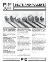
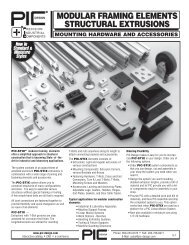
CLUTCHES, BRAKES<br />
& COUPLINGS<br />
1. Clutch<br />
2. Power on Brake<br />
3. Power off Brake<br />
4. Slip Clutch Assembly<br />
5. Slip Coupling<br />
6. Zero Adjustable Coupling<br />
7. Bellows Coupling<br />
8. Miniature Oldham Coupling<br />
9. Multi-Jaw Coupling<br />
10. Flexible Coupling<br />
11. Water Spring Coupling<br />
12. Universal Lateral Coupling<br />
13. Molded Universal Joint<br />
14. Precision Universal Joint<br />
15. Roller Clutch<br />
1.<br />
4.<br />
8.<br />
9.<br />
10.<br />
5.<br />
11.<br />
2.<br />
7.<br />
13.<br />
12.<br />
3.<br />
6.<br />
14.<br />
15.<br />
Bellows Couplings<br />
Zero Adjustable Couplings<br />
Flexible Couplings<br />
Miniature Oldham Couplings<br />
Wafer Oldham Couplings<br />
Universal Lateral Couplings<br />
Multi-Jaw Couplings<br />
Precision Universal Joint Couplings<br />
Molded Universal Joint Couplings<br />
Precision Sleeve Couplings<br />
Flexible Zero Backlash Couplings<br />
Spider Coupling<br />
www.pic-design.<strong>com</strong><br />
Interactive catalog ■ CAD ■ e-<strong>com</strong>merce<br />
DESIGN<br />
®<br />
Phone: 800-243-6125 ■ FAX: 203-758-8271<br />
E-Mail: sales@pic-design.<strong>com</strong><br />
7-1
TECHNICAL SECTION<br />
Industrial Clutches and Brakes<br />
Couplings<br />
Coupling Type<br />
COUPLING SELECTION GUIDE<br />
Angular Misalignment > 5 o<br />
Angular Misalignment < 5 o<br />
Lateral Misalignment > .010"<br />
Withstand Shock Loads<br />
Vibration Dampening<br />
Bellows X X X X X X X X<br />
Zero Adjustable X X X X X X X X<br />
Flexible X X X X X X X<br />
Oldham X X X X X<br />
Wafer Spring X X X X X X X X X X X<br />
Universal Lateral X X X X X X X X X<br />
Multi-Jaw X X X X X X<br />
Universal Joint X X X X X X X<br />
Molded<br />
Universal Joint<br />
X X X X X X X X<br />
Sleeve Coupling X X X X X X X<br />
Flexible Zero<br />
Coupling<br />
X X X X X X X X X X<br />
Flexible K X X X X X X X X X X<br />
Spider Coupling X X X X X X X X<br />
Bellows Couplings<br />
The ideal solution where shafts are angularlly and<br />
laterally misaligned. They feature a stainless steel hub<br />
pinned to a stainless steel bellows.<br />
Zero Adjustable Couplings<br />
Get the same characteristics as on the bellows type<br />
coupling, except these couplings have an adjustable<br />
hub for zeroing synchros and other similar devices.<br />
High Speeds<br />
High Torque<br />
High Ambient Temperature<br />
Clean Room Environment<br />
Stepper Motors<br />
Reversing Drives<br />
Maintenance Required<br />
Vacuum Environment (No Lube)<br />
Compressibility<br />
Electrically Insulated<br />
Flexible Couplings<br />
These will isolate vibration, absorb shock<br />
loads and electrically insulate. They feature a<br />
molded neoprene body connected to<br />
stainless steel hubs.<br />
Miniature Oldham Couplings<br />
A choice of center block of oil impregnated<br />
bronze or nylon (eliminates metal-to-metal<br />
contact from taking place) between the hubs.<br />
Use these couplings in high-torque<br />
applications.<br />
Wafer Spring Couplings<br />
The choice for your highest torque applications<br />
and where there is up to 8 o of angular<br />
and .03 inches of lateral misalignment.<br />
Universal Lateral Couplings<br />
Not only will these couplings provide<br />
electrical insulation, but they can handle up<br />
to 10 o angular and .05 inches of lateral<br />
misalignment.<br />
Multi-Jaw Couplings<br />
Interlocking teeth permit precision coupling/<br />
decoupling with limited transmission error<br />
between two stainless steel hubs.<br />
Universal Joint Couplings<br />
Working angles up to 30 o<br />
are no problem<br />
when you use these coupling. Standard in<br />
either Stainless Steel or Delrin.<br />
Precision Sleeve Couplings<br />
Use them when coupling shafts of similar or<br />
dissimilar diameters. This allows you to<br />
couple inch to inch, millimeter to millimeter,<br />
and inch to millimeter shafts.<br />
Flexible Zero Backlash Couplings<br />
Work well in high accuracy systems. Stainless<br />
steel or aluminum one-piece construction with<br />
high torsional stiffness, constant velocity, and<br />
very low wind up.<br />
Flexible K Couplings<br />
An excellent choice for use in abrasive dust<br />
environments and where maximum flexibility<br />
is required. The hubs are zinc plated; the<br />
bodies are polyurethane.<br />
Spider Couplings<br />
These provide high torque transmission<br />
without backlash or vibration due to the use of<br />
a chemically resistant and electrical isolating<br />
elastomer insert.<br />
Shaft Extensions<br />
Used to add an additional inch of shaft length<br />
or facilitate a change from special to standard<br />
shaft diameter. — See Section 6.<br />
7-2<br />
Phone: 800-243-6125 ■ FAX: 203-758-8271<br />
E-Mail: sales@pic-design.<strong>com</strong><br />
DESIGN<br />
®<br />
www.pic-design.<strong>com</strong><br />
Interactive catalog ■ CAD ■ e-<strong>com</strong>merce<br />
X
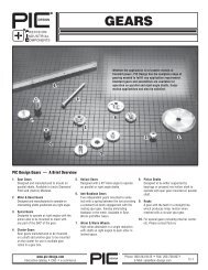
FLANGE MOUNTED-POWER OFF BRAKES<br />
24 VDC and 120 VAC 3 /16", 1 /4", 5 /16", and 3 /8" Bores<br />
Diagram 1<br />
Diagram 2<br />
Electrical<br />
Mechanical<br />
H<br />
H<br />
Air Gap Set<br />
At Factory<br />
PIC<br />
B C D E F G H I J K L Diagram<br />
Series A Max. Nom. Max. Max. Min. Ref. Max. ±.500 Nom. Min. Nom.<br />
RY5 .890 .710 .072 .510 1.485 .320 .280 1.375 12.0 1.180 .113 3/8 1<br />
RY6 1.060 .870 .115 .755 1.910 .380 .410 1.752 12.0 1.545 .113 9/16<br />
RY7 1.400 1.200 1.255 .955 2.465 .450 .781 2.436 12.0 2.125 .170 5/8 2<br />
RY8 1.400 1.200 1.255 .722 2.465 .605 .781 2.436 12.0 2.125 .170 5/8<br />
FLANGE MOUNTED-POWER ON BRAKES<br />
24 VDC and 90 Volts DC 3 /16", 1 /4", 5 /16", and 3 /8" Bores<br />
To Order Alternate Bores and Voltages, Consult Factory<br />
PIC<br />
B C E F G H I J K L<br />
Series A Nom. Max. Nom. Max. ±.001 Max. ±.001 Nom. Min. ±.500<br />
RX1 .885 .634 .905 .572 .034 NA .980 1.1995 1.030 .094 12.0<br />
RX2 .974 .650 1.160 .583 .052 NA 1.230 1.498 1.312 .123 12.0<br />
RX3 1.309 .867 1.500 .805 .063 NA 1.567 1.999 1.750 .156 12.0<br />
RX4 1.269 .848 1.780 .745 .064 NA 1.943 2.436 2.125 .186 12.0<br />
Series Typical Out-of-Box Rated Static Typical Torques After<br />
Torques lb.-in. Torques lb.-in. Burnishing lb.-in.<br />
RX1 2 2.5 3<br />
RX2 5 6 8<br />
RX3 8 10 15<br />
RX4 12 15 20<br />
www.pic-design.<strong>com</strong><br />
Interactive catalog ■ CAD ■ e-<strong>com</strong>merce<br />
DESIGN<br />
®<br />
Phone: 800-243-6125 ■ FAX: 203-758-8271<br />
E-Mail: sales@pic-design.<strong>com</strong><br />
7-3
SHAFT MOUNTED-CLUTCHES<br />
24 and 90 Volts DC 3 /16", 1 /4", 5 /16", and 3 /8" Bores<br />
SLIP CLUTCHES — CONTINUOUS SLIP OPERATION<br />
1 /8", 3 /16", and 1 /4" Bores and 3, 4, 6 mm Bores<br />
T17-4, MCH2-4<br />
All Other Models<br />
7-4<br />
Phone: 800-243-6125 ■ FAX: 203-758-8271<br />
E-Mail: sales@pic-design.<strong>com</strong><br />
DESIGN<br />
®<br />
www.pic-design.<strong>com</strong><br />
Interactive catalog ■ CAD ■ e-<strong>com</strong>merce
SLIP CLUTCHES — CONTINUOUS SLIP OPERATION<br />
Adjustable Torque<br />
Material:<br />
Housing — Steel; Zinc Plated<br />
Clutch Plates — Brass<br />
Friction Plates — Proprietary (Non Asbestos)<br />
Maximum RPM =<br />
WATTS (From Table Below)<br />
Torque (oz.- in.) x .0007<br />
A<br />
Dimensions And Capacity Rating<br />
Bore Capacity Friction<br />
B +.002 C D ±.005 E EE F<br />
oz.- in. Watts Surfaces -.000<br />
Part No*<br />
1.00 .250 1.06 .76 .25 .3 to 32 1.0 2 T25-164-2S<br />
Cartridge<br />
T25-164-2H<br />
1.00 .250 1.31 .76 .25 Enclosed 4.8 to 160 5.8 8 T25-164-8S<br />
T25-164-8H<br />
1.25 .250 1.50 .76 .25 .50 1.00 1.6 to 160 6.0 8 T25-204-S<br />
T25-204-H<br />
1.50 .375 2.50 1.01 .37 .75 1.75 8 to 400 14.5 12 T25-246-S<br />
T25-246-H<br />
2.00 .500 2.87 1.38 .50 1.00 1.88 12.8 to 800 29.0 12 T25-328-S<br />
T25-328-H<br />
Open Plate<br />
Features:<br />
● A multi plate slip clutch<br />
● Adjustable torque<br />
● Preset torque available on<br />
special orders (Torque setting<br />
± 10%)<br />
● Can be used as a slip coupling<br />
● Backlash of 6 o is standard<br />
● Constant tension<br />
● Overload protection<br />
● Controlled slip<br />
● Clutches exhibit same<br />
torque in either direction<br />
● Shaft to shaft clutch/<br />
coupling or thru shaft to<br />
pulley, gear, etc.<br />
● Bronze bearing in housing<br />
for thru-shaft to pulley<br />
models<br />
● Low stick-slip ratio<br />
Capacity at continuous duty, 50 RPM, 25 million cycles (Rev)<br />
*Note: ● For shaft to shaft coupling, set screws in both housing<br />
and cartridge — use Part No. ending with “S”<br />
● For thru shaft to housing (pulley, gear, etc.), bronze bearing in<br />
housing, set screw in cartridge — use Part No. ending with “H”<br />
● Metric bores can be ac<strong>com</strong>plished by use of bore reducers<br />
(5,6,8 & 10 mm finished bores) found in the catalog<br />
● Consult factory for other bore sizes<br />
SLIP COUPLINGS — CONTINUOUS SLIP OPERATION<br />
1 /8", 3 /16", and 1 /4" Bores and 3, 4, 6 mm Bores<br />
Max<br />
.63<br />
.63<br />
1.01<br />
12.5<br />
16<br />
16<br />
www.pic-design.<strong>com</strong><br />
Interactive catalog ■ CAD ■ e-<strong>com</strong>merce<br />
DESIGN<br />
®<br />
Phone: 800-243-6125 ■ FAX: 203-758-8271<br />
E-Mail: sales@pic-design.<strong>com</strong><br />
7-5
SLIP CLUTCH ASSEMBLY — ADJUSTABLE-MOMENTARY OVERLOAD*<br />
Pin Hub ■ 1 /8", 3 /16", and 1 /4" Bores and 3, 4, 6 mm Bores<br />
Clamp Type ■ 1 /8", 3 /16", and 1 /4" Bores and 3, 4, 6 mm Bores<br />
IN-LINE COUPLING & SLIP CLUTCHES — ADJUSTABLE-INTERMITTENT DUTY<br />
1 /8", 3 /16", and 1 /4" Bores and 3, 4, 6 mm Bores<br />
7-6<br />
Phone: 800-243-6125 ■ FAX: 203-758-8271<br />
E-Mail: sales@pic-design.<strong>com</strong><br />
DESIGN<br />
®<br />
www.pic-design.<strong>com</strong><br />
Interactive catalog ■ CAD ■ e-<strong>com</strong>merce
ROLLER CLUTCHES<br />
■ Ideal for indexing, backstopping<br />
or overrunning operations<br />
■ Free rolling one way, drives in<br />
opposite direction<br />
■ Light weight, low profile<br />
■ High indexing, frequency<br />
■ Temperature max 200°F<br />
■ Maximum Backlash<br />
■ Shaft should be RC58 min. with<br />
16μ" finish or better<br />
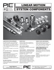
BACKLASH FREE ELASTOMER JAW “SPIDER” COUPLING<br />
1 /8" to 1 /2" Diameter Bores and 4mm to 12mm Bores<br />
Features:<br />
■ For electrical isolation and chemical resistance<br />
■ Coupling with Integral radial clamp using<br />
socket head cap screws<br />
■ High torsional stiffness:<br />
- Static 4.5 Lbf-Ft/deg (700Nm/rad)<br />
- Dynamic 9 Lbf-Ft/deg (350Nm/rad)<br />
■ Misalignment Tolerances:<br />
- Angular 0.8°<br />
- Lateral .002" (.06 mm)<br />
- Axial ± .039" (1 mm)<br />
■ Temp. Range (due to elastomer)<br />
22° to 248°F (-30° to 120°C)<br />
Specifications: Inch / (Metric)<br />
■ Rated Torque 106 Lbf-in / (12Nm)<br />
■ Over all length 1.02" / (26mm)<br />
■ C Fit Length .315" / (8mm)<br />
■ Clamping Screw M3<br />
■ Torque to tighten screw 17.7 Lbf-in / (2Nm)<br />
■ Aprox. Weight .07 oz / (.02 kg)<br />
■ Bore Tolerance +.001" / (H7)<br />
-.000<br />
Material:<br />
■ Hubs: High Strength Aluminum<br />
■ Elastomer Insert: Precision molded, wear<br />
resistant and thermally stable polymer 64<br />
Shore D<br />
www.pic-design.<strong>com</strong><br />
Interactive catalog ■ CAD ■ e-<strong>com</strong>merce<br />
Inch bores<br />
B 1 / B 2<br />
Bore<br />
Part<br />
Number<br />
.188 T13E-18<br />
.250 T13E-25<br />
.250/.188 T13E-2518<br />
.3125 T13E-31<br />
.3125/.188 T13E-3118<br />
.3125/.250 T13E-3125<br />
.375 T13E-37<br />
.375/.188 T13E-3718<br />
Inch bores<br />
B 1 / B 2<br />
Bore<br />
DESIGN<br />
®<br />
.157<br />
Part<br />
Number<br />
.375/.250 T13E-3725<br />
.375/.3125 T13E-3731<br />
.500 T13E-50<br />
.500/.188 T13E-5018<br />
.500/.250 T13E-5025<br />
.500/3125 T13E-5031<br />
.500/.375 T13E-5037<br />
Other bore sizes and <strong>com</strong>binations available between inch<br />
(.188 to .500) and metric (4mm to 12mm) ranges.<br />
Please consult factory.<br />
"B1"<br />
1.023<br />
B 1 / B 2<br />
Bore<br />
.315<br />
Metric Bores<br />
"B2"<br />
Part<br />
Number<br />
.984<br />
M3<br />
Screw<br />
4 T13E-4M<br />
5 T13E-5M<br />
5/4 T13E-5M4M<br />
6 T13E-6M<br />
6/5 T13E-6M5M<br />
6/4 T13E-6M4M<br />
8 T13E-8M<br />
8/4 T13E-8M4M<br />
8/5 T13E-8M5M<br />
8/6 T13E-8M6M<br />
12/10 T13E-12M10M<br />
Metric to Inch<br />
B 1 / B 2<br />
Bore<br />
4M/.188<br />
5M/.188<br />
4M/.250<br />
5M/.375<br />
6M/.375<br />
4M/.500<br />
6M /.500<br />
10M/.500<br />
12M/.500<br />
Phone: 800-243-6125 ■ FAX: 203-758-8271<br />
E-Mail: sales@pic-design.<strong>com</strong><br />
.315<br />
Part<br />
Number<br />
T13E-4M18<br />
T13E-5M18<br />
T13E-4M25<br />
T13E-5M37<br />
T13E-6M37<br />
T13E-4M50<br />
T13E-6M50<br />
T13E-10M50<br />
T13E-12M50<br />
7-7
WAFER SPRING COUPLINGS<br />
.12 To .50 Inch Bores and 3 To 12 mm Bores<br />
Material: Hubs and center members – Anodized Aluminum<br />
Leaves – 17-7PH S.S.<br />
Fasteners – Stainless Steel<br />
7-8<br />
Phone: 800-243-6125 ■ FAX: 203-758-8271<br />
E-Mail: sales@pic-design.<strong>com</strong><br />
DESIGN<br />
®<br />
www.pic-design.<strong>com</strong><br />
Interactive catalog ■ CAD ■ e-<strong>com</strong>merce
BELLOWS COUPLINGS<br />
.12 to 3 /8" Bore and 3 mm to 10 mm Bores<br />
PIN HUB<br />
SPLIT HUB<br />
Material: Stainless Steel<br />
Torque .................................... 75 oz. in.<br />
Shaft to Shaft Misalignment ....... 0.010"<br />
Angular Misalignment ....................... 5 O<br />
Backlash ................................ Negligible<br />
Shaft<br />
Set Clamp Pin Hub Split Hub<br />
Size<br />
A B C<br />
Screw No. (Ref.) Part No. Part No.<br />
.12 to 1/8<br />
.1200 .312 .188 #2-56<br />
.1248<br />
L1-4 T1-15 T1-18<br />
.12 to 1/4<br />
.1200 .312 .188 #2-56 L1-4<br />
.2498 .500 .312 #6-32 L1-6<br />
T1-17 T1-20<br />
Inch 1/8 to 1/8 .1248 .312 .188 #2-56 L1-4 T1-1 T1-8<br />
Bores<br />
.1248 .312 .188 #2-56 L1-4<br />
Toler. 1/8 to 3/16<br />
.1873 .375 .250 #4-40 L1-5<br />
T1-4 T1-11<br />
+.0005<br />
.1248 .312 .188 #2-56 L1-4<br />
-.0000 1/8 to 1/4<br />
.2498 .500 .312 #6-32 L1-6<br />
T1-5 T1-12<br />
3/16 to 3/16 .1873 .375 .250 #4-40 L1-5 T1-2 T1-9<br />
3/16 to 1/4<br />
.1873 .375 .250 #4-40 L1-5<br />
.2498 .500 .312 #6-32 L1-6<br />
T1-6 T1-13<br />
1/4 to 1/4 .2498 .500 .312 #6-32 L1-6 T1-3 T1-10<br />
5/16 to 5/16 .3123 .500 .375 #6-32 L1-20 T1-21 T1-23<br />
3/8 to 3/8 .3748 .625 .438 #8-32 L1-21 T1-22 T1-24<br />
Metric<br />
Bores<br />
Toler.<br />
+.013<br />
-.000<br />
Dimensions below are in millimeters.<br />
3 to 3 2.995 7.92 4.78 M2X.4 L1-4 MCU1-1 MCU2-1<br />
3 to 4<br />
2.995 7.92 4.78 L1-4<br />
M2X.4<br />
3.995 9.52 6.35 L1-5<br />
MCU1-2 MCU2-2<br />
3 to 6<br />
2.995 7.92 4.78 L1-4<br />
M2X.4<br />
5.995 12.70 7.92 L1-6<br />
MCU1-3 MCU2-3<br />
4 to 4 3.995 9.52 6.35 M2X.4 L1-5 MCU1-4 MCU2-4<br />
4 to 6<br />
3.995 9.52 6.35 L1-5<br />
M2X.4<br />
5.995 12.70 7.92 L1-6<br />
MCU1-5 MCU2-5<br />
6 to 6 5.995 12.70 7.92 M3X.5 L1-6 MCU1-6 MCU2-6<br />
8 to 8 7.995 12.70 9.60 M3X.5 L1-20 MCU1-7 MCU2-7<br />
10 to 10 9.995 16.40 11.60 M4X.7 L1-21 MCU1-8 MCU2-8<br />
ZERO ADJUSTABLE COUPLINGS<br />
1 /8" to 3 /8" Bore and 3 mm to 10 mm Bores<br />
PIN HUB<br />
SPLIT HUB<br />
Material: Stainless Steel<br />
Shaft<br />
Set Clamp Pin Hub Split Hub<br />
Size<br />
A B C<br />
Screw No. (Ref.) Part No. Part No.<br />
1/8 to 1/8 .1248 5/16 .188 #2-56 L1-4 T9-1 T10-1<br />
1/8 to 3/16<br />
.1248 5/16 .188 #2-56 L1-4<br />
.1873 3/8 .250 #4-40 L1-5<br />
T9-7 T10-7<br />
Inch<br />
.1248 5/16 .188 #2-56 L1-4<br />
Bores 1/8 to 1/4<br />
Toler.<br />
.2498 1/2 .312 #6-32 L1-6<br />
T9-8 T10-8<br />
+.0005 3/16 to 3/16 .1873 3/8 .250 #4-40 L1-5 T9-2 T10-2<br />
-.0000<br />
.1873 3/8 .250 #4-40 L1-5<br />
3/16 to 1/4<br />
.2498 1/2 .312 #6-32 L1-6<br />
T9-9 T10-9<br />
1/4 to 1/4 .2498 1/2 .312 #6-32 L1-6 T9-3 T10-3<br />
5/16 to 5/16 .3123 .500 .375 #6-32 L1-20 T9-11 T10-11<br />
3/8 to 3/8 .3748 .625 .438 #8-32 L1-21 T9-12 T10-12<br />
Metric<br />
Bores<br />
Toler.<br />
+.013<br />
-.000<br />
Dimensions below are in millimeters.<br />
3 to 3 2.995 7.92 4.78 M2X.4 L1-4 MCU3-1 MCU4-1<br />
3 to 4<br />
2.995 7.92 4.78 L1-4<br />
M2X.4<br />
3.995 9.52 6.35 L1-5<br />
MCU3-2 MCU4-2<br />
3 to 6<br />
2.995 7.92 4.78 L1-4<br />
M2X.4<br />
5.995 12.70 7.92 L1-6<br />
MCU3-3 MCU4-3<br />
4 to 4 3.995 9.52 6.35 M2X.4 L1-5 MCU3-4 MCU4-4<br />
4 to 6<br />
3.995 9.52 6.35 L1-5<br />
M2X.4<br />
5.995 12.70 7.92 L1-6<br />
MCU3-5 MCU4-5<br />
6 to 6 5.995 12.70 7.92 M3X.5 L1-6 MCU3-6 MCU4-6<br />
8 to 8 7.995 12.70 9.60 M3X.5 L1-20 MCU3-7 MCU4-7<br />
10 to 10 9.995 16.40 11.60 M4X.7 L1-21 MCU3-8 MCU4-8<br />
* Adjustable end is first shaft size shown.<br />
One turn of adjusting screw rotates coupling hub 12 degrees. Hub and shaft remain fixed during adjustment.<br />
www.pic-design.<strong>com</strong><br />
Interactive catalog ■ CAD ■ e-<strong>com</strong>merce<br />
DESIGN<br />
®<br />
Phone: 800-243-6125 ■ FAX: 203-758-8271<br />
E-Mail: sales@pic-design.<strong>com</strong><br />
7-9
FLEXIBLE COUPLINGS<br />
.12 to 1 /4" Bore and 3 mm to 6 mm Bores<br />
PIN HUB<br />
SPLIT HUB<br />
Inch<br />
Bores<br />
Toler.<br />
+.0005<br />
-.0000<br />
Metric<br />
Bores<br />
Toler.<br />
+.013<br />
-.000<br />
Shaft A B C Set Clamp Pin Hub Split Hub<br />
Size Screw No. (Ref.) Part No. Part No.<br />
.12 to 1/8<br />
.1200<br />
.1248<br />
5/16 .188 #2-56 L1-4 T11-7 T12-7<br />
.12 to 3/16<br />
.1200<br />
.1873<br />
5/16<br />
3/8<br />
.188<br />
.250<br />
#2-56<br />
#4-40<br />
L1-4<br />
L1-5<br />
T11-10 T12-10<br />
.12 to 1/4<br />
.1200 5/16 .188 #2-56 L1-4<br />
.2498 1/2 .312 #6-32 L1-6<br />
T11-9 T12-9<br />
1/8 to 1/8 .1248 5/16 .188 #2-56 L1-4 T11-1 T12-1<br />
1/8 to 3/16<br />
.1248<br />
.1873<br />
5/16<br />
3/8<br />
.188<br />
.250<br />
#2-56<br />
#4-40<br />
L1-4<br />
L1-5<br />
T11-4 T12-4<br />
1/8 to 1/4<br />
.1248<br />
.2498<br />
5/16<br />
1/2<br />
.188<br />
.312<br />
#2-56<br />
#6-32<br />
L1-4<br />
L1-6<br />
T11-5 T12-5<br />
5/32 to 3/16<br />
.1562 5/16<br />
.250<br />
#2-56<br />
.1873 3/8 #4-40<br />
L1-5 T11-8 T12-8<br />
3/16 to 3/16 .1873 3/8 .250 #4-40 L1-5 T11-2 T12-2<br />
3/16 to 1/4<br />
.1873<br />
.2498<br />
3/8<br />
1/2<br />
.250<br />
.312<br />
#4-40<br />
#6-32<br />
L1-5<br />
L1-6<br />
T11-6 T12-6<br />
1/4 to 1/4 .2498 1/2 .312 #6-32 L1-6 T11-3 T12-3<br />
Dimensions below are in millimeters.<br />
UNIVERSAL LATERAL COUPLINGS<br />
1 /8", 3 /8", and 1 /4" Bores and 3, 4, 6 mm Bores<br />
3 to 3 2.995 7.92 4.78 M2X.4 L1-4 MCU7-1 MCU8-1<br />
3 to 4<br />
2.995 7.92 4.78 L1-4<br />
M2X.4<br />
3.995 9.52 6.35 L1-5<br />
MCU7-2 MCU8-2<br />
3 to 6<br />
2.995 7.92 4.78 L1-4<br />
M2X.4<br />
5.995 12.70 7.92 L1-6<br />
MCU7-3 MCU8-3<br />
4 to 4 3.995 9.52 6.35 M2X.4 L1-5 MCU7-4 MCU8-4<br />
4 to 6<br />
3.995 9.52 6.35 L1-5<br />
M2X.4<br />
5.995 12.70 7.92 L1-6<br />
MCU7-5 MCU8-5<br />
6 to 6 5.995 12.70 7.92 M3X.5 L1-6 MCU7-6 MCU8-6<br />
Features<br />
- Simultaneous lateral and<br />
angular misalignment<br />
- Corrosion resistant<br />
- Electrically insulated<br />
- Light weight and space<br />
saving<br />
- No lubrication required<br />
- Separable<br />
Specifications<br />
Maximum angular misalignment:<br />
Maximum lateral misalignment:<br />
Maximum working torque:<br />
Backlash:<br />
Weight (1/2" bore):<br />
Trunnion material:<br />
Annular ring material:<br />
Standard connection to shaft:<br />
INCH<br />
Tolerance B Part No.<br />
.1200 T16-7<br />
.1200 & .1250 T16-8<br />
.1250 T16-1<br />
.1250 & .1875 T16-2<br />
+.001" .1250 & .250 T16-3<br />
-.000" .1875 T16-4<br />
.1875 & .250 T16-5<br />
.1875 & .3125 T16-9<br />
.2500 T16-6<br />
.2500 & .3125 T16-10<br />
10 o<br />
.3125 T16-11<br />
.050 inches<br />
15 lb. in.<br />
Negligible<br />
.5 ounces<br />
Nickel plated metal<br />
Delrin<br />
Socket head cup<br />
point set screw<br />
METRIC<br />
Tolerance B Part No.<br />
3 MUJ1-1<br />
4 MUJ1-4<br />
3 &4 MUJ1-2<br />
3 & 5 MUJ1-7<br />
+.025 mm 3 & 6 MUJ1-3<br />
-.000 mm 4 & 5 MUJ1-8<br />
4 & 6 MUJ1-5<br />
5 & 5 MUJ1-9<br />
5 & 6 MUJ1-10<br />
6 MUJ1-6<br />
INCH TO METRIC<br />
Tolerance B Part No.<br />
Inch Bores .1875" & 5 mm T16C4-9<br />
+.001" .1875" & 6 mm T16C4-6<br />
-.000" .2500" & 3 mm T16C6-1<br />
Metric Bores .2500" & 4 mm T16C6-4<br />
+.025 mm .2500" & 5 mm T16C6-9<br />
-.000 mm .2500" & 6 mm T16C6-6<br />
7-10<br />
Phone: 800-243-6125 ■ FAX: 203-758-8271<br />
E-Mail: sales@pic-design.<strong>com</strong><br />
DESIGN<br />
®<br />
www.pic-design.<strong>com</strong><br />
Interactive catalog ■ CAD ■ e-<strong>com</strong>merce
MULTI-JAW COUPLINGS — 64 PITCH<br />
1 /8", 3 /16", and 1 /4" Bores and 3, 4, 6 mm Bores<br />
48 TEETH - 3/4" DIA.<br />
32 TEETH - 17/32" DIA.<br />
MINIATURE OLDHAM COUPLINGS<br />
1 /8", 3 /16", and 1 /4" Bores and 3, 4, 6 mm Bores<br />
www.pic-design.<strong>com</strong><br />
Interactive catalog ■ CAD ■ e-<strong>com</strong>merce<br />
DESIGN<br />
®<br />
Phone: 800-243-6125 ■ FAX: 203-758-8271<br />
E-Mail: sales@pic-design.<strong>com</strong><br />
7-11
PRECISION SLEEVE COUPLINGS<br />
1 /8" to 1 /2" Bores and 3 to 12 mm Bores<br />
PRECISION SLEEVE COUPLINGS<br />
1 /8" to 3 /8" Bores and 3 to 12 mm Bores<br />
7-12<br />
Phone: 800-243-6125 ■ FAX: 203-758-8271<br />
E-Mail: sales@pic-design.<strong>com</strong><br />
DESIGN<br />
®<br />
www.pic-design.<strong>com</strong><br />
Interactive catalog ■ CAD ■ e-<strong>com</strong>merce
FLEXIBLE-ZERO BACKLASH COUPLING<br />
1 /8" to 5 /8" Diameter Bores and 4 mm to 12 mm Bores<br />
Misalignment Tolerances<br />
B<br />
Momentary<br />
Bore L D Integral Dynamic Torsional Parallel Axial Part<br />
+.002 Length ±.016 Dia. ±.016 Clamp Torque Rate Angular Offset Motion Number<br />
-.000 Screw Size Inch Lbs. (Degree/Lb In) (Degree) (Inches) (Inches)<br />
.125 0.750 0.500 1-72 7 0.48 5 .010 ±.010 T22S-12<br />
.188 1.250 0.750 4-40 14 0.30 3 .010 ±.008 T22A-18<br />
.188 0.900 0.750 4-40 20 0.16 5 .010 ±.010 T22S-18<br />
.188/.250 1.060 0.875 6-32 34 0.086 5 0.03 ±0.01 T22S-1825S<br />
.250 1.500 1.000 6-32 31 0.13 3 .010 ±.008 T22A-25<br />
.250 1.250 1.000 6-32 52 0.062 5 .010 ±.010 T22S-25<br />
.250 1.750 1.000 6-32 51 0.098 5 .03 ±.010 T22S-25S<br />
.250/.125 0.900 0.750 4-40 8.6 0.68 5 .010 ±.010 T22A-2512<br />
.250/.188 1.060 0.875 6-32 17 0.28 5 .010 ±.010 T22A-2518<br />
.250/.188 1.250 0.750 4-40 12 0.40 3 .010 ±.008 T22A-2518D<br />
.250/.375 1.500 1.000 6-32 25 0.19 3 .010 ±.008 T22A-2537<br />
.313 1.500 1.000 6-32 29 0.16 3 .010 ±.008 T22A-31<br />
.313 1.250 1.000 6-32 47 0.086 5 .010 ±.010 T22S-31<br />
.313/.250 1.750 1.000 6-32 46 0.14 5 0.03 ±0.01 T22S-2531<br />
.313/.375 2.375 1.250 10-32 91 0.062 5 0.03 ±0.01 T22S-3137<br />
.375 1.750 1.250 10-24 58 0.08 3 .010 ±.008 T22A-37<br />
.375 2.375 1.250 10-32 91 0.062 5 .030 ±.010 T22S-37<br />
.500 2.250 1.500 10-24 115 0.042 3 .010 ±.008 T22A-50<br />
.500 2.625 1.500 10-32 170 0.037 5 .030 ±.010 T22S-50<br />
.625 2.500 2.000 1/4-20 215 0.020 3 .010 ±.008 T22A-62<br />
.625 3.000 2.000 1/4-28 319 0.018 5 .030 ±.010 T22S-62<br />
Dimensions Below are in Millimeters<br />
Misalignment Tolerances<br />
B<br />
Bore L D Screw Parallel Axial Part<br />
+.025 ± .40 ± .40 Size Nm Degree/Nm Angular Offset Motion Number<br />
-.000 (Degree) (Inches) (Inches)<br />
3.17 19.05 12.70 1-72 .80 0.054 5 .254 ±.254 T22S-12<br />
5.00 38.10 25.40 6-32 3.50 0.015 3 .254 ±.203 MT22A-05<br />
5.00 31.75 25.40 6-32 5.88 0.007 5 .254 ±.254 MT22S-05<br />
6.00 44.45 31.75 10-24 6.55 0.009 3 .254 ±.203 MT22A-06<br />
8.00 60.32 31.75 10-32 10.28 0.007 5 .762 ±.254 MT22S-08<br />
10.00 57.15 38.10 10-24 13.00 0.005 3 .254 ±.203 MT22A-10<br />
10.00 66.67 38.10 10-32 19.21 0.004 5 .762 ±.254 MT22S-10<br />
12.00 63.50 50.80 1/4-20 24.30 0.002 3 .254 ±.203 MT22A-12<br />
12.00 76.20 50.80 1/4-28 36.05 0.002 5 .762 ±.254 MT22S-12<br />
www.pic-design.<strong>com</strong><br />
Interactive catalog ■ CAD ■ e-<strong>com</strong>merce<br />
DESIGN<br />
®<br />
Phone: 800-243-6125 ■ FAX: 203-758-8271<br />
E-Mail: sales@pic-design.<strong>com</strong><br />
7-13
(K) FLEXIBLE COUPLINGS<br />
BORE REDUCERS<br />
Inch And Metric<br />
Material: Aluminum<br />
Inch to inch and inch to metric bore reducers adapt a coupling, clutch, pulley<br />
and other bores to a number of shaft diameters when fitted to a pin hub (set<br />
screw) or split hubs.<br />
Grip relies on adequate contact area between the shaft and reducer.<br />
OD<br />
+.0005<br />
-.001<br />
Inch to Inch Reduction<br />
ID<br />
+.001<br />
-.000<br />
L<br />
±.010<br />
Part No.<br />
.250 .125 3/8 R-04-02-375<br />
.250 .187 3/8 R-04-03-375<br />
.375 .250 1/2 R-06-04-500<br />
.375 .3125 1/2 R-06-05-500<br />
.500 .375 1/2 R-08-06-750<br />
Release of residual stresses after slitting may result in slight springing of the<br />
material, — this can be corrected by finger pressure.<br />
For optimum fastening install bore reducers as shown:<br />
“S” = Two Set Screw Position<br />
“C” = One Set Screw<br />
“T” = Tangential Screw In Clamp Hub<br />
Inch to Metric Reduction<br />
OD<br />
+.0005<br />
-.001<br />
ID<br />
+.025<br />
-.000 (mm)<br />
L<br />
±.25<br />
(mm)<br />
Part No.<br />
.250 5 8 (.312) MR-04-05-08<br />
.375 6 11 (.433) MR-06-06-11<br />
.375 8 12 (.472) MR-06-08-12<br />
.500 10 16 (.625) MR-08-10-16<br />
.625 12 16 (.625) MR-10-12-12<br />
Bore Reducers With Thicker Walls May Have Slot In Opposite Wall For Proper Flexibility.<br />
7-14<br />
Phone: 800-243-6125 ■ FAX: 203-758-8271<br />
E-Mail: sales@pic-design.<strong>com</strong><br />
DESIGN<br />
®<br />
www.pic-design.<strong>com</strong><br />
Interactive catalog ■ CAD ■ e-<strong>com</strong>merce
PRECISION UNIVERSAL JOINTS<br />
1 /8", 3 /16", and 1 /4" Bores and 3, 4, 6 mm Bores<br />
MOLDED UNIVERSAL JOINTS<br />
1 /8", 3 /16", and 1 /4" Bores and 3, 4, 6 mm Bores<br />
www.pic-design.<strong>com</strong><br />
Interactive catalog ■ CAD ■ e-<strong>com</strong>merce<br />
DESIGN<br />
®<br />
Phone: 800-243-6125 ■ FAX: 203-758-8271<br />
E-Mail: sales@pic-design.<strong>com</strong><br />
7-15