
Create successful ePaper yourself
Turn your PDF publications into a flip-book with our unique Google optimized e-Paper software.
R<br />
DESIGN<br />
RECISION<br />
NDUSTRIAL<br />
OMPONENTS<br />
R<br />
LINEAR MOTION<br />
SYSTEM COMPONENTS<br />
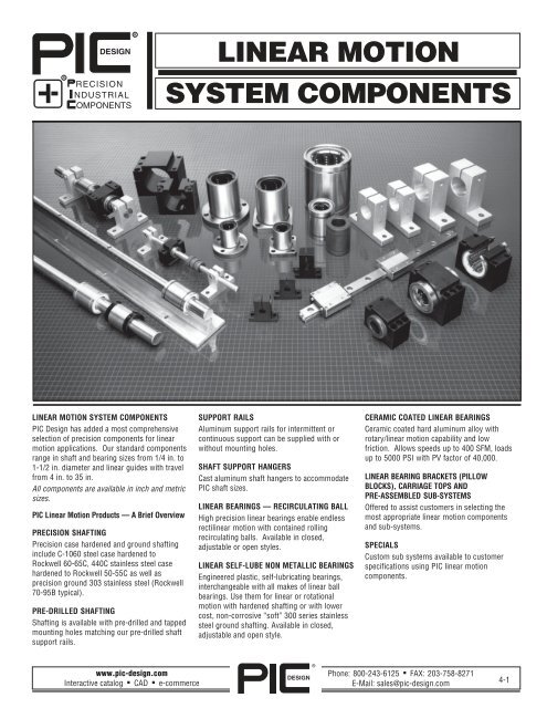
LINEAR MOTION SYSTEM COMPONENTS<br />
<strong>PIC</strong> <strong>Design</strong> has added a most comprehensive<br />
selection of precision components for linear<br />
motion applications. Our standard components<br />
range in shaft and bearing sizes from 1/4 in. to<br />
1-1/2 in. diameter and linear guides with travel<br />
from 4 in. to 35 in.<br />
All components are available in inch and metric<br />
sizes.<br />
<strong>PIC</strong> Linear Motion Products — A Brief Overview<br />
PRECISION SHAFTING<br />
Precision case hardened and ground shafting<br />
include C-1060 steel case hardened to<br />
Rockwell 60-65C, 440C stainless steel case<br />
hardened to Rockwell 50-55C as well as<br />
precision ground 303 stainless steel (Rockwell<br />
70-95B typical).<br />
PRE-DRILLED SHAFTING<br />
Shafting is available with pre-drilled and tapped<br />
mounting holes matching our pre-drilled shaft<br />
support rails.<br />
SUPPORT RAILS<br />
Aluminum support rails for intermittent or<br />
continuous support can be supplied with or<br />
without mounting holes.<br />
SHAFT SUPPORT HANGERS<br />
Cast aluminum shaft hangers to accommodate<br />
<strong>PIC</strong> shaft sizes.<br />
LINEAR BEARINGS — RECIRCULATING BALL<br />
High precision linear bearings enable endless<br />
rectilinear motion with contained rolling<br />
recirculating balls. Available in closed,<br />
adjustable or open styles.<br />
LINEAR SELF-LUBE NON METALLIC BEARINGS<br />
Engineered plastic, self-lubricating bearings,<br />
interchangeable with all makes of linear ball<br />
bearings. Use them for linear or rotational<br />
motion with hardened shafting or with lower<br />
cost, non-corrosive “soft” 300 series stainless<br />
steel ground shafting. Available in closed,<br />
adjustable and open style.<br />
CERAMIC COATED LINEAR BEARINGS<br />
Ceramic coated hard aluminum alloy with<br />
rotary/linear motion capability and low<br />
friction. Allows speeds up to 400 SFM, loads<br />
up to 5000 PSI with PV factor of 40,000.<br />
LINEAR BEARING BRACKETS (PILLOW<br />
BLOCKS), CARRIAGE TOPS AND<br />
PRE-ASSEMBLED SUB-SYSTEMS<br />
Offered to assist customers in selecting the<br />
most appropriate linear motion components<br />
and sub-systems.<br />
SPECIALS<br />
Custom sub systems available to customer<br />
specifications using <strong>PIC</strong> linear motion<br />
components.<br />
www.pic-design.com<br />
Interactive catalog ■ CAD ■ e-commerce<br />
DESIGN<br />
®<br />
Phone: 800-243-6125 ■ FAX: 203-758-8271<br />
E-Mail: sales@pic-design.com<br />
4-1
TECHNICAL SECTION<br />
Whatever your application, <strong>PIC</strong> <strong>Design</strong> offers a linear motion component<br />
that will work for you. Determine all loads, magnitude and<br />
direction, force and torque for your system requirements. Use of this<br />
data should enable users to select individual components, then select<br />
and specify all parts from this comprehensive offering.<br />
END SUPPORTS VS. RAIL SUPPORT<br />
Knowing the load to be carried by the linear motion system will help<br />
determine the proper diameter of the shafts.<br />
By using the shaft deflection table below, you can estimate the amount<br />
each shaft will deflect at the center of the stroke under maximum load.<br />
If deflection must be minimized, a continuous or intermittent support<br />
rail should be used.<br />
BEARING SPEEDS<br />
Linear bearing systems using recirculating ball bearings can travel at<br />
about 250 ft./min.; ceramic coated bearings at about 400 ft./min.; and<br />
our <strong>PIC</strong> self-lubricating linear bearing at 200 ft./min.<br />
SHAFT HARDNESS<br />
Rockwell 55 to 60C is required for “no grooving” of the shaft when<br />
using recirculating ball bearings or ceramic coated bearings. Use our<br />
<strong>PIC</strong> C1060 hardened and ground steel shaft; or where application<br />
dictates, 440 C stainless steel hardened and ground shaft. <strong>PIC</strong> self-lube<br />
linear bearings can be used with above shafting as well as the more<br />
economical and corrosion resistant “soft” 303 stainless steel (Rockwell<br />
70-95B).<br />
LINEAR MOTION GUIDES (See <strong>Section</strong> 2 — Linear Slides)<br />
These guides offer excellent positioning accuracy, low friction, high load<br />
bearing capabilities and greater compactness with recirculating ball or<br />
crossed roller slide design.<br />
LUBRICATION<br />
In applications where operating speeds are low and loads are light,<br />
linear recirculating ball bearings can be used without lubrication.<br />
However, to protect the highly polished bearing surfaces from corrosion<br />
and wear, a lubricant is recommended for most applications.<br />
Use light oil for good surface adhesion and greater bearing protection.<br />
Shaft Deflection Table For Use In <strong>Design</strong> And Application Of Linear Motion Devices<br />
Basic Dynamic Load Rating (C)<br />
This term means such load that, when a certain number of identical<br />
linear systems are individually run in the same conditions, 90% of them<br />
can run with the load (with a constant value in a constant direction) for<br />
a distance of 50 x 10 3 meters without damage caused by rolling fatigue.<br />
Static Safety Factor (fs)<br />
This factor is used to derate the basic static load (Co) for the sake of<br />
safety, depending on the conditions of use as shown in Table 1.<br />
Table 1. Static Safety Factors<br />
Condition of use<br />
Low limit of fs<br />
When in regular<br />
operating condition 1~2<br />
When especially smooth running<br />
performance is needed 2~4<br />
When the equipment is subject<br />
to vibration and shock 3~5<br />
Basic Static Load Rating (Co)<br />
This term defines a static load such that, at the contacting position<br />
where the maximum stress is exercised, the sum of the permanent<br />
deformation of the rolling body and that of the rolling plane is 0.0001<br />
time of the diameter of the rolling body.<br />
Rating Life (L)<br />
Rating life is the total travelling distance that 90% of a group of linear<br />
systems of the same size can reach without causing any flaking when<br />
they operate under the same conditions.<br />
The rating life can be obtained from the following equation with the<br />
basic dynamic load rating and the load on the linear system:<br />
C<br />
P<br />
C<br />
P<br />
For ball type: L = ( —— ) 3 ● 50<br />
For roller type: L = ( —— ) 10/ 3 ● 50<br />
L: Rating life (km) C: Basic Dynamic load rating (kgf)<br />
P: Load (kgf)<br />
4-2<br />
Phone: 800-243-6125 ■ FAX: 203-758-8271<br />
E-Mail: sales@pic-design.com<br />
DESIGN<br />
®<br />
www.pic-design.com<br />
Interactive catalog ■ CAD ■ e-commerce
PRECISION CASE HARDENED & GROUND SHAFTING<br />
Inch and Metric<br />
For Linear Motion Applications<br />
Materials and Hardness:<br />
C-1060 steel, case hardened to Rockwell 60-65C<br />
440 C stainless steel, case hardened to Rockwell 50-55C<br />
303 stainless steel, (for use with engineered plastic bearings),<br />
has approximate hardness of Rockwell 75-95B.<br />
C-1060 can be supplied with hard satin chrome finish at additional cost. Special orders only.<br />
(Adds .0001 to .0002 to diameter).<br />
Finish: Normally between 10 and 16 micro-inches RMS. Other finishes can be furnished to meet<br />
special requirements.<br />
Length Tolerances: Shafting is stocked in 6 to 10 foot lengths, and is supplied to required lengths<br />
±1/16" (±1.5mm). If required, closer length tolerances can be supplied at additional cost.<br />
Straightness: With the exception of 1/4" and 3/8" diameters, the standard straightness tolerance is<br />
.001"-.002" per foot cumulative. Straighter lengths to meet more stringent requirements can be<br />
supplied at additional cost.<br />
Chamfered Ends: Normally, all shafts are rough cut. Precision chamfers or other dimensions are<br />
classified as a special fabrication and carry extra charges.<br />
Maximum Lengths: The maximum lengths in stock for each diameter are shown in the tables.<br />
HOW TO ORDER<br />
When ordering shafts that do not require any special machining, simply add<br />
length (in inches or mm) requirement to Part Number. Example: A10-8-20".<br />
Inch Shaft Diameters<br />
Nominal Size & Tol. Max C-1060 Steel 440 C stainless 303 Stainless<br />
Diameter (Inches) Length Hardened & Ground Hardened & Ground Steel Ground<br />
(Inches) (ft) Case Depth Part No. Case Depth Part No. Part No.<br />
1 /4<br />
3/8<br />
1 /2<br />
5/8<br />
3 /4<br />
.2485/.2490<br />
A10-4 — — A11-4<br />
6 .040<br />
.2490/.2495 A10L-4 — — —<br />
.3735/.3740<br />
6 .040<br />
A10-6 — — A11-6<br />
.3740/.3745 A10L-6 — — —<br />
.4985/.4990<br />
A10-8 .060 A12-8 A11-8<br />
6 .060<br />
.4990/.4995 A10L-8 — — —<br />
.6235/.6240<br />
10 .060<br />
A10-10 .060 A12-10 A11-10<br />
.6240/.6245 A10L-10 — — —<br />
.7485/.7490<br />
A10-12 .060 A12-12 A11-12<br />
10 .060<br />
.7490/.7495 A10L-12 — — —<br />
1<br />
.9985/.9990<br />
10 .080<br />
A10-16 .080 A12-16 A11-16<br />
.9990/.9995 A10L-16 — — —<br />
1 1 1.2485/1.2490<br />
A10-20 .080 A12-20 A11-20<br />
/4<br />
10 .080<br />
1.2490/1.2495 A10L-20 — — —<br />
1 1 1.4984/1.4989<br />
/2<br />
10 .080<br />
A10-24 .080 A12-24 A11-24<br />
1.4989/1.4994 A10L-24 — — —<br />
Note: L Series shafting should be used with self-aligning linear bearings.<br />
Metric Shaft Diameters<br />
Nominal Diameter Tolerance<br />
C-1060 Steel 440C Stainless Steel 303 Stainless<br />
(mm) μm Max. Length (mm)<br />
Hardened & Ground Hardened & Ground Steel Ground<br />
Case Depth Part No. Case Depth Part No. Part No.<br />
5 0/-10 700 1.0 MA10-05 1.0 MA12-05 MA11-05<br />
8 0/-10 1500 1.0 MA10-08 1.0 MA12-08 MA11-08<br />
12 0/-10 3000 1.0 MA10-12 1.0 MA12-12 MA11-12<br />
16 0/-10 3000 1.5 MA10-16 1.5 MA12-16 MA11-16<br />
20 0/-12 3000 1.5 MA10-20 1.5 MA12-20 MA11-20<br />
25 0/-12 3000 1.5 MA10-25 1.5 MA12-25 MA11-25<br />
30 0/-12 3000 2.0 MA10-30 2.0 MA12-30 MA11-30<br />
40 0/-15 3000 2.0 MA10-40 2.0 MA12-40 MA11-40<br />
SPECIAL PRECISION MACHINING<br />
Quotations are provided after receipt of a faxed drawing, rough sketch<br />
or verbal description. Indicate quantity required.<br />
Metric Conversion To Inches: .03937 x metric dimension<br />
Inch Conversion To Metric: 25.4 x inch dimension<br />
www.pic-design.com<br />
Interactive catalog ■ CAD ■ e-commerce<br />
DESIGN<br />
®<br />
Phone: 800-243-6125 ■ FAX: 203-758-8271<br />
E-Mail: sales@pic-design.com<br />
4-3
PRE-DRILLED SHAFTS<br />
TYPE D Solid AISI C-1060, 440C & 303 Stainless Steel Shafts With Pre-drilled & Tapped Mounting Holes<br />
Inch and Metric<br />
Example: A10-8D24 = C1060 shaft, 1/2 diameter predrilled, 24" long.<br />
PRE-DRILLED SHAFTS<br />
INCH SHAFT DIAMETERS<br />
C1060 Steel 440C S.S.<br />
Nominal Diameter “X” Space Tap Hardened Hardened<br />
Diameter Tolerance ±.015 Size & Ground & Ground<br />
(inch) (inch) Part No. Part No.<br />
1 /2 .4990/.4995 4 6-32 A10-8D A12-8D<br />
5 /8 .6240/.6245 4 8-32 A10-10D A12-10D<br />
3/4 .7490/.7495 6 10-32 A10-12D A12-12D<br />
1 .9990/.9995 6 1/4-20 A10-16D A12-16D<br />
1 1 /4 1.2490/1.2495 6 5/16-18 A10-20D A12-20D<br />
1 1 /2 1.4989/1.4994 8 3/8-16 A10-24D A12-24D<br />
* Maximum length available is 6 feet (1830 mm).<br />
For longer lengths, please contact factory<br />
Note: Standard first hole dimension on in-stock shafts is 1/2 of “X” dimension<br />
but different first-hole locations may be specified when ordering,<br />
providing its location is not more than the “X” hole spacing.<br />
METRIC SHAFT DIAMETERS<br />
C1060 Steel<br />
Nominal Diameter “X” Space Tap Hardened<br />
Diameter Tolerance ±.38 Size & Ground<br />
(mm) (μm) (mm) Part No.<br />
12 0/-10 120 M4 x .7 MA10-12D<br />
16 0/-10 150 M5 x .8 MA10-16D<br />
20 0/-12 150 M6 x 1.0 MA10-20D<br />
25 0/-12 200 M8 x 1.25 MA10-25D<br />
30 0/-12 200 M10 x 1.5 MA10-30D<br />
40 0/-15 200 M10 x 1.5 MA10-40D<br />
ALUMINUM SHAFT SUPPORT RAILS<br />
Type PSR Extruded Aluminum Shaft Support Rails (Solid Rail — No Holes)<br />
Inch And Metric<br />
These rails are supplied without mounting holes and can be used<br />
horizontally or vertically to provide optimum rigidity (see pre-drilled<br />
aluminum rails for sizes and specifications). Shaft support rails are<br />
available in standard lengths of 24" + 0", -1/8 (600 + 0, -3.2 mm), but<br />
can be supplied to meet shorter length requirements or placed end to<br />
end to meet longer length requirements.<br />
Note: To accommodate in-between shaft sizes, use the shaft support<br />
rail size that comes closest to the diameter of your shaft. If shaft<br />
diameter falls in between, use the next larger rail.<br />
28.32 38.1 6.4 4.8<br />
28.77 41.3 8.0 6.4<br />
38.72 44.5 9.5 6.4<br />
44.22 54.0 12.7 6.4<br />
46.85 54.0 12.7 6.4<br />
64.44 76.2 17.5 9.5<br />
4-4<br />
Phone: 800-243-6125 ■ FAX: 203-758-8271<br />
E-Mail: sales@pic-design.com<br />
DESIGN<br />
®<br />
www.pic-design.com<br />
Interactive catalog ■ CAD ■ e-commerce
PRE-DRILLED ALUMINUM SHAFT SUPPORT RAILS<br />
Inch and Metric<br />
Mate With Type PD Shafts<br />
ORDERING INFORMATION<br />
When ordering standard 24" support rails with mounting<br />
holes, order by part number only (for example PSR-20-PD).<br />
If a shorter length is required, specify part number and exact<br />
length (for example PSR-20 - PD, 18" long). We provide<br />
cutting service at a slight additional charge.<br />
Use “M” prefix for metric sizes.<br />
Pre-drilled support rails are stocked for immediate delivery in<br />
standard 24" (600 mm) lengths, but can easily be cut to size.<br />
When longer shafts are to be supported, the rails can be<br />
continuously mounted end-to-end or intermittently mounted<br />
to any desired length.<br />
Inch Sizes<br />
Nominal Shaft A B C D E F G X Part<br />
Diameter (inch) ± .002 Hole Screw Hole ± .010 Number<br />
1 /2 1.125 1 1 /2 1 /4 3 /16 1 .169 6-32 x 7 /8 .169 4 PSR-8-PD<br />
5 /8 1.125 1 5 /8 5 /16 1 /4 1 1 /8 .193 8-32 x 7 /8 .193 4 PSR-10-PD<br />
3/4 1.500 1 3 /4 3/8 1/4 1 1 /4 .221 10-32 x 1 1 /4 .221 6 PSR-12-PD<br />
1 1.750 2 1 /8 1 /2 1 /4 1 1 /2 .281 1 /4-20 x 1 1 /2 .281 6 PSR-16-PD<br />
1 1 /4 2.125 2 1 /2 9 /16 5 /16 1 7 /8 .343 5 /16-18 x 1 3 /4 .343 6 PSR-20-PD<br />
1 1 /2 2.500 3 11/16 3/8 2 1 /4 .343 3/8-16 x 2 .406 8 PSR-24-PD<br />
Metric Sizes<br />
Nominal Shaft A B C D E F G X Part<br />
Diameter (mm) ± .08 Hole Screw Hole ± .25 Number<br />
12 28.32 38.1 6.4 4.8 25.4 4.8 M4 x .7 4.8 120 MPSR-12-PD<br />
16 28.77 41.3 8.0 6.4 28.6 5.8 M5 x .8 5.8 150 MPSR-16-PD<br />
20 38.72 44.5 9.5 6.4 31.8 6.8 M6 x 1.0 6.8 150 MPSR-20-PD<br />
25 44.22 54.0 12.7 6.4 38.1 6.8 M8 x 1.25 8.8 200 MPSR-25-PD<br />
30 46.85 54.0 12.7 6.4 38.1 6.8 M10 x 1.50 8.8 200 MPSR-30-PD<br />
40 64.44 76.2 17.5 9.5 57.2 8.8 M10 x 1.50 10.8 200 MPSR-40-PD<br />
Mounting hole patterns for various sizes are shown in tables above. The alignment and location of holes are ±.010 (±0.25 mm) non-cumulative.<br />
SHAFTS AND SUPPORT RAILS ASSEMBLIES<br />
<strong>PIC</strong> can supply shafts and rails as complete<br />
assemblies in 24" length (600 mm) as<br />
standard sizes. Other lengths will be quoted<br />
on request.<br />
ORDERING INFORMATION<br />
Order standard 24" long shaft and rail<br />
assembly as follows:<br />
C1060 Hardened Steel Shaft A10-X-SR<br />
440C Stainless Steel Shaft A12-X-SR<br />
303 Staineless Steel Shaft A11-X-SR<br />
“X” = Size Code for Inch Series.<br />
Use diameter for Metric Series.<br />
“M” = Prefix For Metric Sizes<br />
Inch<br />
Nominal Size Code<br />
1/2 8<br />
5 /8 10<br />
3 /4 12<br />
1 16<br />
1 1 /4 20<br />
1 1 /2 24<br />
www.pic-design.com<br />
Interactive catalog ■ CAD ■ e-commerce<br />
DESIGN<br />
®<br />
Phone: 800-243-6125 ■ FAX: 203-758-8271<br />
E-Mail: sales@pic-design.com<br />
4-5
SHAFT SUPPORT BLOCKS / HANGERS<br />
Clamping Screw<br />
Supplied<br />
Material: Cast Aluminum<br />
Inch Shaft Support Blocks / Hangers<br />
Dimensions (inch)<br />
Metric Shaft Support Blocks / Hangers<br />
Dimension (metric sizes)<br />
Shaft Dia. h ±.02 E ±.05 W L F G P B S Bolt Part Number<br />
(mm) #<br />
12 23 21 42 14 37.5 6 20 32 5.5 M5 MSHA-12<br />
16 27 24 48 18 44.0 8 25 38 5.5 M5 MSHA-16<br />
20 31 30 60 20 51.0 10 30 45 6.6 M6 MSHA-20<br />
25 35 35 70 24 60.0 12 38 56 6.6 M6 MSHA-25<br />
30 42 42 84 28 70.0 12 44 64 9.0 M8 MSHA-30<br />
40 60 57 114 36 96.0 15 60 90 11.0 M10 MSHA-40<br />
PRECISION SHAFT HANGERS — 1 /4 to 1 Shaft Diameters Machined<br />
Clamping Screw<br />
Supplied 1.125 1.125<br />
1.250 1.313<br />
1.500 1.438<br />
1.750 1.750<br />
1.875 1.875<br />
2.125 3.063<br />
Material: Machined Aluminum<br />
Finish: Black Anodize<br />
4-6<br />
Phone: 800-243-6125 ■ FAX: 203-758-8271<br />
E-Mail: sales@pic-design.com<br />
DESIGN<br />
®<br />
www.pic-design.com<br />
Interactive catalog ■ CAD ■ e-commerce
FLANGED TYPE LINEAR BEARINGS<br />
Inch and Metric<br />
Recirculating Ball<br />
SQUARE FLANGE (SF)<br />
ROUND RANGE (RF)<br />
● Requires no housing, thus reducing costs<br />
● Requires little installation space<br />
● Ensures high accuracy upon replacement<br />
● Retains excellent rigidity<br />
Material:<br />
Balls: 52100 Chrome Steel<br />
Outer Housing: 52100 Chrome Steel<br />
Inch Sizes<br />
Ball Retainer: Resin For Low<br />
Noise Performance<br />
End Caps: 1018 Steel<br />
*Note: To order round flange type use "RF" suffix in part number.<br />
*Note: To order square flange type use "SF" suffix in part number.<br />
Example: PL-8RF (Round Flange)<br />
Example: PL-8SF (Square Flange)<br />
Metric Sizes<br />
*Note: To order round flange type use "RF" suffix in part number.<br />
*Note: To order square flange type use "SF" suffix in part number.<br />
Example: MPL-12RF (Round Flange)<br />
Example: MPL-12SF (Square Flange)<br />
www.pic-design.com<br />
Interactive catalog ■ CAD ■ e-commerce<br />
DESIGN<br />
®<br />
Phone: 800-243-6125 ■ FAX: 203-758-8271<br />
E-Mail: sales@pic-design.com<br />
4-7
RECIRCULATING BALL LINEAR BEARINGS<br />
Instrument Series<br />
Material: Corrosion Resistant Materials.<br />
Balls: Stainless Steel Outer<br />
Housing: Hardned Stainless Steel Ball<br />
Retainer: Seamless Resin<br />
Eccentricity: 0.0003”<br />
Basic Load<br />
Nominal dr L B<br />
Rating<br />
Shaft Ball Weight Tol. Tol. Tol. Radial<br />
Part<br />
Diameter Circuit oz. +0 D +0 +0 W D1 Clearance Dynamic Static Number<br />
-0.00035 -0.008 -0.008 C lbs. Co lbs.<br />
0.1250 4 0.099 0.1250 0.3125 0.500 0.3681 0.0280 0.2902 -0.00008 13.2 17.1 PLS-2<br />
0.1875 4 0.127 0.1875 0.3750 0.562 0.4311 0.0280 0.3520 -0.00010 20.5 24.7 PLS-3<br />
0.2500 4 0.335 0.2500 0.5000 0.750 0.5110 0.0391 0.4687 -0.00010 46.3 59.6 PLS-4<br />
SHAFTING FOR INSTRUMENT SERIES<br />
Linear Bearings<br />
Material and Hardness:<br />
C-1060 case hardened to Rockwell 60-64C<br />
440C Stainless Steel (or equivalent) case hardened to Rockwell 52-56C<br />
Case Depth. 0.03” minimum<br />
Finish: Between 10 –16 micro-inches RMS<br />
Length Tolerances: ±1/16”<br />
Straightness: .001” - .002” per foot<br />
Nominal Dia. Size & Tol. Max. Length C-1060 Steel 440 C Stainless<br />
(inches) (inches) (inches) Part Number Part Number<br />
0.1250 .1248/.1245 12 ACS10-2 A12-2<br />
0.1875 .1873/.1870 16 ACS10-3 A12-3<br />
0.2500 .2498/.2494 48 ACS10-4 A12-4<br />
How to Order<br />
When ordering shaft that do not require any special machining, simply add<br />
required length in inches to Part Number.<br />
Example: A12-2-6”.<br />
4-8<br />
Phone: 800-243-6125 ■ FAX: 203-758-8271<br />
E-Mail: sales@pic-design.com<br />
DESIGN<br />
®<br />
www.pic-design.com<br />
Interactive catalog ■ CAD ■ e-commerce
RECIRCULATING BALL LINEAR BEARINGS<br />
Inch and Metric<br />
Closed, Adjustable and Open Styles<br />
Material:<br />
Balls: 52100 Chrome Steel<br />
Outer Housing: 52100 Steel<br />
Ball Retainer: Resin<br />
End Caps: 1018 Steel<br />
Shafting:<br />
Select From C-1060 Steel (<strong>PIC</strong> Series A1O)<br />
or 440C Stainless Steel (<strong>PIC</strong> Series A12)<br />
Nominal<br />
(C lbs) (Co lbs)<br />
46<br />
51<br />
60<br />
71<br />
**<br />
**<br />
.340<br />
115<br />
176<br />
.375<br />
174<br />
265<br />
.437<br />
194<br />
308<br />
.562<br />
220<br />
353<br />
.625<br />
353<br />
616<br />
.750<br />
490<br />
904<br />
*To order: Adjustable bearing — Use No. PA - Size Code. Open bearing — Use No. PO - Size Code.<br />
**Closed Style Only<br />
Nominal<br />
*To order: Adjustable bearing — Use No. MPA - Size Code. Open bearing — Use No. MPO - Size Code.<br />
1<br />
1<br />
(C N)<br />
206<br />
265<br />
510<br />
578<br />
862<br />
980<br />
1570<br />
2160<br />
(Co N)<br />
265<br />
402<br />
784<br />
892<br />
1370<br />
1570<br />
2740<br />
4020<br />
www.pic-design.com<br />
Interactive catalog ■ CAD ■ e-commerce<br />
DESIGN<br />
®<br />
Phone: 800-243-6125 ■ FAX: 203-758-8271<br />
E-Mail: sales@pic-design.com<br />
4-9
SELF-ALIGNING BEARINGS<br />
Inch and Metric<br />
PFLO-8 PFLO-10 PFLO-12-24<br />
F=.136<br />
Retaining rings supplied<br />
F=.105<br />
Inch Sizes<br />
Nominal Working Bore O.D. Length Retaining Rings Load Dynamic<br />
Shaft Nominal Open Type Ratings F Part<br />
Diameter (dr) Tolerance (D) (L) Tolerance (B) (W) (D1) (h) (lbs.) * Number*<br />
1/4 0.2500 -0.0005 0.500 0.750 -0.015 0.515 0.039 0.4687 — 60 — PFL-4<br />
3/8 0.3750 -0.0005 0.625 0.875 -0.015 0.703 0.039 0.588 — 95 — PFL-6<br />
1 /2 0.5000 -0.0005 0.875 1.250 -0.020 1.032 0.0459 0.8209 0.313 230 .136 PFL-8<br />
5 /8 0.6250 -0.0005 1.125 1.500 -0.020 1.112 0.0559 1.059 0.375 400 .105 PFL-10<br />
3 /4 0.7500 -0.0005 1.250 1.625 -0.020 1.272 0.0559 1.176 0.438 470 .136 PFL-12<br />
1 1 /4 1.0000 -0.0005 1.5625 2.250 -0.020 1.886 0.0679 1.4687 0.563 850 .136 PFL-16<br />
1 1 /4 1.2500 -0.0006 2.000 2.625 -0.025 2.011 0.0679 1.8859 0.625 1230 .201 PFL-20<br />
1 1 /2 1.5000 -0.0006 2.375 3.000 -0.030 2.422 0.0859 2.2389 0.750 1480 .201 PFL-24<br />
* For open type bearings, insert “O” after PFL. Example: Part number for an open 1 /2" bearing is PFLO-8.<br />
Note: Open bearing should use pillow blocks with 'S' suffix.<br />
Metric Sizes<br />
Working Bore O.D. Length Retaining Rings<br />
Dynamic<br />
(dr)<br />
Tolerance Tolerance Tolerance Open Type Open Type Load Part<br />
(μm)<br />
(D)<br />
(μm)<br />
(L)<br />
(μm)<br />
(B) (W) (D1)<br />
(h) Angle (α ) Ratings (N) *Number*<br />
12 +8 22 -8 32 22.9 1.3 21 6.5 66 650 MPFL-12<br />
16 +9<br />
26 -9 36 -200 24.9 1.3 24.9 9.0 68 800 MPFL-16<br />
20 -1<br />
32 -11 45 31.5 1.6 30.3 9.0 55 1500 MPFL-20<br />
25 +11 40 -11 58 44.1 1.85 37.5 11.5 57 2500 MPFL-25<br />
30<br />
-1<br />
47 -11 68 -300 52.1 1.85 44.5 14.0 57 3200 MPFL-30<br />
40 +13<br />
-2<br />
62 -13 80 60.6 2.15 59 19.5 56 5500 MPFL-40<br />
* For open type bearings, insert “O” after MPFL. Example: Part number for an open 16mm bearing is MPFLO-16.<br />
4-10<br />
Phone: 800-243-6125 ■ FAX: 203-758-8271<br />
E-Mail: sales@pic-design.com<br />
DESIGN<br />
®<br />
www.pic-design.com<br />
Interactive catalog ■ CAD ■ e-commerce
SELF LUBRICATING PLASTIC LINEAR BEARINGS<br />
Closed, Adjustable and Open Styles<br />
Inch and Metric<br />
Material: Self Lubricated Engineered Plastic<br />
PV = 16000 PSI-FPM Closed Bearings<br />
= 10000 PSI-FPM Open Bearings<br />
Maximum Speed: 200 FPM (unlubricated)<br />
Max P: 750 PSI (static)<br />
Hardness Durometer: Shore “D” 75<br />
Coefficient of Friction: 0.2<br />
CLOSED<br />
Load (lbs.)<br />
P =<br />
I.D x L (in.)<br />
Travel Distance (ft)<br />
V FPM<br />
=<br />
Time (minutes)<br />
NOTE: Bore & O.D. on adjustable & open<br />
bearings will assume specified<br />
sizes when assembled into a<br />
pillow block<br />
● Maintenance free — self lubricating material — quiet operation<br />
● Improved reliability in hostile environments. Resistant to galvanic<br />
corrosion<br />
● Does not gall or Brinell mating shaft<br />
● Interchangable with all linear ball bearings<br />
● Use with all hard or "soft" stainless steel shafting<br />
Inch Sizes<br />
Recommended Fits<br />
W<br />
G<br />
Bore Outside Dia. L R +.010 +.010 Max Shaft Normal Press Part Number*<br />
B (inch) D ±.010 ±.015 -.000 -.000 Diameter +.0005 +.0005 (Closed)<br />
.253 + .002 .5000 - .0010 3/4 .437 .039 .468 .2490 .5000 .4990 PLC-4**<br />
.378 + .002 .6250 - .0010 7/8 .562 .039 .588 .3740 .6250 .6240 PLC-6**<br />
.504 + .003 .8750 - .0015 1 1 /4 .875 .046 .821 .4995 .8750 .8740 PLC-8<br />
.629 + .003 1.1250 - .0015 1 1 /2 1.000 .056 1.063 .6245 1.125 1.124 PLC-10<br />
.755 + .003 1.2500 - .0015 1 5 /8 1.062 .056 1.176 .7495 1.2500 1.2490 PLC-12<br />
1.005 + .004 1.5625 - .0020 2 1 /4 1.625 .068 1.468 .9995 1.5625 1.5615 PLC-16<br />
1.255 + .004 2.0000 - .0020 2 5 /8 1.875 .068 1.886 1.2490 2.0000 1.9990 PLC-20<br />
1.505 + .004 2.3750 - .0020 3 2.240 .086 2.239 1.4990 2.3750 2.3740 PLC-24<br />
** Substitute A or O for C to denote adjustable or closed style, respectively. For example, PLA = Adjustable style. PLO = open style, PLC = closed style<br />
** Closed only<br />
Metric Sizes<br />
Recommended Fits<br />
Bore Outside Dia. L R W G Max Shaft Normal Press Part Number*<br />
B (mm) D ±.30 ±.40 +.30 +.30 Diameter +.012 +.012 (Closed)<br />
5 12 - .03 22 12 1.1 11.5 5 12.0 11.98 MPLC-5**<br />
8 16 - .03 25 14 1.1 15.0 8 16.0 15.97 MPLC-8**<br />
12 22 - .03 32 20 1.3 21.0 12 22.0 21.97 MPLC-12<br />
16 26 - .04 36 22 1.3 25.0 16 26.0 25.96 MPLC-16<br />
20 32 - .04 45 28 1.6 30.5 20 32.0 31.96 MPLC-20<br />
25 40 - .05 58 40 1.9 37.5 25 40.0 39.96 MPLC-25<br />
30 47 - .05 68 48.4 1.9 44.5 30 47.0 46.96 MPLC-30<br />
40 62 - .05 80 56.3 2.1 59.0 40 62.0 61.96 MPLC-40<br />
** Substitute A or O for C to denote adjustable or closed style, respectively. For example, MPLA = Adjustable style. MPLO = open style, MPLC = closed style<br />
** Closed only<br />
www.pic-design.com<br />
Interactive catalog ■ CAD ■ e-commerce<br />
DESIGN<br />
®<br />
Phone: 800-243-6125 ■ FAX: 203-758-8271<br />
E-Mail: sales@pic-design.com<br />
4-11
<strong>PIC</strong> CERAMIC COATED LINEAR BEARINGS<br />
Linear Rotary Motion Bearings<br />
Closed Series<br />
1. Self aligning mounting up to 2 o available, consult factory.<br />
2. Larger size bearings available, consult factory.<br />
DESIGN ADVANTAGES<br />
● Economical alternative to linear<br />
● Vacuum Application up to 10 -10 Torr<br />
ball bearings — interchangeable ● High load capacity<br />
with PL & PO series.<br />
● Outstanding wear, prolonged bearing<br />
● Eliminates shaft brinelling<br />
and shaft life<br />
● <strong>Design</strong>ed for linear and rotary<br />
● Corrosion resisting<br />
motion<br />
● Electrically insulating<br />
● Quiet operation<br />
● One piece construction — no balls<br />
● Lightweight<br />
to damage or jam mechanisms<br />
● Special shapes and sizes available,<br />
PERFORMANCE DATA<br />
consult factory<br />
Maximum PV (continuous) 40,000<br />
Maximum linear velocity: 2000 SFM<br />
Maximum Load: 5000 PSI<br />
Coefficient of Friction: .04 (with recommended shaft and lithium stearate grease)<br />
Material: Special aluminum alloy with a proprietary low friction coating (RC 85)<br />
Recommended shaft: 58-63 Rockwell “C”, 8-16 RMS<br />
Electrical Resistance (flat surface): 1200 VDC<br />
Insulation Resistance: above 250 Megohms<br />
Lubrication: Essential to achieve maximum performance. Lithium Stearate<br />
grease is recommended. (Silicone fluid lubricants have a negative effect<br />
on performance.)<br />
Open Series<br />
<strong>PIC</strong> METRIC CERAMIC COATED LINEAR BEARINGS<br />
These bearings are produced to ISO standards and are exactly<br />
interchangeable dimensionally with metric ball bushings currently<br />
produced in Europe. Retention is achieved through the use of a<br />
set screw of suitable point dimension to be accepted into the<br />
retention hole illustrated. Retention hole diameters are listed in<br />
column R, Metric <strong>PIC</strong> Linear Bearings are available with or<br />
without integral seals. Since the seals are recessed, all bearings<br />
are the same length. There’s no need to allow extra space for<br />
sealed bearings.<br />
*Note: MBLC - X = Closed; MBLA - X = Adjustable; MBLO - X = Open<br />
4-12<br />
Phone: 800-243-6125 ■ FAX: 203-758-8271<br />
E-Mail: sales@pic-design.com<br />
DESIGN<br />
®<br />
www.pic-design.com<br />
Interactive catalog ■ CAD ■ e-commerce
LINEAR BEARING HOUSING<br />
For Closed Linear Bearings<br />
MATERIAL: Aluminum<br />
FINISH: Black Anodize<br />
For<br />
Q<br />
G<br />
Shaft<br />
Bore A B C E F<br />
+.000<br />
H MTG Part<br />
Size<br />
+.001 ±.001 ±.030 ±.025 ±.005 ±.015<br />
-.005<br />
±.025 Screw No.<br />
-.000<br />
.250 .5000 .437 1.125 .812 .875 —* .427 .656 #6 S5-1<br />
.375 .6250 .500 1.250 .937 1.000 —* .552 .781 #6 S5-2<br />
.500 .8750 .625 1.500 1.187 1.187 .562 .865 1.000 #6 S5-3<br />
.625 1.1250 .762 1.750 1.500 1.425 .700 .986 1.300 #8 S5-4<br />
.750 1.2500 .875 1.875 1.656 1.562 .750 1.048 1.437 #8 S5-5<br />
1.000 1.5625 1.000 2.375 1.937 2.000 1.250 1.610 1.625 #10 S5-6<br />
1.250 2.0000 1.312 2.750 2.500 2.375 1.500 1.860 2.062 #10 S5-7<br />
1.500 2.3750 1.625 3.750 3.180 3.281 1.750 2.235 2.750 1/4" S5-8<br />
* 2 mounting holes centered<br />
For Adjustable Linear Bearings<br />
MATERIAL: Aluminum<br />
FINISH: Black Anodize<br />
Q<br />
For<br />
G<br />
Bore A B C E F<br />
H MTG Part<br />
Shaft<br />
+.000<br />
Size<br />
+.001 ±.001 ±.030 ±.025 ±.005 ±.015<br />
-.005<br />
±.025 Screw No.<br />
-.000<br />
.500 .8750 .625 1.500 1.187 1.187 .562 .865 1.000 #6 S8-3<br />
.625 1.125 .762 1.750 1.500 1.425 .700 .986 1.300 #8 S8-4<br />
.750 1.2500 .875 1.875 1.656 1.562 .750 1.048 1.437 #8 S8-5<br />
1.000 1.5625 1.000 2.375 1.937 2.000 1.250 1.610 1.625 #10 S8-6<br />
1.250 2.0000 1.312 2.750 2.500 2.375 1.500 1.860 2.062 #10 S8-7<br />
1.500 2.3750 1.625 3.750 3.187 3.350 1.750 2.235 2.750 1/4" S8-8<br />
For Open Linear Bearings<br />
MATERIAL: Aluminum<br />
FINISH: Black Anodize<br />
Anti-Rotation<br />
Screw<br />
Supplied<br />
For<br />
Shaft<br />
Size<br />
Std.<br />
Q<br />
G<br />
Style<br />
Bore A B C E F<br />
+.000<br />
H MTG N<br />
+.001 ±.001 ±.030 ±.025 ±.005 ±.015 -.005<br />
±.025 Screw ±.02 Part<br />
-.000 No.<br />
Self-Aligning Style<br />
G<br />
+000<br />
-005<br />
.500 .8750 .625 1.500 1.062 1.187 .562 .865 1.000 #6 .406 S5-13 .930 S5-13S<br />
.625 1.1250 .762 1.750 1.250 1.425 .700 .986 1.250 #8 .781 S5-14 .990 S5-14S<br />
.750 1.2500 .875 1.875 1.562 1.562 .750 1.048 1.437 #8 .469 S5-15 1.150 S5-15S<br />
1.000 1.5625 1.000 2.375 1.687 2.000 1.250 1.610 1.625 #10 .781 S5-16 1.740 S5-16S<br />
1.250 2.0000 1.312 2.750 2.250 2.375 1.500 1.860 2.062 #10 .781 S5-17 1.863 S5-17S<br />
1.500 2.3750 1.625 3.750 3.000 3.281 1.750 2.235 2.750 1/4" .906 S5-18 2.235 S5-18S<br />
Part<br />
No.<br />
www.pic-design.com<br />
Interactive catalog ■ CAD ■ e-commerce<br />
DESIGN<br />
®<br />
Phone: 800-243-6125 ■ FAX: 203-758-8271<br />
E-Mail: sales@pic-design.com<br />
4-13
METRIC LINEAR BEARING HOUSING<br />
For Closed Linear Bearings<br />
MATERIAL: Aluminum<br />
FINISH: Black Anodize<br />
29<br />
35<br />
38<br />
45<br />
56<br />
61<br />
72<br />
46<br />
53<br />
For Adjustable Linear Bearings<br />
MATERIAL: Aluminum<br />
FINISH: Black Anodize<br />
For Open Linear Bearings<br />
MATERIAL: Aluminum<br />
FINISH: Black Anodize<br />
ANTI-ROTATION<br />
SCREW SUPPLIED<br />
4-14<br />
Phone: 800-243-6125 ■ FAX: 203-758-8271<br />
E-Mail: sales@pic-design.com<br />
DESIGN<br />
®<br />
www.pic-design.com<br />
Interactive catalog ■ CAD ■ e-commerce
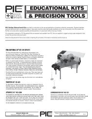
PRECISION RUBBER ROLLERS<br />
IDLER ROLLERS<br />
55 DUROMETER SHORE A<br />
DRIVE ROLLERS<br />
55 DUROMETER SHORE A<br />
MATERIAL: Neoprene (Urethane, 40-90 Shore A Durometer<br />
optionally available)<br />
Clear Anodized Aluminum Hub<br />
RS6-0500-3<br />
RS5-0625-3<br />
RS6-0750-4<br />
RS6-0875-4<br />
RS8-1000-4<br />
RS8-1125-4<br />
RS8-1525-6<br />
RS10-2000-6<br />
(2) #8-32<br />
RD4-0625-3<br />
RD6-0750-4<br />
RD6-0875-4<br />
RD3-1000-3<br />
RD8-1000-4<br />
RD6-1125-4<br />
RD8-1625-6<br />
RD10-2000-6<br />
www.pic-design.com<br />
Interactive catalog ■ CAD ■ e-commerce<br />
DESIGN<br />
®<br />
Phone: 800-243-6125 ■ FAX: 203-758-8271<br />
E-Mail: sales@pic-design.com<br />
4-15