improving wearable slot antenna performance with ebg ... - Taconic
improving wearable slot antenna performance with ebg ... - Taconic
improving wearable slot antenna performance with ebg ... - Taconic

You also want an ePaper? Increase the reach of your titles
YUMPU automatically turns print PDFs into web optimized ePapers that Google loves.
2008 Loughborough Antennas & Propagation Conference 17-18 March 2008, Loughborough, UK<br />
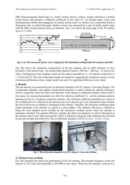
EBG (Electromagnetic Band Gap) is a nearly lossless reactive surface, usually realized as a printed<br />
circuit board, that presents a reflection coefficient of the order of 1 to incident plane waves and<br />
simultaneously inhibits the propagation of surface current across its surface over a prescribed band of<br />
frequencies (the so-called band gap). Surface current was measured by a pair of small current loops<br />
<strong>with</strong> the EBG structure placed above an absorber. Fig. 2 (a) shows the band edge of the TE surface<br />
wave is 3.2 GHz.<br />
<strong>slot</strong> <strong>antenna</strong><br />
S21(dB)<br />
-20<br />
1 1.5 2 2.5 3 3.5 4<br />
-30<br />
-40<br />
-50<br />
Band Edge<br />
-60<br />
-70<br />
-80<br />
-90<br />
Frequency (GHz)<br />
ε = 42, µ = 1, σ = 2 Lossy medium<br />
r<br />
EBG<br />
r<br />
300mm<br />
h=1mm foam<br />
H=1mm foam<br />
25mm<br />
(a)<br />
(b)<br />
Fig. 2: (a) The measured surface wave coupling (b) The Simulation configuration for <strong>antenna</strong> and EBG<br />
Fig. 2(b) shows the simulation configuration of the <strong>slot</strong> <strong>antenna</strong> <strong>with</strong> an EBG substrate in close<br />
proximity to the human body. The human body phantom model is 300 mm × 200 mm × 25 mm in size<br />
<strong>with</strong> a homogeneous lossy medium which has the relative permittivity ε<br />
r<br />
=42 and the conductivity σ<br />
= 2.0 S/m [6] [7]. The size of this body model was found by comparing the simulation results in terms<br />
of <strong>antenna</strong> <strong>performance</strong> when a larger model was used. No significant differences were found.<br />
3. Results<br />
The <strong>slot</strong> <strong>antenna</strong> was measured in the reverberation chamber in ECIT, Queen’s University Belfast. The<br />
reverberation chamber, also called a mode-stirred chamber is used to obtain the <strong>antenna</strong> efficiency,<br />
which is especially useful for body worn <strong>antenna</strong>s. In the design of traditional <strong>antenna</strong>s which work in<br />
free space, the measured parameters are often the reflection coefficient S 11<br />
and the radiation patterns<br />
measured in the E or H planes around the <strong>antenna</strong>. The reflection coefficient describes how much of<br />
the available power is reflected at the <strong>antenna</strong> port, but it does not give any information about whether<br />
the rest of the power is radiated or dissipated in the <strong>antenna</strong>. Therefore, the reflection coefficient alone<br />
cannot determine if the <strong>antenna</strong> is a good or a poor radiator. The radiation efficiency is defined as<br />
being the total radiated power divided by the maximum available power when the <strong>antenna</strong> is<br />
impedance matched. The <strong>antenna</strong> efficiency includes the effects of mismatch, as well as absorption in<br />
the <strong>antenna</strong> and its near field environment, which is defined as being the total radiated power divided<br />
by the total incident power[8]-[10]. The reverberation chamber in ECIT is 2.4 m × 2.4 m × 2.4 m.<br />
Lossy Phantom<br />
Slot<br />
<strong>antenna</strong><br />
EBG<br />
Fig. 3: Reverberation chamber in ECIT, Queen’s University Belfast<br />
3.1 Return Loss on Body<br />
Fig. 4(a) examines the return loss <strong>performance</strong> of the <strong>slot</strong> <strong>antenna</strong>. The resonant frequency of the <strong>slot</strong><br />
<strong>antenna</strong> is 2.85 GHz, the bandwidth is 350 MHz in free space. When the <strong>slot</strong> <strong>antenna</strong> is placed on a<br />
174