The TSM-DS - Taconic
The TSM-DS - Taconic
The TSM-DS - Taconic

Create successful ePaper yourself
Turn your PDF publications into a flip-book with our unique Google optimized e-Paper software.
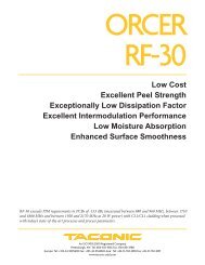
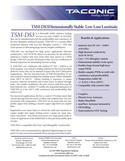
<strong>TSM</strong>-<strong>DS</strong>3<strong>TSM</strong>-<strong>DS</strong>3Dimensionally Stable Low Loss Laminateis a thermally stable, industry leadinglow loss core (Df = 0.0011 at 10 GHz)that can be manufactured with the predictability and consistency ofthe best fiberglass reinforced epoxies. <strong>TSM</strong>-<strong>DS</strong>3 is a ceramic-filledreinforced material with very low fiberglass content (~ 5%) thatrivals epoxies in fabricating large format complex multilayers.<strong>TSM</strong>-<strong>DS</strong>3 was developed for high power applications (thermalconductivity = 0.65 W/M*K) where it is necessary for the dielectricmaterial to conduct heat away from other heat sources in a PWBdesign. <strong>TSM</strong>-<strong>DS</strong>3 was also developed to have very low coefficients ofthermal expansion for demanding thermal cycling.A <strong>TSM</strong>-<strong>DS</strong>3 core combined with fastRise27 (Df = 0.0014 at 10GHz) prepreg is an industry leading solution for the lowest possibledielectric losses that can be attained at epoxy-like 420˚F fabricationtemperatures. <strong>The</strong> low insertion losses of <strong>TSM</strong>-<strong>DS</strong>3/fastRise27 areonly rivaled by fusion bonding (the melting of pure Teflon® laminatesfrom 550˚F to 650˚F). Fusion bonding is expensive, it causesexcessive material movement and it puts stress on plated throughholes. For complex multilayers, the price of poor yield drives up thefinal material cost. fastRise27 enables the sequential lamination of<strong>TSM</strong>-<strong>DS</strong>3 at a low 420˚F with consistency and predictability thatreduces cost.For microwave applications, the low x, y and z CTE values assure thatcritical spacings between traces in filters and couplers have very lowmovement with temperature. <strong>TSM</strong>-<strong>DS</strong>3 can be used with very lowprofile copper foils yielding a smooth copper edge between coupledlines.Registration over many layers is critical for yield and variations incopper weight and copper etching across a panel can cause nonlinearmovement. Non-linear movement over large panels leads toa lack of registration of the drilled hole to the pad and possibly opencircuits.<strong>TSM</strong>-<strong>DS</strong>3 is compatible with Ticer® and OhmegaPly® resistive foils.<strong>TSM</strong>-<strong>DS</strong>3 is not recommended for tight pitch digital designs (≤ 1 mmpitch). It is also not recommended for lines and spaces less than 4 mils).Benefits & Applications:• Industry best Df (Df = 0.0011@10 GHz)• High thermal conductivity(0.65 W/M*K)• Low (~5%) fiberglass content• Dimensional stability rivals epoxy• Enables large format high layercount PWBs• Builds complex PWBs in yield withconsistency and predictability• Temperature stable Dk+/- 0.25% (-30 to 120ºC)• Compatible with resistive foils• Couplers• Phased Array Antennas• Radar Manifolds• mmWave Antenna/Automotive• Oil Drilling• Semiconductor/ATE TestingNorth & South America<strong>Taconic</strong> - HeadquartersPetersburgh, NY 12138Tel: 518-658-3202 / 1-800-833-1805addinfo@4taconic.comEurope/Middle East/Australia<strong>Taconic</strong> International Ltd.Republic of IrelandTel: +353-44-9395600add@4taconic.comAsiaKorea <strong>Taconic</strong> CompanyRepublic of KoreaTel: +82-31-704-1858sales@taconic.co.krAn ISO 9001 Registered Companywww.taconic-add.comCommercial and Government Entity (CAGE) Code: 1C6Q9China<strong>Taconic</strong> Advanced Material (Suzhou) Co., Ltd.Suzhou City, ChinaTel: +86-512-8718-9678tssales@taconic.co.kr
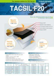
<strong>TSM</strong>-<strong>DS</strong>3 Dimensionally Stable Low Loss LaminateHFSS Simulation of 50 ohm microstrip to stripline via transitionGood Registration Around PadsReturn Loss (dB)<strong>The</strong> HFSS simulation above conceptually shows the degraded performance of a 50 ohm microstrip to striplinetransmission line with poor via registration.RF designers have known for many years that registration affects the insertion loss/return loss of RF transmissionlines using a stripline design. Poor via transitions cripple high frequency stripline designs over 10 GHz resultingin discontinuities from the targeted 50 or 100 ohms.Signal performance is related to:• <strong>The</strong> number and spacing of ground vias• <strong>The</strong> size of ground via pads• <strong>The</strong> distance from the drilled signal via pad to the ground vias• <strong>The</strong> alignment of the drilled via to the center of the pad<strong>The</strong> following factors affect poor registration:• Movement of the material core after etching and lamination• Drill wander• Prepreg flow• Scaling factors, pinning techniques and non-linear movement
<strong>TSM</strong>-<strong>DS</strong>3 Dimensionally Stable Low Loss LaminateRing Resonator Properties vs. Frequency on<strong>TSM</strong>-<strong>DS</strong>3-0010. (Test set up as shown on page 4).<strong>The</strong> <strong>TSM</strong>-<strong>DS</strong>3 dielectric constant shows a+/- 0.2% deviation with temperature.DkDf (tan δ)Frequency (GHz)<strong>The</strong> dissipation factor varies from 0.0007 -0.0011 over a typical application temperaturerange.Insertion loss comparison of <strong>TSM</strong>-<strong>DS</strong>3vs. a synthetic rubber hydrocarbonlaminate.Test vehicle shown below usingSouthwest Connectors.<strong>TSM</strong>-<strong>DS</strong>3 (Dk = 3.0)Dielectric 5 milsTrace Width = 12 milsINSERTION LOSS - Loss Per InchItem 30 GHz 57 GHz 67 GHz-1.0380dB -2.386 dB -2.861 dBInsertion Loss (dB) - <strong>TSM</strong>-<strong>DS</strong>3Synthetic Rubber Hydrocarbon(Dk=3.38)Dielectric 8 milsTrace Width = 17 mils-2.023 dB -3.553 dB -4.150 dB
<strong>TSM</strong>-<strong>DS</strong>3 Dimensionally Stable Low Loss Laminate<strong>TSM</strong>-<strong>DS</strong>3 is especially suited for couplers and filters where the coupler spacing is affected by temperatureextremes. <strong>The</strong> low x-y CTE values of 10/16 (x/y) ppm/°C assure good control over the spacing betweencoupled lines in an edge coupler or a band pass filter. <strong>The</strong> low z axis CTE of 23 ppm/°C (RT to 125 °C) assuresa low increase in dielectric thickness in a broadside coupler.Scaling Factors X (mils/inch) Y (mils/inch)Scaling Factors(<strong>TSM</strong>-<strong>DS</strong>3)Industry Standard Epoxy, 10 mil core 0.4 - 0.5* 0.4 - 0.5*<strong>TSM</strong>-<strong>DS</strong>3, 10 mil core < 0.4* < 0.4*Industry Standard Epoxy, 5 mil core ~ 1.0 ~ 1.0<strong>TSM</strong>-<strong>DS</strong>3, 5 mil core ~ 1.0 ~ 1.0*As measured by Harbor ElectronicsDimensional movement as measured byan x-ray for multilayer drilling registration(Harbor Electronics)
<strong>TSM</strong>-<strong>DS</strong>3 Typical ValuesProperty Test Method Unit Value Unit ValueDk @ 10 GHz IPC-650 2.5.5.5.1 (Modified) 3.00 3.00T cK (-30 to 120 °C) IPC-650 2.5.5.5.1 (Modified) ppm 5.4 ppm 5.4Df @ 10 GHz IPC-650 2.5.5.5.1 (Modified) 0.0011 0.0011Dielectric Breakdown IPC-650 2.5.6 (ASTM D 149) kV 47.5 kV 47.5Dielectric Strength ASTM D 149 (Through Plane) V/mil 548 V/mm 21,575Arc Resistance IPC-650 2.5.1 Seconds 226 Seconds 226Moisture Absorption IPC-650 2.6.2.1 % 0.07 % 0.07Flexural Strength (MD) ASTM D 790/ IPC-650 2.4.4 psi 11,811 N/mm 2 81Flexural Strength (CD) ASTM D 790/ IPC-650 2.4.4 psi 7,512 N/mm 2 51Tensile Strength (MD) ASTM D 3039/IPC-650 2.4.19 psi 7,030 N/mm 2 48Tensile Strength (CD) ASTM D 3039/IPC-650 2.4.19 psi 3,830 N/mm 2 26Elongation at Break (MD) ASTM D 3039/IPC-650 2.4.19 % 1.6 % 1.6Elongation at Break (CD) ASTM D 3039/IPC-650 2.4.19 % 1.5 % 1.5Young’s Modulus (MD) ASTM D 3039/IPC-650 2.4.19 psi 973,000 N/mm 2 6,708Young’s Modulus (CD) ASTM D 3039/IPC-650 2.4.19 psi 984,000 N/mm 2 6,784Poisson’s Ratio (MD) ASTM D 3039/IPC-650 2.4.19 0.24 0.24Poisson’s Ratio (CD) ASTM D 3039/IPC-650 2.4.19 0.20 0.20Compressive Modulus ASTM D 695 (23°C) psi 310,000 N/mm 2 2,137Flexural Modulus (MD) ASTM D 790/IPC-650 2.4.4 kpsi 1,860 N/mm 2 12,824Flexural Modulus (CD) ASTM D 790/IPC-650 2.4.4 kpsi 1,740 N/mm 2 11,996Peel Strength (CV1) IPC-650 2.4.8 Sec 5.2.2 (TS) lbs/in 8 N/mm 1.46<strong>The</strong>rmal Conductivity (unclad) ASTM F 433/ASTM 1530-06 W/M*K 0.65 W/M*K 0.65Dimensional Stability (MD) IPC-650 2.4.39 Sec. 5.4 (After Bake) mils/in. 0.21 mm/M 0.21Dimensional Stability (CD) IPC-650 2.4.39 Sec. 5.4 (After Bake) mils/in. 0.20 mm/M 0.20Dimensional Stability (MD) IPC-650 2.4.39 Sec. 5.5 (TS) mils/in. 0.15 mm/M 0.15Dimensional Stability (CD) IPC-650 2.4.39 Sec. 5.5 (TS) mils/in. 0.10 mm/M 0.10Surface Resistivity IPC-650 2.5.17.1 Sec. 5.2.1 (ET) Mohms 2.3 x 10 6 Mohms 2.3 x 10 6Surface Resistivity IPC-650 2.5.17.1 Sec. 5.2.1 (HC) Mohms 2.1 x 10 7 Mohms 2.1 x 10 7Volume Resistivity IPC-650 2.5.17.1 Sec. 5.2.1 (ET) Mohms/cm 1.1 x 10 7 Mohms/cm 1.1 x 10 7Volume Resistivity IPC-650 2.5.17.1 Sec. 5.2.1 (HC) Mohms/cm 1.8 x 10 8 Mohms/cm 1.8 x 10 8CTE (x axis) (RT to 125ºC) IPC-650 2.4.41/TMA ppm/ºC 10 ppm/ºC 10CTE (y axis) (RT to 125ºC) IPC-650 2.4.41/TMA ppm/ºC 16 ppm/ºC 16CTE (z axis) (RT to 125ºC) IPC-650 2.4.41/TMA ppm/ºC 23 ppm/ºC 23Density (Specific Gravity) ASTM D 792 g/cm 3 2.11 g/cm 3 2.11Hardness ASTM D 2240 (Shore D) 79 79T d(2% Weight Loss) IPC-650 2.4.24.6 (TGA) ºC 526 ºC 526T d(5% Weight Loss) IPC-650 2.4.24.6 (TGA) ºC 551 ºC 551ET - Elevated TemperatureHC - Humidity ConditioningTS - <strong>The</strong>rmal Stress<strong>TSM</strong>-<strong>DS</strong>3 is not recommended for tight pitch digital designs (≤ 1 mm pitch). It is also not recommended for lines and spaces less than 4 mils.All reported values are typical and should not be used for specification purposes. In all instances, the user shall determine suitability in any givenapplication.
<strong>TSM</strong>-<strong>DS</strong>3 Dimensionally Stable Low Loss LaminateDesignationDk<strong>TSM</strong>-<strong>DS</strong>3 3.0 +/-0.05Typical Thicknesses *Inchesmm0.0050, 0.0100, 0.0200 0.13, 0.25, 0.510.0300, 0.0600, 0.0900 0.76, 1.52, 2.29*Other thicknesses in increments of 5 mils availableupon request.Available Sheet SizesInches mm12 x 18 304 x 45716 x 18 406 x 45718 x 24 457 x 61016 x 36 406 x 91424 x 36 610 x 91418 x 48 457 x 1220CopperDesignationSurface Roughness R MSTreated sideAvailable Copper CladdingSurface Roughness R MSUntreated sideDescriptionThicknessMicroinches Microns Microinches Microns Mils MicronsRH 12 0.3 12 0.3 Rolled-Annealed ½ oz 0.7 17.5R1 10 0.3 7 0.2 Rolled-Annealed 1 oz 1.4 35.0CFH 19 0.5 14 0.35 Electrodeposited ½ oz 0.7 17.5CF1 12 0.32 13 0.33 Electrodeposited 1 oz 1.4 35.0CLH 13 0.3 20 0.5CL1 13 0.3 25 0.6CVH (CH) 27 0.7 11 0.3CV1 (C1) 25 0.6 11 0.3Reverse TreatedElectrodeposited ½ ozReverse TreatedElectrodeposited 1 ozVery Low ProfileElectrodeposited ½ ozVery Low ProfileElectrodeposited 1 oz0.7 17.51.4 35.00.7 17.51.4 35.0C2 77 2.0 8 0.2 Electrodeposited 2 oz 2.8 70.0Measurememt Instrument and Captured ResultsAgilent E8364A PNA Network Analyzer and Universal test fixture 3830 K (by ANRITSU) were used for ring resonator testing.An example of our part number is: <strong>TSM</strong>-<strong>DS</strong>3-0050-CV1/CV1 - 18" x 24" (457 mm x 610 mm)rev. 5/13