improving wearable slot antenna performance with ebg ... - Taconic
improving wearable slot antenna performance with ebg ... - Taconic
improving wearable slot antenna performance with ebg ... - Taconic

You also want an ePaper? Increase the reach of your titles
YUMPU automatically turns print PDFs into web optimized ePapers that Google loves.
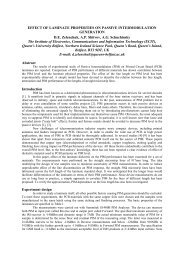
2008 Loughborough Antennas & Propagation Conference 17-18 March 2008, Loughborough, UK<br />
IMPROVING WEARABLE SLOT ANTENNA PERFORMANCE WITH EBG<br />
STRUCTURES<br />
Z. Duan, D. Linton, W. Scanlon, G. Conway<br />
The Institute of Electronics, Communications and Information Technology (ECIT)<br />
Queen’s University Belfast, Queen’s Road, Queen’s Island, Belfast, UK, BT3 9DT<br />
Email: zduan01@ecit.qub.ac.uk, d.linton@ee.qub.ac.uk<br />
Abstract: This paper presents a 2.8GHz <strong>slot</strong> <strong>antenna</strong> over an EBG (Electromagnetic Band Gap)<br />
substrate <strong>with</strong> the objective of higher <strong>antenna</strong> efficiency, wide bandwidth and compact operation in<br />
close proximity to the human body. To achieve compact size, two different size EBGs are developed<br />
and the <strong>antenna</strong> return loss and efficiency are measured in a reverberation chamber. From these results,<br />
the EBG substrate demonstrates 60% improvement of the <strong>antenna</strong> efficiency compared to other<br />
methods in the <strong>wearable</strong> <strong>antenna</strong> scenario.<br />
1. Introduction<br />
Wireless networks for body worn applications need small efficient <strong>antenna</strong>s when working near the<br />
human body. Because of the effects on <strong>antenna</strong>s in close proximity to the human body, such as<br />
resonant frequency shifts, radiation pattern fragmentation and signal absorption; body worn <strong>antenna</strong>s<br />
have recently received much attention [1]. Novel micro strip <strong>antenna</strong>s and EBG substrates were<br />
investigated to reduce or eliminate signal radiation in the area of the user, thus reducing signal<br />
absorption in tissue. Also because of its low profile structure, the micro strip patch <strong>antenna</strong> is a<br />
promising candidate for body worn applications [2] [3].<br />
A copper wire <strong>antenna</strong> built on an EBG surface is described in [4] that is designed for the form factor<br />
of a portable handset. Measurements carried out for the radiation pattern show high radiation<br />
efficiency near the center of the band gap <strong>with</strong>out taking the <strong>antenna</strong> return loss into account. In this<br />
paper, we propose a 2.8 GHz <strong>slot</strong> <strong>antenna</strong> over an EBG substrate capable of providing total <strong>antenna</strong><br />
efficiency around 76% in proximity to the human body and directly obtain the <strong>antenna</strong> efficiency in a<br />
reverberation chamber. For comparison, we work out the <strong>slot</strong> <strong>antenna</strong> <strong>performance</strong> <strong>with</strong>out EBG and<br />
<strong>with</strong> PEC (Perfect Electric Conductor) in proximity to the human body.<br />
2. Antenna and EBG structure<br />
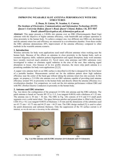
Fig. 1(a) shows the configuration of the proposed 2.8 GHz <strong>slot</strong> <strong>antenna</strong> and the EBG substrate. The<br />
patch <strong>antenna</strong> is based on <strong>Taconic</strong> RF-35 (ε r =3.5, Loss tangent=0.0018) <strong>with</strong> a thickness of 1.52 mm.<br />
The <strong>antenna</strong> size is 30 mm × 36 mm. The EBG in Fig. 1(b) consists of 6×6 and 4×4 small patch<br />
segments over a solid metal sheet. The space between patches and ground plane is filled <strong>with</strong> <strong>Taconic</strong><br />
CER-10 (ε r =10, Loss tangent=0.0035) of thickness 3.18 mm and the dimensions of the substrates used<br />
are 63.75 mm × 63.75 mm and 44.25 mm × 44.25 mm. The EBG design method [5] is used to select<br />
the patch dimensions and substrate thickness. Only the suppression of the TE surface current is of<br />
interest, so we do not use a via-array in the substrate.<br />
9mm<br />
(a)<br />
(b)<br />
Fig. 1 (a) Slot <strong>antenna</strong> and (b) EBG structure (6×6 elements and 4×4 elements)<br />
978-1-4244-1894-7/08/$25.00 ©2008 IEEE<br />
173
2008 Loughborough Antennas & Propagation Conference 17-18 March 2008, Loughborough, UK<br />
EBG (Electromagnetic Band Gap) is a nearly lossless reactive surface, usually realized as a printed<br />
circuit board, that presents a reflection coefficient of the order of 1 to incident plane waves and<br />
simultaneously inhibits the propagation of surface current across its surface over a prescribed band of<br />
frequencies (the so-called band gap). Surface current was measured by a pair of small current loops<br />
<strong>with</strong> the EBG structure placed above an absorber. Fig. 2 (a) shows the band edge of the TE surface<br />
wave is 3.2 GHz.<br />
<strong>slot</strong> <strong>antenna</strong><br />
S21(dB)<br />
-20<br />
1 1.5 2 2.5 3 3.5 4<br />
-30<br />
-40<br />
-50<br />
Band Edge<br />
-60<br />
-70<br />
-80<br />
-90<br />
Frequency (GHz)<br />
ε = 42, µ = 1, σ = 2 Lossy medium<br />
r<br />
EBG<br />
r<br />
300mm<br />
h=1mm foam<br />
H=1mm foam<br />
25mm<br />
(a)<br />
(b)<br />
Fig. 2: (a) The measured surface wave coupling (b) The Simulation configuration for <strong>antenna</strong> and EBG<br />
Fig. 2(b) shows the simulation configuration of the <strong>slot</strong> <strong>antenna</strong> <strong>with</strong> an EBG substrate in close<br />
proximity to the human body. The human body phantom model is 300 mm × 200 mm × 25 mm in size<br />
<strong>with</strong> a homogeneous lossy medium which has the relative permittivity ε<br />
r<br />
=42 and the conductivity σ<br />
= 2.0 S/m [6] [7]. The size of this body model was found by comparing the simulation results in terms<br />
of <strong>antenna</strong> <strong>performance</strong> when a larger model was used. No significant differences were found.<br />
3. Results<br />
The <strong>slot</strong> <strong>antenna</strong> was measured in the reverberation chamber in ECIT, Queen’s University Belfast. The<br />
reverberation chamber, also called a mode-stirred chamber is used to obtain the <strong>antenna</strong> efficiency,<br />
which is especially useful for body worn <strong>antenna</strong>s. In the design of traditional <strong>antenna</strong>s which work in<br />
free space, the measured parameters are often the reflection coefficient S 11<br />
and the radiation patterns<br />
measured in the E or H planes around the <strong>antenna</strong>. The reflection coefficient describes how much of<br />
the available power is reflected at the <strong>antenna</strong> port, but it does not give any information about whether<br />
the rest of the power is radiated or dissipated in the <strong>antenna</strong>. Therefore, the reflection coefficient alone<br />
cannot determine if the <strong>antenna</strong> is a good or a poor radiator. The radiation efficiency is defined as<br />
being the total radiated power divided by the maximum available power when the <strong>antenna</strong> is<br />
impedance matched. The <strong>antenna</strong> efficiency includes the effects of mismatch, as well as absorption in<br />
the <strong>antenna</strong> and its near field environment, which is defined as being the total radiated power divided<br />
by the total incident power[8]-[10]. The reverberation chamber in ECIT is 2.4 m × 2.4 m × 2.4 m.<br />
Lossy Phantom<br />
Slot<br />
<strong>antenna</strong><br />
EBG<br />
Fig. 3: Reverberation chamber in ECIT, Queen’s University Belfast<br />
3.1 Return Loss on Body<br />
Fig. 4(a) examines the return loss <strong>performance</strong> of the <strong>slot</strong> <strong>antenna</strong>. The resonant frequency of the <strong>slot</strong><br />
<strong>antenna</strong> is 2.85 GHz, the bandwidth is 350 MHz in free space. When the <strong>slot</strong> <strong>antenna</strong> is placed on a<br />
174
2008 Loughborough Antennas & Propagation Conference 17-18 March 2008, Loughborough, UK<br />
phantom, the resonant frequency is around 2.75 GHz by the detuning effect. When the EBG structure<br />
<strong>antenna</strong> is placed on the phantom, the resonant frequency stays at 2.85 GHz, the bandwidth decreases<br />
to 100 MHz, which is caused by the strong coupling effect by only a 1 mm separation between the <strong>slot</strong><br />
<strong>antenna</strong> and the EBG surface. (EBG6 means the EBG structure <strong>with</strong> 6×6 elements and EBG4 for 4×4<br />
elements). For comparison we placed a PEC reflector instead of the EBG and in this case there is no<br />
apparent resonant frequency and S<br />
11<br />
is above -10dB from 2.6 GHz to 3.2 GHz.<br />
3.2 Efficiency and Radiation Pattern<br />
As signal absorption occurs in close proximity to the human body, the <strong>antenna</strong> efficiency has become<br />
the key parameter in our design. Fig. 4 indicates the <strong>antenna</strong> efficiency in different scenarios. As<br />
illustrated in Fig. 4, the <strong>slot</strong> <strong>antenna</strong> in free space has an efficiency of η a = 95%while <strong>with</strong> the <strong>antenna</strong><br />
5 mm away from the human body, the efficiency becomes η a = 16% and η a = 10% <strong>with</strong> a PEC<br />
reflector. However, when an EBG is applied under the <strong>slot</strong> <strong>antenna</strong>, the <strong>antenna</strong> efficiency is η a = 76%<br />
for a 6×6 element EBG and 67% for a 4×4 element EBG which has a 50%-60% improvement<br />
compared to the <strong>antenna</strong> <strong>with</strong>out EBG. The improvements arise from the characteristic of in-phase<br />
reflection and surface wave suppression thus it effectively isolates the <strong>slot</strong> <strong>antenna</strong> from the<br />
surrounding environments.<br />
Return Loss(dB)<br />
0<br />
2.6 2.7 2.8 2.9 3 3.1 3.2<br />
-5<br />
-10<br />
-15<br />
-20<br />
-25<br />
-30<br />
-35<br />
-40<br />
Frequency(GHZ)<br />
Free space<br />
Phantom<br />
EBG6+Phantom<br />
EBG4+Phantom<br />
PEC+Phantom<br />
Antenna Efficiency<br />
1<br />
0.9<br />
0.8<br />
0.7<br />
0.6<br />
0.5<br />
0.4<br />
0.3<br />
0.2<br />
0.1<br />
0<br />
free space<br />
Phantom<br />
EBG6+Phantom<br />
EBG4+Phantom<br />
PEC+Phantom<br />
2.6 2.7 2.8 2.9 3 3.1 3.2<br />
Frequency(GHz)<br />
(a)<br />
Fig. 4 (a) Measured Return Loss from 2.6 to 3.2 GHz (b) Measured Antenna Efficiency from 2.6 to 3.2<br />
GHz<br />
(b)<br />
(a) (b) (c)<br />
Fig. 5 Simulated Radiation Pattern (a) free space (b) On Phantom w/o EBG (c) On Phantom w EBG<br />
3.3 The separation effect between the <strong>antenna</strong> and EBG surface<br />
In previous experiments, we set the gap h between the <strong>slot</strong> <strong>antenna</strong> to the EBG surface to be 1mm<br />
which makes sure the whole structure is more compact. To indicate the separation effect, we adjust the<br />
gap h between 2 mm and 3 mm. The simulation (h=*mm_S) and measurement (h=*mm_M) results<br />
are shown in Fig. 6.<br />
175
2008 Loughborough Antennas & Propagation Conference 17-18 March 2008, Loughborough, UK<br />
0<br />
2.6 2.7 2.8 2.9 3 3.1 3.2<br />
-5<br />
Table 1: Measured Bandwidth and Max. Antenna<br />
Efficiency<br />
Return Loss (dB)<br />
-10<br />
-15<br />
-20<br />
-25<br />
-30<br />
-35<br />
h 1 mm 2 mm 3 mm<br />
Bandwidth 103 202 318<br />
(MHz)<br />
Max. Antenna<br />
Efficiency<br />
76% 73% 71%<br />
-40<br />
h= 1mm_S h=2mm_S h=3mm_S<br />
h= 1mm_M h=2mm_M h=3mm_M<br />
-45<br />
Frequency (GHz)<br />
Fig. 6 Measured and Simulated Return Loss at given h<br />
The <strong>antenna</strong> efficiency is shown in Table 1. The efficiency decreases around 2-3% when h is increased<br />
by 1 mm, this is <strong>with</strong>in the quoted error (0.5dB) for the reverberation chamber. Nonetheless the<br />
difference may be attributed to the EBG in-phase reflection feature. The <strong>slot</strong> <strong>antenna</strong> radiates a linear<br />
polarized wave to the EBG surface, the phase difference of the reflection field from the EBG surface<br />
to the incident E field is larger when h becomes larger, in that the <strong>antenna</strong> efficiency decreases from<br />
76% down to 71%.<br />
4. Conclusions<br />
An EBG surface for <strong>improving</strong> the <strong>antenna</strong> efficiency in a <strong>wearable</strong> scenario has been proposed. We<br />
have selected two different size EBGs to compare their <strong>performance</strong> as the target for compact<br />
operation. By changing the proposed design h, we can discover how the centre resonant frequencies<br />
shift and bandwidth increases. For our future work, we are <strong>improving</strong> our structure to obtain a higher<br />
efficiency, wider bandwidth and compact design simultaneously.<br />
Reference<br />
[1] Peter S. Yang hao, “Antennas and propagation for body-centric wireless communications”, Boston,<br />
Mass. London, Artech House, ISBN 978-1-580-53493-2, 2006.<br />
[2] K.L.Wong and C.I.Lin, "Characteristics of a 2.4-GHz compact shorted patch <strong>antenna</strong> in close to a<br />
lossy medium," Microwave Opt. Technol. Lett., vol. 45, pp. 480-483, 2005.<br />
[3] D. Sievenpiper, L. Zhang, R. F. J. Broas, N. G. Alexopolous and E. Yablonovitch, "Highimpedance<br />
electromagnetic surfaces <strong>with</strong> a forbidden frequency band," IEEE Trans. Microwave<br />
Theory Tech., vol. 47, pp. 2059-74, 11. 1999.<br />
[4] R. F. J. Broas, D. F. Sievenpiper and E. Yablonovitch, "A High-Impedance Ground Plane Applied<br />
to a Cellphone Handset Geometry," IEEE Trans. on Microwave Theory Tech, vol. 49, pp 1262-65, 7<br />
2001.<br />
[5] S. Clavijo, R. E. Diaz and W. E. McKinzie III, "Design methodology for Sievenpiper highimpedance<br />
surfaces: an artificial magnetic conductor for positive gain electrically small <strong>antenna</strong>s,"<br />
IEEE Transactions on Antennas and Propagation, vol. 51, pp. 2678-90, 10. 2003.<br />
[6] A. Christ, A. Klingenbock, T. Samaras, C. Goiceanu and N. Kuster, "The dependence of<br />
electromagnetic far-field absorption on body tissue composition in the frequency range from 300 MHz<br />
to 6 GHz," IEEE Trans. Microwave Theory Tech., vol. 54, pp. 2188-95, 05. 2006.<br />
[7] http://niremf.ifac.cnr.it/tissprop/<br />
[8] http://www.bluetest.se/method.html<br />
[9] U. Carlberg, P-S. Kildal, A. Wolfgang, O. Sotoudeh, C. Orlenius, “Calculated and measured<br />
absorption cross sections of lossy objects in reverberation chamber”, IEEE Transactions on<br />
Electromagnetic Compatibility, Vol. 46 No. 2, pp.146-154, 05. 2004.<br />
[10] N.K. Kouveliotis,P.T. Trakadas,I.I. Heretakis,C.N. Capsalis, “Antenna Reverberation Chamber”,<br />
Encyclopaedia of RF and Microwave Engineering, Volumes 1 – 6, pp239-251, John Wiley & Sons,<br />
2005.<br />
176