Experiment 5 Addressing modes, CALL , RET , XLAT , Stack , Arrays ...
Experiment 5 Addressing modes, CALL , RET , XLAT , Stack , Arrays ...
Experiment 5 Addressing modes, CALL , RET , XLAT , Stack , Arrays ...

Create successful ePaper yourself
Turn your PDF publications into a flip-book with our unique Google optimized e-Paper software.
MICROPROCESSOR AND INTERFACING LAB<br />
DEPARTMENT OF ELECTRICAL AND ELECTRONIC<br />
ENGINEERING, BUET<br />
<strong>Experiment</strong> 5<br />
<strong>Addressing</strong> <strong>modes</strong>, <strong>CALL</strong> , <strong>RET</strong> , <strong>XLAT</strong> , <strong>Stack</strong> , <strong>Arrays</strong><br />
5.1 Objective<br />
The objective of this experiment are<br />
To learn the basic ideas of addressing <strong>modes</strong>: accessing variables and array elements,<br />
To get familiarized with procedures and stack: <strong>CALL</strong> and <strong>RET</strong> instructions, and<br />
To understand the <strong>XLAT</strong> instruction.<br />
5.2 Address Arithmetic<br />
5.2.1 <strong>Arrays</strong><br />
<strong>Arrays</strong> allow us to refer to a collection of similar data by a single name and individual items in the<br />
collection with the name and a numeric subscript. An array of 4 bytes might be declared as<br />
Now if we write<br />
Arr DB 0BH , 1BH , 2BH , 3BH<br />
MOV AL , Arr +3 ; sets AL to 3BH<br />
MOV AL , [Arr + 3] ; sets AL to 3BH<br />
Suppose the following arrays are defined<br />
A DB 0Ah , 1Ah , 2Ah , 3Ah , 4Ah , 5Ah<br />
B DB 0Bh , 1Bh , 2Bh , 3Bh<br />
C DB 0Ch , 1Ch<br />
Then the following instructions have the results given:<br />
MOV AL , [B+3] ; sets AL = 3Bh<br />
MOV AL , [B+4] ; sets AL = 0Ch<br />
MOV AL , [A+12] ; sets AL = 1Ch<br />
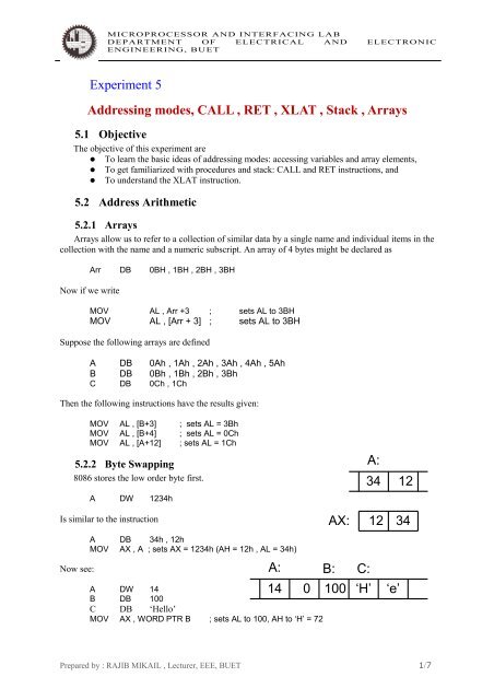
5.2.2 Byte Swapping<br />
8086 stores the low order byte first.<br />
A DW 1234h<br />
Is similar to the instruction<br />
Now see:<br />
A DB 34h , 12h<br />
MOV AX , A ; sets AX = 1234h (AH = 12h , AL = 34h)<br />
A:<br />
14 0<br />
A DW 14<br />
B DB 100<br />
C DB ‘Hello’<br />
MOV AX , WORD PTR B ; sets AL to 100, AH to ‘H’ = 72<br />
AX:<br />
B:<br />
100<br />
A:<br />
34 12<br />
12 34<br />
C:<br />
‘H’ ‘e’<br />
Prepared by : RAJIB MIKAIL , Lecturer, EEE, BUET 1/7
MICROPROCESSOR AND INTERFACING LAB<br />
DEPARTMENT OF ELECTRICAL AND ELECTRONIC<br />
ENGINEERING, BUET<br />
5.2.3 Examples and applications<br />
Example 1:<br />
CODE SEGMENT<br />
ASSUME CS: CODE , DS: CODE<br />
; sets up an array of 10 words , with each initialized by 9<br />
; Here we shall copy W to Z and set W[N] = 0 for N = 0 to 9<br />
ORG 100H<br />
MOV CX , 10<br />
MOV DI , 0 ; N = 0<br />
Zero:<br />
MOV AX , [W + DI]<br />
MOV [Z + DI] , AX<br />
MOV [W + DI] , 0 ; W[N] = 0<br />
ADD DI , 2 ; N = N + 1<br />
DEC CX<br />
JNZ Zero<br />
HLT<br />
ORG 150H<br />
W DW 10 DUP (9) ; Creates an array of 10 words initialized by 9 each<br />
; Note : DUP came for duplicate.<br />
Z DW 10 DUP() ; Creates an array of 10 uninitialized words<br />
CODE ENDS<br />
END<br />
Example 2:<br />
CODE SEGMENT<br />
ASSUME CS: CODE , DS: CODE<br />
; convert all lowercase letters in the array to the corresponding uppercase letters<br />
;<br />
ORG 100H<br />
MOV SI , OFFSET B<br />
Upcase:<br />
MOV AL , [SI]<br />
CMP AL , ‘$’<br />
JE DONE<br />
CMP AL , ‘a’<br />
JB NotLC<br />
CMP AL , ‘z’<br />
JA NotLC<br />
ADD BYTE PTR [SI] , ‘A’ - ‘a’<br />
NotLC:<br />
INC SI<br />
JNZ Upcase<br />
DONE:<br />
HLT<br />
B DB ‘HelLo’ , ‘$’<br />
CODE ENDS<br />
END<br />
Example 3:<br />
; This program generates the average marks of students’ class test<br />
CODE SEGMENT<br />
Prepared by : RAJIB MIKAIL , Lecturer, EEE, BUET 2/7
MICROPROCESSOR AND INTERFACING LAB<br />
DEPARTMENT OF ELECTRICAL AND ELECTRONIC<br />
ENGINEERING, BUET<br />
ASSUME CS: CODE , DS: CODE<br />
ORG 100H<br />
MOV AX , CS<br />
MOV DS , AX<br />
MOV SI , 3<br />
REPEAT:<br />
MOV CX , 4<br />
XOR BX , BX<br />
XOR AX , AX<br />
FOR:<br />
MOV DL , MARK[BX + SI] ; Based Indexed <strong>Addressing</strong> mode<br />
; Note: as we want to take one byte contents from the<br />
; memory location MARK[BX + SI] the destination must be<br />
; also an one byte register<br />
MOV DH , 0<br />
ADD AX , DX ; accumulating the summation in AX<br />
ADD BL , 4<br />
LOOP FOR<br />
; end of FOR<br />
XOR DX , DX<br />
DIV FOUR ; Here AH will contain the remainder and AL the result<br />
MOV AVG[SI] , AL<br />
SUB SI , 1<br />
JNL REPEAT<br />
DONE:<br />
HLT<br />
FOUR DB 4<br />
;Class Test Mark: T1 : T2 : T3 : T4 : Name<br />
;------------------------------------------------<br />
MARK DB 15 , 20 , 12 , 16 ; Shajib<br />
DB 14 , 10 , 18 , 20 ; Imran<br />
DB 12 , 15 , 20 , 17 ; Akash<br />
DB 14 , 17 , 16 , 11 ; Maisha<br />
AVG DB 4 DUP (0)<br />
CODE ENDS<br />
END<br />
5.3 Procedures<br />
5.3.1 <strong>CALL</strong><br />
To invoke a procedure, the <strong>CALL</strong> instruction is used. Executing a <strong>CALL</strong> instruction causes the<br />
following to happen:<br />
1. The return address to the calling program is saved on the stack. This is the offset of the next<br />
instruction after the <strong>CALL</strong> statement.<br />
2. IP gets the offset address of the first instruction of the procedure.<br />
5.3.2 <strong>RET</strong><br />
To return from a procedure the instruction<br />
<strong>RET</strong> pop_value<br />
is executed. The integer argument pop_value is optional. After executing <strong>RET</strong> the value at the stack is<br />
stored into IP. Remember this value was previously stored in the stack when we called the procedure<br />
Prepared by : RAJIB MIKAIL , Lecturer, EEE, BUET 3/7
MICROPROCESSOR AND INTERFACING LAB<br />
DEPARTMENT OF ELECTRICAL AND ELECTRONIC<br />
ENGINEERING, BUET<br />
and this is the address of the next instruction of the <strong>CALL</strong> statement. If a pop_value is specified, it is<br />
added to SP after performing the previous action ( the value in the stack to IP).<br />
5.3.3 Examples And Applications<br />
Example : 4<br />
;First follow the code in the box.<br />
;If you face problem to find the logic of the<br />
;code below then keep it for home.<br />
CODE SEGMENT<br />
ASSUME CS:CODE,DS:CODE<br />
ORG 100H<br />
MOV AX,3<br />
PUSH AX<br />
<strong>CALL</strong> FACT<br />
; AX CONTAINS THE FACTORIAL OF<br />
AX<br />
HLT<br />
FACT:<br />
PUSH BP<br />
MOV BP,SP<br />
IF:<br />
CMP WORD PTR[BP+4],1<br />
JG ENDIF<br />
THEN:<br />
MOV AX,1<br />
JMP <strong>RET</strong>URN<br />
ENDIF:<br />
MOV CX,[BP + 4]<br />
DEC CX<br />
PUSH CX<br />
<strong>CALL</strong> FACT<br />
MUL WORD PTR[BP+4]<br />
<strong>RET</strong>URN:<br />
POP BP<br />
<strong>RET</strong> 2<br />
CODE ENDS<br />
END<br />
; increments the<br />
stack pointer (SP) by<br />
4. Here 2 increament<br />
is for<br />
CODE SEGMENT<br />
ASSUME CS:CODE,DS:CODE<br />
ORG 100H<br />
MOV AX,3<br />
PUSH AX<br />
<strong>CALL</strong> FACT<br />
; AX CONTAINS THE FACTORIAL OF AX<br />
HLT<br />
FACT:<br />
PUSH BP<br />
MOV BP,SP<br />
IF:<br />
CMP WORD PTR[BP+4],1<br />
JG ENDIF<br />
THEN:<br />
MOV AX,1<br />
POP BP<br />
JMP <strong>RET</strong>URN<br />
ENDIF:<br />
MOV CX,[BP + 4]<br />
DEC CX<br />
PUSH CX<br />
<strong>CALL</strong> FACT<br />
MUL WORD PTR[BP+4]<br />
POP CX<br />
POP BP<br />
<strong>RET</strong>URN:<br />
<strong>RET</strong><br />
CODE ENDS<br />
END<br />
; popping the stack top to IP and the remaining 2 is that is specified after ; the <strong>RET</strong><br />
instruction.<br />
The instruction in the box do the same operation. But here we have equal number of PUSH and POP<br />
instructions. The program flow itself maintain the value of stack pointer through PUSH POP instruction. If we<br />
have not the same number of PUSH and POP then we have think about the stack. And we may need to insert<br />
value after the <strong>RET</strong> instruction.<br />
Prepared by : RAJIB MIKAIL , Lecturer, EEE, BUET 4/7
MICROPROCESSOR AND INTERFACING LAB<br />
DEPARTMENT OF ELECTRICAL AND ELECTRONIC<br />
ENGINEERING, BUET<br />
For clear understanding the change in stack during the program is shown below:<br />
Address<br />
Content<br />
BP assigned to<br />
SP third time<br />
BP assigned to<br />
SP second time<br />
BP assigned to<br />
SP first time<br />
First position of SP <br />
FFEC :<br />
FFEE :<br />
FFF0 :<br />
FFF2 :<br />
FFF4 :<br />
FFF6 :<br />
FFF8 :<br />
FFFA :<br />
FFFC :<br />
FFFE :<br />
F2<br />
FF<br />
1E<br />
00<br />
01<br />
00<br />
F8<br />
FF<br />
1E<br />
00<br />
02<br />
00<br />
00<br />
00<br />
07<br />
00<br />
03<br />
00<br />
00<br />
FF<br />
STACK<br />
PUSH BP<br />
Next offset value of<br />
third call of FACT<br />
PUSH CX<br />
PUSH BP<br />
Next offset value of<br />
second call of FACT<br />
PUSH CX<br />
PUSH BP<br />
Next offset value of<br />
first call of FACT<br />
PUSH AX<br />
5.4 <strong>XLAT</strong><br />
The instruction <strong>XLAT</strong> (translate) is a no-operand instruction that can be used to convert a byte<br />
value into another value that comes from a table. The byte to be converted must be in AL, and the<br />
offset address of the conversion table must be in BX. The instruction does :<br />
Step 1. Adds the contents in AL to the address in BX to produce an address within the table.<br />
Step 2. Replaces the contents of AL by the value found at that address.<br />
5.4.1 Examples And Applications<br />
Example: 5<br />
; To read a secret message<br />
CODE SEGMENT<br />
ASSUME CS: CODE, DS: CODE<br />
;<br />
ORG 100H<br />
Prepared by : RAJIB MIKAIL , Lecturer, EEE, BUET 5/7
MICROPROCESSOR AND INTERFACING LAB<br />
DEPARTMENT OF ELECTRICAL AND ELECTRONIC<br />
ENGINEERING, BUET<br />
LEA BX,ENCRYPT ; LEA stands for Load Effective Address.<br />
LEA SI,ORIGINAL<br />
LEA DI,ENCODED<br />
; To convert a message into encrypted version<br />
NCRPT:<br />
MOV AL,[SI]<br />
CMP AL,'$'<br />
JE END1<br />
<strong>XLAT</strong><br />
MOV [DI],AL<br />
INC DI<br />
INC SI<br />
JMP NCRPT<br />
END1:<br />
MOV [DI],AL<br />
;To decrypt the encrypted message<br />
LEA BX,DECRYPT<br />
LEA SI,ENCODED<br />
LEA DI,DECODED<br />
DCRPT:<br />
MOV AL,[SI]<br />
CMP AL,'$'<br />
JE END2<br />
<strong>XLAT</strong><br />
MOV [DI],AL<br />
INC DI<br />
INC SI<br />
JMP DCRPT<br />
END2:<br />
MOV [DI],AL<br />
;End of decryption<br />
HLT<br />
; ALPHABET 'ABCDEFGHIJKLMNOPQRSTUVWXYZ'<br />
ENCRYPT DB 65 DUP (' '), 'XQPOGHZBCADEIJUVFMNKLRSTWY' ; one space in the bracket<br />
DB 37 DUP (' ') ; Think ! why the 65 blank spaces placed first.<br />
; ALPHABET 'ABCDEFGHIJKLMNOPQRSTUVWXYZ'<br />
DECRYPT DB 65 DUP (' '), 'JHIKLQEFMNTURSDCBVWXOPYAZG'<br />
DB 37 DUP (' ')<br />
ORIGINAL DB 'GATHER YOUR FORCES AND ATTACK' , 30 DUP ('$')<br />
ENCODED DB 80 DUP ('$')<br />
DECODED DB 80 DUP ('$')<br />
;<br />
CODE ENDS<br />
END<br />
Go to the offset address 0131H for original message , offset address 016CH for encoded message and<br />
offset address 01BCH for decoded message. Use your own message and verify to those addresses<br />
after running.<br />
Home Task:<br />
• Make a program that will sort an array content descending order and ascending order and put<br />
in another arrays. First of all describe the algorithm you want to implement.<br />
• Write an algorithm to convert a binary number into decimal and implement it in assembly<br />
language.<br />
• Find out the DECRIPT sequence for the ENCRIPT sequence of :<br />
Prepared by : RAJIB MIKAIL , Lecturer, EEE, BUET 6/7
MICROPROCESSOR AND INTERFACING LAB<br />
DEPARTMENT OF ELECTRICAL AND ELECTRONIC<br />
ENGINEERING, BUET<br />
‘QWERTYUIOPASDFGHJKLZXCVBNM’<br />
And rewrite the last program to detect any secret message according to the upper encryption.<br />
Date: 7 - 7 - 7<br />
Prepared by : RAJIB MIKAIL , Lecturer, EEE, BUET 7/7