h Technical Product Data Gravity Pipe Systems PN 1 - Hobas
h Technical Product Data Gravity Pipe Systems PN 1 - Hobas
h Technical Product Data Gravity Pipe Systems PN 1 - Hobas

You also want an ePaper? Increase the reach of your titles
YUMPU automatically turns print PDFs into web optimized ePapers that Google loves.
h<br />
<strong>Technical</strong> <strong>Product</strong> <strong>Data</strong><br />
<strong>Gravity</strong> <strong>Pipe</strong> <strong>Systems</strong> <strong>PN</strong> 1
© E Engineering GmbH<br />
All rights reserved.<br />
Responsible for content: Stefan Scheiflinger, Manuela Wendt, Wilfried Sieweke<br />
Layout: Benjamin Angerer, Alexandra Dobnigg<br />
Publication: 11/2010 | Update: 05/2012 | Print: Carinthian Druck Beteiligungs GmbH 05/2012<br />
All rights reserved. No part of this document may be reproduced or utilized in any form or by any means without our prior written per-<br />
mission. All information in the document is correct at the time of going to press. However, we reserve the right to make changes without<br />
notice, in particular to technical data. The data given is not binding and must therefore be checked in each individual case and revised as<br />
appropriate.
○ Sewer systems<br />
○<br />
○ Relining of circular pipe systems<br />
○<br />
○ Relining of non circular pipe systems<br />
○<br />
○ ○<br />
○ Reconstruction of industry systems<br />
○<br />
Features and advantages<br />
○<br />
○<br />
○<br />
○<br />
○<br />
○<br />
○<br />
○<br />
○<br />
○<br />
○<br />
○<br />
○<br />
○<br />
○<br />
low weight and simple coupling technology decrease laying time<br />
homogenous wall structure through to patent registered centrifugal process<br />
high abrasion resistance<br />
low incrustations and sludge precipitations<br />
very smooth inner surface (roughness ≤ 0.01 mm)<br />
no sensitivity to frost and high temperatures (duroplaste characteristics)<br />
very low expansion coefficient<br />
high UV resistance<br />
high loading capactiy<br />
very good performance in chemical resistance<br />
long life time<br />
deflection in coupling is possible<br />
laying is not dependent on weather conditions<br />
Air pipe systems<br />
Shafts and manholes<br />
Bridge lines<br />
Drinking water tanks<br />
numerous fittings available including shafts and manholes (seamless), inside and outside layer have high resistance<br />
simple handling<br />
HOBAS <strong>Gravity</strong> <strong>Pipe</strong> <strong>Systems</strong><br />
Wide spread field of applications<br />
Whether for sewage disposal, retaining channels, drainage lines or industrial applications: HOBAS <strong>Pipe</strong> <strong>Systems</strong> made of<br />
glass fiber reinforced plastic (GRP) are used around the world in many different areas. The roots of the composite material<br />
technology can be found in the automotive, aerospace and shipbuilding industry; HOBAS has been producing GRP pipes<br />
since the 1950s. The composite material was further developed over the years and is today available for complex challenges<br />
in the following applications:<br />
Field of applications:<br />
Trenchless jacking Retention systems
B1 de to product standard (EN 1796/EN 14364)<br />
B2 de<br />
B3 de<br />
B4 de<br />
BL<br />
DC<br />
de<br />
DEC<br />
DN<br />
e<br />
FWC<br />
GRP<br />
L<br />
LC<br />
m<br />
n<br />
DN Th<br />
p max<br />
<strong>PN</strong><br />
PVC<br />
R<br />
SN<br />
α<br />
Length<br />
Glass reinforced plastic (glass fiber reinforced, unsaturated polyester resin)<br />
Nominal pressure<br />
Polyvinyl chloride<br />
Radius<br />
to GRP and casting standards<br />
to GRP and PVC standards<br />
to GRP and steel standards<br />
GRP coupling with sealing rings<br />
<strong>Pipe</strong> external diameter<br />
Coupling external diameter<br />
Nominal diameter<br />
<strong>Pipe</strong> wall thickness<br />
GRP coupling with full width EPDM gasket (A...asymmetric, S…symmetric)<br />
Length<br />
Coupling length<br />
Mass<br />
Number<br />
Theoretical diameter<br />
Maximum operating pressure<br />
Nominal stiffness<br />
Angle (bend, deflection)
PIPES<br />
PIPE JOINTS<br />
FITTINGS<br />
ACCESSORIES MANHOLES<br />
A01<br />
A01<br />
A02<br />
A03<br />
A03<br />
A04<br />
A05<br />
A05<br />
A05<br />
A05<br />
A05<br />
A05<br />
B01<br />
B02<br />
C01<br />
C01<br />
C02<br />
C02<br />
C02<br />
C03<br />
C03<br />
C04<br />
C04<br />
C05<br />
C05<br />
C06<br />
C07<br />
C08<br />
C09<br />
D01<br />
D02<br />
E01<br />
E01<br />
E02<br />
E03<br />
E03<br />
F01<br />
Non-Pressure <strong>Pipe</strong>s DN 150 - 1000<br />
Non-Pressure <strong>Pipe</strong>s DN 1100 - 3600<br />
Double <strong>Pipe</strong>s<br />
Relining <strong>Pipe</strong>s DN 750 - 1500<br />
Relining <strong>Pipe</strong>s DN 1535 - 3600<br />
NC Line - Extract<br />
Jacking <strong>Pipe</strong>s de 272 - 501<br />
Jacking <strong>Pipe</strong>s de 530 - 752<br />
Jacking <strong>Pipe</strong>s de 820 - 1099<br />
Jacking <strong>Pipe</strong>s de 1229 - 1535<br />
Jacking <strong>Pipe</strong>s de 1638 - 2160<br />
Jacking <strong>Pipe</strong>s de 2250 - 3600<br />
Standard <strong>Pipe</strong> Joints<br />
Special Couplings<br />
Bends DN 150 - 1000<br />
Bends DN 1100 - 3600<br />
T-Piece DN 150 - 800<br />
T-Piece DN 150 - 800<br />
T-Piece DN 900 - 1600<br />
Y-Piece DN 150 - 700<br />
Y-Piece DN 800 - 1600<br />
Saddle - glued DN 200 - 400<br />
Saddle - glued DN 500 - 1600<br />
Saddle- screwed DN 300 -700<br />
Saddle- screwed DN 700 - 1200<br />
Reducers<br />
Flange with GRP/Steel Loose Flange<br />
GRP Fixed Flange<br />
Blind flange from GRP and steel<br />
Standard Manhole DN 1000 - 3600<br />
Tangential Manhole DN 1000 - 3600<br />
Masonry Coupling DN 150 - 1000<br />
Masonry Coupling DN 1100 - 3600<br />
Manhole Liner<br />
Structural Adapters DN 150 - 1000<br />
Structural Adapters DN 1100 - 3600<br />
Material <strong>Data</strong>
DN<br />
Diameter series<br />
Non-Pressure <strong>Pipe</strong>s DN 150 - 1000<br />
The standard length of the <strong>Pipe</strong> is 6 m. Lengths of 1 / 2 / 3 m are available on request.<br />
SN 2500 SN 5000 SN 10000 SN 15000 SN 16000 SN 20000<br />
de m e m e m e m e m e m e<br />
[mm] [kg/m] [mm] [kg/m] [mm] [kg/m] [mm] [kg/m] [mm] [kg/m] [mm] [kg/m] [mm]<br />
150 B2 168 5 5 6 6 6 6 6 6<br />
200 B2 220 8 7 9 7 10 7 10 8<br />
250 B2 272 13 8 14 9 14 9 15 9<br />
300 B2 B4 324 18 9 20 10 20 10 21 11<br />
350 B2 376 15 7 19 8 24 10 26 11 27 12 29 12<br />
400 B3 401 17 7 21 9 26 11 29 12 30 12 32 13<br />
400 B2 427 19 8 24 9 30 11 33 13 34 13 36 14<br />
450 B2 478 22 8 27 9 34 11 38 13 39 13 42 14<br />
500 B3 501 24 8 30 10 37 12 42 13 43 14 46 14<br />
500 B2 530 27 8 33 10 41 12 47 14 48 14 51 15<br />
550 - 550 29 9 36 11 45 13 51 15 52 15 55 16<br />
600 B1 616 36 10 45 12 56 14 63 16 64 17 69 18<br />
650 - 650 40 10 50 12 62 15 70 17 72 17 76 19<br />
700 B1 718 48 11 60 13 75 17 85 19 87 19 93 20<br />
750 - 752 53 11 66 14 82 17 93 19 95 20 102 21<br />
800 B1 820 63 12 78 15 98 19 110 21 113 21 120 23<br />
860 - 860 69 13 86 16 107 19 121 22 124 22 132 24<br />
900 B1 924 79 14 99 17 124 21 139 23 142 24 152 26<br />
960 - 960 86 14 107 18 133 22 150 24 153 25 164 27<br />
1000 B1 1026 98 15 122 19 151 23 171 26 174 26 187 28<br />
Wall thicknesses and masses as guidelines (plus tolerances)<br />
The standard length is 6 m (+0/-60 mm). Some pipes can also be supplied in shorter lengths depending on availability.<br />
All figures quoted are values and may slightly vary due to manufacturing tolerances. The information and recommendations reflect the state of our knowledge at the time of publication/update. Therefore the provided data cannot be construed as an express or implied warranty. All details must<br />
be checked and if necessary agreed to in each individual case. HOBAS cannot accept any liability. This also applies to errors, omissions and changes to technical data without notice.<br />
A01<br />
NON-PRESSURE PIPES
DN<br />
Diameter series<br />
Non-Pressure <strong>Pipe</strong>s DN 1100 - 3600<br />
The standard length of the <strong>Pipe</strong> is 6 m. Lengths of 1 / 2 / 3 m are available on request.<br />
de m e m e m e m e m e m e<br />
[mm] [kg/m] [mm] [kg/m] [mm] [kg/m] [mm] [kg/m] [mm] [kg/m] [mm] [kg/m] [mm]<br />
1100 - 1099 112 16 141 20 175 25 196 28 201 28 215 30<br />
1200 B1 1229 140 18 174 22 216 27 244 31 249 31 267 34<br />
1280 - 1280 152 19 189 23 236 28 265 32 270 33 289 35<br />
1350 - 1350 169 20 210 24 262 30 294 34 300 34 321 37<br />
1400 B1 1434 190 21 237 26 294 32 331 36 338 36 362 39<br />
1500 - 1499 208 21 258 27 322 33 362 37 368 38 395 41<br />
1535 - 1535 220 22 274 27 340 34 382 38 389 39 418 42<br />
1600 B1 1638 249 23 312 29 387 36 434 41 443 41 475 44<br />
1720 - 1720 274 25 343 31 425 38 478 42 491 44 522 46<br />
1800 B1 1842 314 26 393 33 487 40 547 45 559 46 599 50<br />
1940 - 1940 346 27 434 34 538 42 609 48 621 49 661 52<br />
2000 B1 2047 386 29 484 36 600 45 675 50 688 51 738 55<br />
2160 - 2160 432 31 539 38 667 47 750 53 765 54 821 58<br />
2200 B1 2250 465 31 584 39 723 49 813 55 836 56 890 60<br />
2400 - 2400 533 34 665 42 823 52 926 59 945 60 1012 64<br />
2400 B1 2454 557 35 694 43 860 53 968 60 987 61 1059 66<br />
2555 - 2555 604 36 752 45 932 55 1048 62 1069 64 1147 68<br />
2740 - 2740 693 40 865 50 1070 61 1212 69 1237 71 1317 75<br />
3000 - 3000 829 42 1033 52 1281 65 1440 73 1469 74 1575 80<br />
3600 - 3600 1189 50 1485 62 1840 77 2085 88 2127 89 2265 95<br />
Wall thicknesses and masses as guidelines (plus tolerances)<br />
SN 2500 SN 5000 SN 10000 SN 15000 SN 16000 SN 20000<br />
The standard length is 6 m (+0/-60 mm). Some pipes can also be supplied in shorter lengths depending on availability.<br />
All figures quoted are values and may slightly vary due to manufacturing tolerances. The information and recommendations reflect the state of our knowledge at the time of publication/update. Therefore the provided data cannot be construed as an express or implied warranty. All details must<br />
be checked and if necessary agreed to in each individual case. HOBAS cannot accept any liability. This also applies to errors, omissions and changes to technical data without notice.<br />
A01<br />
NON-PRESSURE PIPES
Double <strong>Pipe</strong>s<br />
HOBAS <strong>Pipe</strong>s can be used as pipe-in-pipe systems in such applications as drinking water protection areas or thermally<br />
insulated bridge drainage. Possible combinations are given in the table. For technical details, designs available and<br />
recommendations for installation, please contact your HOBAS Consultant. The standard length of the <strong>Pipe</strong> is 6 m. Lengths<br />
of 1 / 2 / 3 m are available on request.<br />
Double <strong>Pipe</strong><br />
Outside diameter<br />
Coupling outside<br />
diameter<br />
Outside diameter<br />
Coupling outside<br />
diameter<br />
de1 DEC1 de2 DEC2<br />
[mm] [mm] [mm] [mm]<br />
200/300 220 260 324 360<br />
250/350 272 310 376 420<br />
300/400 324 360 427 470<br />
350/450 376 420 478 520<br />
400/500 427 470 530 580<br />
500/600 530 580 616 660<br />
600/700 616 660 718 760<br />
700/800 718 760 820 870<br />
800/900 820 870 924 970<br />
900/1000 924 970 1026 1070<br />
1000/1200 1026 1070 1099 1140<br />
1100/1200 1099 1140 1229 1270<br />
1200/1400 1229 1270 1434 1480<br />
1250/1400 1280 1330 1434 1480<br />
1350/1500 1350 1390 1499 1540<br />
1400/1600 1434 1480 1638 1680<br />
1500/1600 1499 1540 1638 1680<br />
1500/1700 1535 1580 1720 1770<br />
1600/1800 1638 1680 1842 1890<br />
1700/1900 1720 1770 1940 1990<br />
1800/2000 1842 1890 2047 2090<br />
Wall thicknesses and weights as guidelines (plus tolerances)<br />
Media pipe (SN 10000) Casing pipe (SN 10000)<br />
The standard length is 6 m (+0/-60 mm). Some pipes can also be supplied in shorter lengths depending on availability.<br />
All figures quoted are values and may slightly vary due to manufacturing tolerances. The information and recommendations reflect the state of our knowledge at the time of publication/update. Therefore the provided data cannot be construed as an express or implied warranty. All details must<br />
be checked and if necessary agreed to in each individual case. HOBAS cannot accept any liability. This also applies to errors, omissions and changes to technical data without notice.<br />
A02<br />
NON-PRESSURE PIPES
Relining <strong>Pipe</strong>s DN 750 - 1500<br />
Relining pipes are available with flush couplings. As alternative, Relining pipes are also available as standard pipes with<br />
FWC couplings (see A01). The standard length of the <strong>Pipe</strong> is 6 m. Lengths of 1 / 2 / 3 m are available on request.<br />
Allowable insertion force for pipes with flush couplings:<br />
DN de Coupling m e F* m e F* m e F* m e F*<br />
[mm] [kg/m] [mm] [kN] [kg/m] [mm] [kN] [kg/m] [mm] [kN] [kg/m] [mm] [kN]<br />
750 752 stainless steel 106 20 1142<br />
800 820 stainless steel 127 21 1428<br />
860 860 stainless steel 139 23 1756<br />
900 924 GRP 161 25 1641<br />
900 924 stainless steel 161 25 2042<br />
960 960 GRP 174 26 1795<br />
960 960 stainless steel 174 26 2265<br />
1000 1026 GRP 193 28 2238<br />
1000 1026 stainless steel 180 23 1938 193 28 2726<br />
1100 1099 GRP 207 27 2097 221 30 2600<br />
1100 1099 stainless steel 185 23 2063 207 27 2740 221 30 3245<br />
1200 1229 GRP 257 30 2709 281 34 3460<br />
1200 1229 stainless steel 224 25 2677 257 30 3625 281 34 4377<br />
1280 1280 GRP 284 32 3117 301 36 3899<br />
1280 1280 stainless steel 242 27 3197 284 32 4183 301 36 4965<br />
1350 1350 GRP 309 34 3600 335 37 4218<br />
1350 1350 stainless steel 273 30 4053 309 34 4882 335 37 5501<br />
1400 1434 GRP 310 32 3238 348 36 4119 376 39 4776<br />
1400 1434 stainless steel 253 26 3383 310 32 4716 348 36 5598 376 39 6256<br />
1500 1499 GRP 334 33 3525 383 38 4675 413 41 5362<br />
1500 1499 stainless steel 275 27 3643 334 33 5037 383 38 6190 413 41 6878<br />
Wall thicknesses and pipe masses as minimum or guidelines (plus tolerances)<br />
SN 5000 SN 10000 SN 16000<br />
SN 20000<br />
* The allowable insertion force implies a safety factor of 1.75 of the maximum force calculated<br />
All figures quoted are values and may slightly vary due to manufacturing tolerances. The information and recommendations reflect the state of our knowledge at the time of publication/update. Therefore the provided data cannot be construed as an express or implied warranty. All details must<br />
be checked and if necessary agreed to in each individual case. HOBAS cannot accept any liability. This also applies to errors, omissions and changes to technical data without notice.<br />
A03<br />
NON-PRESSURE PIPES
DN de Coupling m e F* m e F* m e F* m e F*<br />
[mm] [kg/m] [mm] [kN] [kg/m] [mm] [kN] [kg/m] [mm] [kN] [kg/m] [mm] [kN]<br />
1535 1535 GRP 282 27 2142 353 34 3809 404 39 4990 434 42 5695<br />
1535 1535 stainless steel 282 27 2413 353 34 4083 404 39 5266 434 42 5971<br />
1600 1638 GRP 322 29 2665 398 36 4440 452 41 5698 484 44 6448<br />
1600 1638 stainless steel 322 29 3134 398 36 4910 452 41 6169 484 44 6921<br />
1720 1720 GRP 361 31 2444 441 38 4307 509 44 5890 531 46 6415<br />
1720 1720 stainless steel 361 31 3805 441 38 5668 509 44 7253 531 46 7779<br />
1800 1842 GRP 412 33 3112 498 40 5108 571 46 6807 619 50 7933<br />
1800 1842 stainless steel 412 33 4658 498 40 6657 571 46 8358 619 50 9485<br />
1940 1940 GRP 447 34 2321 550 42 4726 639 49 6814 677 52 7704<br />
1940 1940 stainless steel 447 34 5166 550 42 7572 639 49 9659 677 52 10549<br />
2000 2047 GRP 500 36 4004 622 45 6855 703 51 8742 756 55 9993<br />
2000 2047 stainless steel 500 36 6097 622 45 8951 703 51 10840 756 55 12093<br />
2160 2160 GRP 556 38 4107 685 47 7123 785 54 9443 841 58 10764<br />
2160 2160 stainless steel 556 38 7393 685 47 10405 785 54 12729 841 58 14050<br />
2200 2250 GRP 595 39 4934 745 49 8419 848 56 10840 907 60 12216<br />
2200 2250 stainless steel 595 39 7794 745 49 11283 848 56 13706 907 60 15083<br />
2400 2400 GRP 683 42 6008 842 52 9722 968 60 12669 1031 64 14135<br />
2400 2454 GRP 716 43 6345 879 53 10148 1008 61 13167 1089 66 15043<br />
2555 2555 GRP 780 45 7206 949 55 11165 1101 64 14700 1168 68 16263<br />
2740 2740 GRP 912 49 8989 1148 62 14509 1275 69 17458 1400 76 20392<br />
3000 3000 GRP 1059 52 6806 1318 65 12850 1495 74 17002 1613 80 19756<br />
3600**<br />
Wall thicknesses and pipe masses as minimum or guidelines (plus tolerances)<br />
* The allowable insertion force implies a safety factor of 1.75 of the maximum force calculated<br />
** On request<br />
Relining <strong>Pipe</strong>s DN 1535 - 3600<br />
Relining pipes are available with flush couplings. As alternative, Relining pipes are also available as standard pipes with<br />
FWC couplings (see A01). The standard length of the <strong>Pipe</strong> is 6 m. Lengths of 1 / 2 / 3 m are available on request.<br />
Allowable insertion force for pipes with flush couplings:<br />
SN 5000 SN 10000 SN 16000 SN 20000<br />
All figures quoted are values and may slightly vary due to manufacturing tolerances. The information and recommendations reflect the state of our knowledge at the time of publication/update. Therefore the provided data cannot be construed as an express or implied warranty. All details must<br />
be checked and if necessary agreed to in each individual case. HOBAS cannot accept any liability. This also applies to errors, omissions and changes to technical data without notice.<br />
A03<br />
NON-PRESSURE PIPES
DN DN Th* A BL DN DN Th* A BL<br />
B/H [mm] [m²] [m] B/H [mm] [m²] [m]<br />
1600/1600 1600 2,011 3,0 1360/1570 1469 1,596 2,0<br />
1800/1800 1798 2,539 3,0 2680/2590 2618 5,170 2,3<br />
DN DN Th* A BL DN DN Th* A BL<br />
B/H [mm] [m²] [m] B/H [mm] [m²] [m]<br />
480/800 649 0,290 2,5 300/500 409 0,120 2,5<br />
510/810 672 0,320 2,5 400/600 505 0,180 2,5<br />
400/1000 752 0,310 2,5 500/750 632 0,290 2,5<br />
750/1500 1182 0,920 2,5 600/900 757 0,410 2,5<br />
1100/1400 1271 1,220 3,0 680/1050 873 0,540 3,0<br />
1080/1650 1375 1,350 2,5 800/1200 1010 0,740 2,5<br />
1600/1800 1721 2,310 2,5 900/1350 1136 0,930 2,5<br />
* theoretical diameter<br />
NC Line - Extract<br />
Other shapes available on request.<br />
1000/1500 1262 1,150 2,5<br />
1200/1800 1515 1,650 3,0<br />
1400/2100 1767 2,250 3,0<br />
Extract from the range of non-circular cross-sections that can be supplied for rehabilitation and new installations to<br />
customer specifications<br />
All figures quoted are values and may slightly vary due to manufacturing tolerances. The information and recommendations reflect the state of our knowledge at the time of publication/update. Therefore the provided data cannot be construed as an express or implied warranty. All details must<br />
be checked and if necessary agreed to in each individual case. HOBAS cannot accept any liability. This also applies to errors, omissions and changes to technical data without notice.<br />
A04<br />
NON-PRESSURE PIPES
Jacking <strong>Pipe</strong>s de 272 - 501<br />
GRP jacking pipes with flush coupling (GRP or stainless steel) - allowable jacking forces. The standard length of the<br />
<strong>Pipe</strong> is 6 m. Lengths of 1 / 2 / 3 m are available on request.<br />
de [mm] SN SN SN SN SN SN SN SN SN SN SN SN<br />
Coupling 32000 40000 50000 64000 80000 100000 128000 160000 200000 320000 640000 1000000<br />
272 e [mm] 19 24<br />
m [kg/m] 33 41<br />
stainless steel F [kN]* 204 297<br />
324 e [mm] 20 23 28<br />
m [kg/m] 42 48 57<br />
stainless steel F [kN]* 273 341 452<br />
376 e [mm] 19 20 23 27 32<br />
m [kg/m] 47 49 56 65 76<br />
stainless steel F [kN]* 297 324 405 424 638<br />
401 e [mm] 19 20 21 24 28 34 39<br />
m [kg/m] 50 53 55 62 72 86 97<br />
stainless steel F [kN]* 315 344 373 459 572 736 868<br />
GRP F [kN]* 647 779<br />
427 e [mm] 19 20 21 24 28 34 39<br />
m [kg/m] 54 56 59 67 77 92 105<br />
stainless steel F [kN]* 342 373 405 497 618 795 938<br />
GRP F [kN]* 696 839<br />
478 e [mm] 21 23 25 27 29 33 41 46<br />
m [kg/m] 66 72 78 84 90 101 124 137<br />
stainless steel F [kN]* 449 519 588 657 725 859 1120 1278<br />
GRP F [kN]* 1015 1173<br />
501 e [mm] 20 22 24 26 28 30 35 43 48<br />
m [kg/m] 66 73 79 85 91 98 113 136 150<br />
stainless steel F [kN]* 434 509 582 655 727 798 974 1247 1412<br />
GRP F [kN]* 864 1137 1302<br />
Wall thicknesses and pipe masses as minimum or guidelines plus tolerances to HOBAS Company Standard.<br />
* The allowable jacking force (kN) corresponds to a safety factor of 3.5 times against the ultimate force calculated. Static calculation of specific<br />
projects can result in differing allowable jacking forces.<br />
All figures quoted are values and may slightly vary due to manufacturing tolerances. The information and recommendations reflect the state of our knowledge at the time of publication/update. Therefore the provided data cannot be construed as an express or implied warranty. All details must<br />
be checked and if necessary agreed to in each individual case. HOBAS cannot accept any liability. This also applies to errors, omissions and changes to technical data without notice.<br />
A05<br />
NON-PRESSURE PIPES
Jacking <strong>Pipe</strong>s de 530 - 752<br />
GRP jacking pipes with flush coupling (GRP or stainless steel) - allowable jacking forces. The standard length of the<br />
<strong>Pipe</strong> is 6 m. Lengths of 1 / 2 / 3 m are available on request.<br />
de [mm] SN SN SN SN SN SN SN SN SN SN SN SN<br />
Coupling 32000 40000 50000 64000 80000 100000 128000 160000 200000 320000 640000 1000000<br />
530 e [mm] 20 23 24 26 28 31 36 44 51<br />
m [kg/m] 70 81 84 90 97 107 123 148 169<br />
stainless steel F [kN]* 459 577 616 694 770 885 1071 1362 1608<br />
GRP F [kN]* 957 1247 1492<br />
550 e [mm] 20 21 22 24 26 28 30 33 38 47 53<br />
m [kg/m] 73 75 80 87 94 101 108 118 134 163 182<br />
stainless steel F [kN]* 484 505 566 648 728 808 888 1006 1199 1537 1755<br />
GRP F [kN]* 893 1086 1423 1640<br />
616 e [mm] 21 23 25 27 29 32 34 37 43 50 58<br />
m [kg/m] 86 94 102 110 118 129 137 148 170 196 224<br />
stainless steel F [kN]* 583 675 767 858 949 1083 1172 1304 1564 1860 2188<br />
GRP F [kN]* 1040 1172 1432 1727 2055<br />
650 e [mm] 21 24 25 26 28 30 33 35 38 44 54 62<br />
m [kg/m] 91 104 108 112 120 128 141 149 161 184 222 252<br />
stainless steel F [kN]* 613 760 809 857 953 1049 1191 1285 1425 1700 2146 2491<br />
GRP F [kN]* 1055 1148 1288 1563 2008 2352<br />
718 e [mm] 23 25 27 28 30 32 35 40 43 48 59 68<br />
m [kg/m] 110 120 129 134 143 152 165 187 201 222 269 305<br />
stainless steel F [kN]* 733 842 949 1003 1109 1215 1373 1633 1787 2040 2583 3012<br />
GRP F [kN]* 1121 1278 1538 1691 1944 2486 2915<br />
752 e [mm] 24 26 28 30 33 36 39 42 45 51 62 72<br />
m [kg/m] 121 130 140 150 164 178 192 206 220 247 296 338<br />
stainless steel F [kN]* 800 913 1026 1138 1305 1470 1634 1797 1958 2276 2843 3342<br />
GRP F [kN]* 1231 1396 1560 1722 1882 2199 2765 3263<br />
Wall thicknesses and pipe masses as minimum or guidelines plus tolerances to HOBAS Company Standard.<br />
* The allowable jacking force (kN) corresponds to a safety factor of 3.5 times against the ultimate force calculated. Static calculation of specific<br />
projects can result in differing allowable jacking forces.<br />
All figures quoted are values and may slightly vary due to manufacturing tolerances. The information and recommendations reflect the state of our knowledge at the time of publication/update. Therefore the provided data cannot be construed as an express or implied warranty. All details must<br />
be checked and if necessary agreed to in each individual case. HOBAS cannot accept any liability. This also applies to errors, omissions and changes to technical data without notice.<br />
A05<br />
NON-PRESSURE PIPES
Jacking <strong>Pipe</strong>s de 820 - 1099<br />
GRP jacking pipes with flush coupling (GRP or stainless steel) - allowable jacking forces. The standard length of the<br />
<strong>Pipe</strong> is 6 m. Lengths of 1 / 2 / 3 m are available on request.<br />
de [mm] SN SN SN SN SN SN SN SN SN SN SN SN<br />
Coupling 32000 40000 50000 64000 80000 100000 128000 160000 200000 320000 640000 1000000<br />
820 e [mm] 25 27 29 33 35 38 42 45 49 54 67 78<br />
m [kg/m] 137 148 158 179 190 205 226 241 261 286 349 400<br />
stainless steel F [kN]* 964 1088 1211 1456 1578 1758 1998 2175 2410 2699 3433 4033<br />
GRP F [kN]* 1229 1351 1531 1770 1947 2181 2471 3203 3802<br />
860 e [mm] 27 29 31 35 37 40 43 47 51 58 72<br />
m [kg/m] 155 166 178 199 210 227 243 264 285 321 392<br />
stainless steel F [kN]* 1140 1270 1399 1655 1783 1972 2160 2409 2655 3080 3905<br />
GRP F [kN]* 1407 1534 1724 1911 2160 2406 2830 3654<br />
924 e [mm] 29 32 34 37 40 42 46 50 54 62 77<br />
m [kg/m] 179 197 209 227 244 256 279 302 324 369 450<br />
stainless steel F [kN]* 1302 1511 1649 1856 2061 2197 2466 2734 2998 3520 4470<br />
GRP F [kN]* 1448 1654 1859 1995 2264 2531 2796 3316 4265<br />
960 e [mm] 31 34 36 39 42 44 48 52 56 64 80<br />
m [kg/m] 199 217 230 348 266 278 302 326 350 396 486<br />
stainless steel F [kN]* 1497 1714 1857 2072 2284 2425 2706 2983 3258 3801 4854<br />
GRP F [kN]* 1478 1621 1836 2048 2189 2469 2746 3021 3563 4615<br />
1026 e [mm] 34 36 38 41 44 48 52 56 61 68<br />
m [kg/m] 233 246 259 279 298 324 350 375 407 450<br />
stainless steel F [kN]* 1830 1984 2138 2367 2595 2897 3196 3492 3859 4366<br />
GRP F [kN]* 1585 1739 1893 2122 2350 2651 2950 3246 3612 4118<br />
1099 e [mm] 35 38 41 44 48 51 56 59 64 73<br />
m [kg/m] 257 278 300 321 348 369 403 424 457 517<br />
stainless steel F [kN]* 2040 2288 2535 2781 3106 3348 3748 3987 4380 5079<br />
GRP F [kN]* 1717 1965 2212 2457 2781 3023 3423 3661 4054 4752<br />
Wall thicknesses and pipe masses as minimum or guidelines plus tolerances to HOBAS Company Standard.<br />
* The allowable jacking force (kN) corresponds to a safety factor of 3.5 times against the ultimate force calculated. Static calculation of specific<br />
projects can result in differing allowable jacking forces.<br />
All figures quoted are values and may slightly vary due to manufacturing tolerances. The information and recommendations reflect the state of our knowledge at the time of publication/update. Therefore the provided data cannot be construed as an express or implied warranty. All details must<br />
be checked and if necessary agreed to in each individual case. HOBAS cannot accept any liability. This also applies to errors, omissions and changes to technical data without notice.<br />
A05<br />
NON-PRESSURE PIPES
Jacking <strong>Pipe</strong>s de 1229 - 1535<br />
GRP jacking pipes with flush coupling (GRP or stainless steel) - allowable jacking forces. The standard length of the<br />
<strong>Pipe</strong> is 6 m. Lengths of 1 / 2 / 3 m are available on request.<br />
de [mm] SN SN SN SN SN SN SN SN SN SN SN SN<br />
Coupling 32000 40000 50000 64000 80000 100000 128000 160000 200000 320000 640000 1000000<br />
1229 e [mm] 40 43 46 49 53 56 61 66 71 81<br />
m [kg/m] 328 352 376 399 430 454 492 530 568 642<br />
stainless steel F [kN]* 2748 3026 3302 3576 3940 4212 4660 5105 5546 6415<br />
GRP F [kN]* 2289 2566 2842 3116 3479 3750 4198 4643 5083 5951<br />
1280 e [mm] 41 45 47 52 55 59 64 68 73<br />
m [kg/m] 351 384 400 441 465 497 537 569 608<br />
stainless steel F [kN]* 2968 3353 3545 4022 4306 4682 5149 5520<br />
GRP F [kN]* 2434 2819 3011 3487 3770 4146 4612 4983 5979<br />
1350 e [mm] 44 47 50 54 58 62 67 72<br />
m [kg/m] 396 422 448 483 517 551 593 635<br />
stainless steel F [kN]* 3467 3771 4074 4476 4875 5272 5764 6252<br />
GRP F [kN]* 2825 3129 3432 3833 4232 4628 5120 5608<br />
1434 e [mm] 46 49 52 57 61 65 71 76<br />
m [kg/m] 441 469 496 542 578 615 668 713<br />
stainless steel F [kN]* 3890 4215 4537 5072 5497 5919 6548 7067<br />
GRP F [kN]* 3150 3474 3796 4330 4755 5176 5804 6323<br />
1499 e [mm] 48 52 56 60 64 68 74 79<br />
m [kg/m] 481 520 558 596 634 672 728 775<br />
stainless steel F [kN]* 4236 4688 5137 5583 6027 6469 7126 7669<br />
GRP F [kN]* 3476 3927 4376 4822 5265 5705 6361 6904<br />
1535 e [mm] 49 53 57 62 66 70 76 81<br />
m [kg/m] 504 544 583 632 671 710 767 815<br />
stainless steel F [kN]* 3925 4389 4850 5423 5878 6331 7005 7562<br />
GRP F [kN]* 3664 4127 4587 5159 5614 6066 6739 7296<br />
Wall thicknesses and pipe masses as minimum or guidelines plus tolerances to HOBAS Company Standard.<br />
* The allowable jacking force (kN) corresponds to a safety factor of 3.5 times against the ultimate force calculated. Static calculation of specific<br />
projects can result in differing allowable jacking forces.<br />
All figures quoted are values and may slightly vary due to manufacturing tolerances. The information and recommendations reflect the state of our knowledge at the time of publication/update. Therefore the provided data cannot be construed as an express or implied warranty. All details must<br />
be checked and if necessary agreed to in each individual case. HOBAS cannot accept any liability. This also applies to errors, omissions and changes to technical data without notice.<br />
A05<br />
NON-PRESSURE PIPES
Jacking <strong>Pipe</strong>s de 1638 - 2160<br />
GRP jacking pipes with flush coupling (GRP or stainless steel) - allowable jacking forces. The standard length of the<br />
<strong>Pipe</strong> is 6 m. Lengths of 1 / 2 / 3 m are available on request.<br />
de [mm] SN SN SN SN SN SN SN SN SN SN SN SN<br />
Coupling 32000 40000 50000 64000 80000 100000 128000 160000 200000 320000 640000 1000000<br />
1638 e [mm] 52 56 60 65 70 75 81<br />
m [kg/m] 569 611 653 706 757 809 870<br />
stainless steel F [kN]* 4585 5079 5570 6180 6786 7388 8106<br />
GRP F [kN]* 4218 4711 5202 5811 6417 7018 7734<br />
1720 e [mm] 55 59 64 68 73 78 84<br />
m [kg/m] 632 676 731 775 830 884 948<br />
stainless steel F [kN]* 5133 5651 6295 6807 7444 8077 8831<br />
GRP F [kN]* 4381 4899 5542 6054 6690 7322 8075<br />
1842 e [mm] 59 63 68 73 78 83<br />
m [kg/m] 726 774 833 892 950 1008<br />
stainless steel F [kN]* 6074 6630 7320 8007 8689 9368<br />
GRP F [kN]* 5224 5779 6469 7154 7836 8513<br />
1940 e [mm] 62 67 72 77 81 86<br />
m [kg/m] 803 866 928 990 1039 1100<br />
stainless steel F [kN]* 6824 7554 8281 9003 9578 10293<br />
GRP F [kN]* 5325 6055 6781 7503 8078 8793<br />
2047 e [mm] 65 70 75 81 85<br />
m [kg/m] 889 955 1021 1099 1151<br />
stainless steel F [kN]* 7682 8453 9221 10136 10743<br />
GRP F [kN]* 6549 7319 8086 9000 9606<br />
2160 e [mm] 69 74 79 85 90<br />
m [kg/m] 995 1065 1134 1217 1285<br />
stainless steel F [kN]* 8828 9641 10450 11416 12216<br />
GRP F [kN]* 7185 8003 8808 9773 10573<br />
Wall thicknesses and pipe masses as minimum or guidelines plus tolerances to HOBAS Company Standard.<br />
* The allowable jacking force (kN) corresponds to a safety factor of 3.5 times against the ultimate force calculated. Static calculation of specific<br />
projects can result in differing allowable jacking forces.<br />
All figures quoted are values and may slightly vary due to manufacturing tolerances. The information and recommendations reflect the state of our knowledge at the time of publication/update. Therefore the provided data cannot be construed as an express or implied warranty. All details must<br />
be checked and if necessary agreed to in each individual case. HOBAS cannot accept any liability. This also applies to errors, omissions and changes to technical data without notice.<br />
A05<br />
NON-PRESSURE PIPES
de [mm] SN SN SN SN SN SN SN SN SN SN SN SN<br />
Coupling 32000 40000 50000 64000 80000 100000 128000 160000 200000 320000 640000 1000000<br />
2250 e [mm] 71 76 82 87 94<br />
m [kg/m] 1068 1141 1227 1299 1399<br />
stainless steel F [kN]* 9512 10360 11373 12212 13381<br />
GRP F [kN]* 7987 8835 9846 10685 11852<br />
2400 e [mm] 76 81 86 93 100<br />
m [kg/m] 1218 1295 1372 1480 1586<br />
GRP F [kN]* 9251 10154 11053 12304 13548<br />
2454 e [mm] 80 82 88 95 102<br />
m [kg/m] 1312 1344 1438 1548 1657<br />
GRP F [kN]* 10127 10497 11602 12884 14157<br />
2555 e [mm] 82 85 92 99 106<br />
m [kg/m] 1400 1450 1565 1679 1792<br />
GRP F [kN]* 10846 11423 12765 14099 15425<br />
3000 e [mm] 94 100 108 117 127<br />
m [kg/m] 1887 2003 2157 2330 2520<br />
GRP F [kN]* 13068 14425 16226 18240 20462<br />
3600** e [mm]<br />
m [kg/m]<br />
GRP F [kN]*<br />
Wall thicknesses and pipe masses as minimum or guidelines plus tolerances to HOBAS Company Standard.<br />
** On request<br />
Jacking <strong>Pipe</strong>s de 2250 - 3600<br />
GRP jacking pipes with flush coupling (GRP or stainless steel) - allowable jacking forces. The standard length of the<br />
<strong>Pipe</strong> is 6 m. Lengths of 1 / 2 / 3 m are available on request.<br />
* The allowable jacking force (kN) corresponds to a safety factor of 3.5 times against the ultimate force calculated. Static calculation of specific<br />
projects can result in differing allowable jacking forces.<br />
All figures quoted are values and may slightly vary due to manufacturing tolerances. The information and recommendations reflect the state of our knowledge at the time of publication/update. Therefore the provided data cannot be construed as an express or implied warranty. All details must<br />
be checked and if necessary agreed to in each individual case. HOBAS cannot accept any liability. This also applies to errors, omissions and changes to technical data without notice.<br />
A05<br />
NON-PRESSURE PIPES
Standard <strong>Pipe</strong> Joints<br />
FWC-S Coupling FWC-A Coupling DC Coupling<br />
HOBAS <strong>Pipe</strong>s are generally delivered to the construction site with a coupling mounted at the factory. The standard pipe<br />
joint is the FWC Coupling consisting of a GRP sleeve with a permanently fitted, full width EPDM gasket seal with single<br />
sealing lip. FWC Couplings are available for all nominal pressure ratings. The DC Coupling is primarily used for smaller<br />
diameters. It consists of a GRP sleeve with EPDM sealing rings.<br />
FWC-S Coupling<br />
de LC DEC de LC DEC de LC DEC<br />
DN [mm] [mm] [mm] DN [mm] [mm] [mm] DN [mm] [mm] [mm]<br />
150 168 200 200 1100 1099 250 1135 150 168 180 200<br />
200 220 200 255 1200 1229 250 1265 200 220 200 255<br />
250 272 200 306 1280 1280 250 1318 250 272 200 306<br />
300 324 200 350 1350 1350 250 1384 300 324 200 350<br />
350 376 200 410 1400 1434 250 1472 350 376 200 410<br />
400 401 200 436 1500 1499 290 1540 400 427 200 462<br />
400 427 200 462 1535 1535 290 1575 450 478 200 513<br />
450 478 200 513 1600 1638 290 1680 500 530 200 565<br />
500 501 200 536 1720 1720 290 1765 600 616 200 651<br />
500 530 200 565 1800 1842 290 1880 700 718 200 755<br />
550 550 200 585 1940 1940 290 1980 800 820 250 855<br />
600 616 200 651 2000 2047 290 2090 900 924 250 960<br />
650 650 200 685 2160 2160 290 2200 1000 1026 250 1062<br />
700 718 200 755 2200 2250 290 2295 1100 1099 250 1135<br />
750 752 250 787 2400 2400 290 2440 1200 1229 250 1265<br />
800 820 250 855 2400 2454 290 2495<br />
860 860 250 895 2555 2555 290 2605<br />
900 924 250 960 2740 2740 350 2795<br />
960 960 250 995 3000 3000 350 3060<br />
FWC-A Coupling<br />
DC Coupling<br />
1000 1026 250 1062 3600 3600 350 3680 de LC DEC<br />
DN [mm] [mm] [mm]<br />
150 168 180 201<br />
200 220 190 255<br />
250 272 190 305<br />
300 324 200 357<br />
All figures quoted are values and may slightly vary due to manufacturing tolerances. The information and recommendations reflect the state of our knowledge at the time of publication/update. Therefore the provided data cannot be construed as an express or implied warranty. All details must<br />
be checked and if necessary agreed to in each individual case. HOBAS cannot accept any liability. This also applies to errors, omissions and changes to technical data without notice.<br />
B01<br />
PIPE JOINTS
Special Couplings<br />
The assembly coupling consists of a stainless steel sleeve with<br />
a screw connection and rubber seal made of EPDM (NBR also<br />
possible on request).<br />
DN<br />
Assembly Couplings Adapter Coupling<br />
Assembly Coupling: Adapter Coupling:<br />
de LC DEC GRP PVC LC<br />
[mm] [mm] [mm]<br />
DN DN [mm]<br />
150 168 110 205 150 150 180<br />
200 220 141 301 200 200 180<br />
250 272 141 349 250 250 180<br />
300 324 141 397 300 300 180<br />
350 376 141 447<br />
400 427 141 496<br />
500 530 141 595<br />
600 616 141 679<br />
700 718 141 779<br />
800 820 141 880<br />
900 924 141 983<br />
1000 1026 141 1076<br />
1100 1099 212 1170 de LC<br />
DN<br />
1200 1229 212 1299 [mm] [mm]<br />
1280 1280 212 1359 150 150-175 120<br />
1400 1434 212 1503 200 200-225 150<br />
1500 1499 212 1568 250 250-275 150<br />
1600 1638 212 1706 300 305-335 185<br />
1720 1720 212 1788 350 355-385 185<br />
1800 1842 212 1910 400 405-430 185<br />
2000 2047 212 2114 500 510-540 185<br />
2160 2160 310 2227 600 590-620 185<br />
2200 2250 310 2313<br />
2400 2400 310 2467<br />
2555 2555 310 2622<br />
2740 2740 310 2807<br />
3000 3000 310 3066<br />
3600 3600 310 3666<br />
Source: Straub Werke AG 2012<br />
Sleeve Coupling<br />
The DC-Coupling is fitted on one side to the PVC-mat,<br />
hence can be used as adapter coupling GRP/ PVC.<br />
Sleeve Coupling:<br />
Coupling system e.g. from FlexSeal for later assembly of<br />
gravity pipes. Suitable for connecting different pipe<br />
material.<br />
Source: Flexseal 10/2010<br />
All figures quoted are values and may slightly vary due to manufacturing tolerances. The information and recommendations reflect the state of our knowledge at the time of publication/update. Therefore the provided data cannot be construed as an express or implied warranty. All details must<br />
be checked and if necessary agreed to in each individual case. HOBAS cannot accept any liability. This also applies to errors, omissions and changes to technical data without notice.<br />
B02<br />
PIPE JOINTS
Installation lengths for bends consisting of segments<br />
DN<br />
Bends DN 150 - 1000<br />
1° - 30° 31° - 60° 61° - 90°<br />
de<br />
11,25° 15° 22,5° 30° 45° 60° 90°<br />
2 2 2 2 3 3 4<br />
150 168 225 300 300 300 300 350 400 525<br />
200 220 300 300 300 300 300 350 400 525<br />
250 272 375 300 300 300 300 375 425 575<br />
300 324 450 300 300 300 300 400 450 650<br />
350 376 525 325 325 325 325 425 500 700<br />
400 401 600 350 350 350 350 450 525 750<br />
400 427 600 375 375 375 375 475 550 800<br />
450 478 675 375 375 375 375 500 575 850<br />
500 501 750 400 400 400 400 525 600 900<br />
500 530 750 400 400 400 400 525 625 950<br />
550 550 825 450 450 450 450 600 650 1000<br />
600 616 900 450 450 450 450 600 700 1075<br />
650 650 975 475 475 475 475 650 750 1100<br />
700 718 1050 475 475 475 475 650 775 1200<br />
750 752 1125 500 500 500 500 700 800 1300<br />
800 820 1200 525 525 525 525 700 850 1350<br />
860 860 1290 550 550 550 550 725 875 1400<br />
900 924 1350 550 550 550 550 725 875 1400<br />
960 960 1440 575 575 575 575 750 900 1450<br />
1000 1026 1270 575 575 575 575 750 925 1450<br />
Size can be adapted to meet transport requirements<br />
Tolerances to HOBAS <strong>Product</strong> Certificates<br />
R<br />
[mm] [mm]<br />
Angle α<br />
Number of segments | Laying length L [mm]<br />
All figures quoted are values and may slightly vary due to manufacturing tolerances. The information and recommendations reflect the state of our knowledge at the time of publication/update. Therefore the provided data cannot be construed as an express or implied warranty. All details must<br />
be checked and if necessary agreed to in each individual case. HOBAS cannot accept any liability. This also applies to errors, omissions and changes to technical data without notice.<br />
C01<br />
FITTINGS
11,25° 15° 22,5° 30° 45° 60° 90°<br />
2 2 2 2 3 3 4<br />
1100 1099 1320 600 600 600 600 825 1025 1610<br />
1200 1229 1370 600 600 600 600 825 1025 1600<br />
1250 1280 1400 650 650 650 650 850 1050 1650<br />
1300 1350 1450 650 650 650 650 850 1050 1650<br />
1400 1434 1550 675 675 675 675 900 1100 1700<br />
1500 1499 1600 800 800 800 800 1100 1300 2000<br />
1535 1535 1650 800 800 800 800 1100 1300 2000<br />
1600 1638 1700 800 800 800 800 1100 1300 2000<br />
1700 1720 1800 800 800 800 800 1200 1400 2200<br />
1800 1842 1950 850 850 850 850 1200 1400 2200<br />
1900 1940 2000 850 850 850 850 1300 1500 2200<br />
2000 2047 2100 900 900 900 900 1300 1500 2400<br />
2100 2160 2170 900 900 900 900 1300 1500 2400<br />
2200 2250 2280 950 950 950 950 1400 1600 2600<br />
2400 2400 2470 1000 1000 1000 1000 1500 1700 2600<br />
2453 2454 2500 1000 1000 1000 1000 1500 1700 2600<br />
2555 2555 2600 1000 1000 1000 1000 1500 1700 2600<br />
3000 3000 3000 1000 1000 1000 1000 1800 2000 3000<br />
3600**<br />
Size can be adapted to meet transport requirements<br />
Tolerances to HOBAS <strong>Product</strong> Certificates<br />
** On request<br />
Bends DN 1100 - 3600<br />
Installation lengths for bends consisting of segments<br />
DN<br />
1° - 30° 31° - 60° 61° - 90°<br />
de R<br />
[mm] [mm]<br />
Angle α<br />
Number of segments | Laying length L [mm]<br />
All figures quoted are values and may slightly vary due to manufacturing tolerances. The information and recommendations reflect the state of our knowledge at the time of publication/update. Therefore the provided data cannot be construed as an express or implied warranty. All details must<br />
be checked and if necessary agreed to in each individual case. HOBAS cannot accept any liability. This also applies to errors, omissions and changes to technical data without notice.<br />
C01<br />
FITTINGS
* (± 10 mm)<br />
T-Piece DN 150 - 800<br />
DN 2 150 200 250 300 350 400 500 600 700 800<br />
de2<br />
[mm]<br />
L 2*<br />
[mm]<br />
de1<br />
[mm]<br />
Tees<br />
T-shaped fitting consisting of segments, lengths of main pipe and outlet. Outlet with standard coupling or inspection<br />
opening<br />
DN 1<br />
150 168 750<br />
200 220 750 1000<br />
168 220 272 324 376 427 530 616 718 820<br />
250 250 250 250 250 300 300 300 350 350<br />
250 272 750 1000 1000<br />
300 324 750 1000 1000 1000<br />
350 376 750 1000 1000 1000 1000<br />
400 427 750 1000 1000 1000 1000 1000<br />
500 530 1000 1000 1000 1000 1000 1000 1500<br />
550 550 1000 1000 1000 1000 1000 1000 1500<br />
600 616 1000 1000 1000 1000 1000 1500 1500 1500<br />
650 650 1000 1000 1000 1000 1000 1500 1500 1500<br />
700 718 1000 1000 1000 1000 1000 1500 1500 1500 1500<br />
750 752 1000 1000 1000 1000 1000 1500 1500 1500 1500<br />
800 820 1000 1000 1000 1000 1000 1500 1500 1500 1500 1500<br />
900 924 1000 1000 1000 1000 1500 1500 1500 1500 1500 2000<br />
1000 1026 1000 1000 1000 1000 1500 1500 1500 1500 1500 2000<br />
1100 1099 1000 1000 1000 1000 1500 1500 1500 1500 1500 2000<br />
1200 1229 1500 1500 1500 1500 1500 1500 1500 1500 1500 2000<br />
1280 1280 1500 1500 1500 1500 1500 1500 1500 1500 1500 2000<br />
1350 1350 1500 1500 1500 1500 1500 1500 1500 1500 1500 2000<br />
1400 1434 1500 1500 1500 1500 1500 1500 1500 2000 2000 2000<br />
1500 1499 1500 1500 1500 1500 1500 1500 1500 2000 2000 2000<br />
Tolerances to HOBAS <strong>Product</strong> Certificates<br />
L 1* [mm]<br />
Inspection pieces<br />
All figures quoted are values and may slightly vary due to manufacturing tolerances. The information and recommendations reflect the state of our knowledge at the time of publication/update. Therefore the provided data cannot be construed as an express or implied warranty. All details must<br />
be checked and if necessary agreed to in each individual case. HOBAS cannot accept any liability. This also applies to errors, omissions and changes to technical data without notice.<br />
C02<br />
FITTINGS
DN 2 150 200 250 300 350 400 500 600 700 800<br />
de2<br />
[mm]<br />
L 2*<br />
[mm]<br />
168 220 272 324 376 427 530 616 718 820<br />
250 250 250 250 250 300 300 300 350 350<br />
DN 1 de1<br />
[mm]<br />
L 1* [mm]<br />
1600 1638 1500 1500 1500 1500 1500 1500 1500 2000 2000 2000<br />
1720 1720 1500 1500 1500 1500 1500 1500 1500 2000 2000 2000<br />
1800 1842 1500 1500 1500 1500 1500 1500 1500 2000 2000 2000<br />
1940 1940 1500 1500 1500 1500 1500 1500 1500 2000 2000 2000<br />
2000 2047 1500 1500 1500 1500 1500 1500 1500 2000 2000 2000<br />
2160 2160 1500 1500 1500 1500 1500 1500 1500 2000 2000 2000<br />
2200 2250 1500 1500 1500 1500 1500 1500 1500 2000 2000 2000<br />
2400 2400 1500 1500 1500 1500 1500 1500 1500 2000 2000 2000<br />
2400 2454 1500 1500 1500 1500 1500 1500 1500 2000 2000 2000<br />
2555 2555 1500 1500 1500 1500 1500 1500 1500 2000 2000 2000<br />
3000 3000 1500 1500 1500 1500 1500 1500 1500 2000 2000 2000<br />
3600**<br />
* (± 10 mm)<br />
** On request<br />
T-Piece DN 150 - 800<br />
Tees<br />
T-shaped fitting consisting of segments, lengths of main pipe and outlet. Outlet with standard coupling or inspection<br />
opening<br />
Tolerances to HOBAS <strong>Product</strong> Certificates<br />
Inspection pieces<br />
All figures quoted are values and may slightly vary due to manufacturing tolerances. The information and recommendations reflect the state of our knowledge at the time of publication/update. Therefore the provided data cannot be construed as an express or implied warranty. All details must<br />
be checked and if necessary agreed to in each individual case. HOBAS cannot accept any liability. This also applies to errors, omissions and changes to technical data without notice.<br />
C02<br />
FITTINGS
DN 1<br />
DN 2 900 1000 1100 1200 1280 1300 1400 1500 1535 1600<br />
de2<br />
[mm]<br />
L 2*<br />
[mm]<br />
de1<br />
[mm]<br />
1000 1026 2000 2000<br />
924 1026 1099 1229 1280 1350 1434 1499 1535 1638<br />
350 350 400 400 400 400 400 400 400 450<br />
1100 1099 2000 2000 2000<br />
1200 1229 2000 2500 2500 3000<br />
1280 1280 2000 2500 2500 3000 3000<br />
1350 1350 2500 2500 2500 3000 3000 3000<br />
1400 1434 2500 2500 2500 3000 3000 3000 3000<br />
1500 1499 2500 2500 2500 3000 3000 3000 3000 3000<br />
1535 1535 2500 2500 2500 3000 3000 3000 3000 3000 3000<br />
1600 1638 2500 2500 2500 3000 3000 3000 3000 3000 3000 3000<br />
1720 1720 2500 2500 2500 3000 3000 3000 3000 3000 3000 3000<br />
1800 1842 2500 2500 2500 3000 3000 3000 3000 3000 3000 3000<br />
1940 1940 2500 2500 2500 3000 3000 3000 3000 3000 3000 3000<br />
2000 2047 2500 2500 2500 3000 3000 3000 3000 3000 3000 3000<br />
2160 2160 2500 2500 2500 3000 3000 3000 3000 3000 3000 3000<br />
2200 2250 2500 2500 2500 3000 3000 3000 3000 3000 3000 3000<br />
2400 2400 2500 2500 2500 3000 3000 3000 3000 3000 3000 3000<br />
2400 2454 2500 2500 2500 3000 3000 3000 3000 3000 3000 3000<br />
2555 2555 2500 2500 2500 3000 3000 3000 3000 3000 3000 3000<br />
3000 3000 2500 2500 2500 3000 3000 3000 3000 3000 3000 3000<br />
3600**<br />
* (± 10 mm)<br />
** On request<br />
T-Piece DN 900 - 1600<br />
Tolerances to HOBAS <strong>Product</strong> Certificates<br />
Tees Inspection pieces<br />
T-shaped fitting consisting of segments, lengths of main pipe and outlet. Outlet with standard coupling or<br />
inspection opening<br />
L 1* [mm]<br />
All figures quoted are values and may slightly vary due to manufacturing tolerances. The information and recommendations reflect the state of our knowledge at the time of publication/update. Therefore the provided data cannot be construed as an express or implied warranty. All details must<br />
be checked and if necessary agreed to in each individual case. HOBAS cannot accept any liability. This also applies to errors, omissions and changes to technical data without notice.<br />
C02<br />
FITTINGS
DN 1<br />
Y-Piece DN 150 - 700<br />
It can be connected to other materials with suitable transition couplings. Standard angles are 45° and 60°, other angles<br />
are available on request.<br />
DN 2 150 200 250 300 350 400 500 600 700<br />
de2<br />
[mm]<br />
L 2*<br />
[mm]<br />
de1<br />
[mm]<br />
150 168 740<br />
200 220 740 1000<br />
168 220 272 324 376 427 530 616 718<br />
250 250 250 250 250 300 300 300 350<br />
250 272 740 1000 1000<br />
300 324 740 1000 1000 1000<br />
350 376 740 1000 1000 1000 1000<br />
400 427 740 1000 1000 1000 1000 1200<br />
500 530 1000 1000 1000 1000 1000 1200 1500<br />
600 616 1000 1000 1000 1000 1000 1200 1500 1750<br />
700 718 1000 1000 1000 1000 1000 1200 1500 1750 1750<br />
800 820 1000 1000 1000 1000 1000 1200 1500 1750 1750<br />
900 924 1500 1500 1500 1500 1500 1500 2000 2000 2000<br />
1000 1026 1500 1500 1500 1500 1500 1500 2000 2000 2000<br />
1100 1099 1500 1500 1500 1500 1500 1500 2000 2000 2000<br />
1200 1229 1500 1500 1500 1500 1500 1500 2000 2000 2000<br />
1280 1280 1500 1500 1500 1500 1500 1500 2000 2000 2000<br />
1400 1434 1500 1500 1500 1500 1500 1500 2000 2000 2000<br />
1500 1499 1500 1500 1500 1500 1500 1500 2000 2000 2000<br />
1600 1638 1500 1500 1500 1500 1500 1500 2000 2000 2000<br />
1700 1720 2000 2000 2000 2000 2000 2000 2000<br />
1800 1842 2000 2000 2000 2000 2000 2000 2000<br />
1900 1940 2000 2000 2000 2000 2000 2000 2000<br />
2000 2046 2000 2000 2000 2000 2000 2000 2000<br />
2100 2160 2000 2000 2000 2000 2000 2000 2000<br />
2200 2250 2000 2000 2000 2000 2000 2000 2000<br />
2400 2400 2000 2000 2000 2000 2000 2000 2000<br />
2500 2555 2000 2000 2000 2000 2000 2000 2000<br />
* (± 10 mm)<br />
Tolerances to HOBAS <strong>Product</strong> Certificates<br />
L 1* [mm]<br />
All figures quoted are values and may slightly vary due to manufacturing tolerances. The information and recommendations reflect the state of our knowledge at the time of publication/update. Therefore the provided data cannot be construed as an express or implied warranty. All details must<br />
be checked and if necessary agreed to in each individual case. HOBAS cannot accept any liability. This also applies to errors, omissions and changes to technical data without notice.<br />
C03<br />
FITTINGS
DN 1<br />
Y-Piece DN 800 - 1600<br />
It can be connected to other materials with suitable transition couplings. Standard angles are 45° and 60°, other angles<br />
are available on request.<br />
DN 2 800 900 1000 1100 1200 1280 1400 1500 1600<br />
de2<br />
[mm]<br />
L 2*<br />
[mm]<br />
de1<br />
[mm]<br />
800 820 2000<br />
900 924 2000 2500<br />
820 924 1026 1099 1229 1280 1434 1499 1638<br />
350 350 350 400 400 400 400 400 450<br />
1000 1026 2000 2500 2500<br />
1100 1099 2000 2500 2500 2500<br />
1200 1229 2000 2500 2500 2500 3000<br />
1280 1280 2000 2500 2500 2500 3000 3000<br />
1400 1434 2000 2500 2500 2500 3000 3000 3000<br />
1500 1499 2000 2500 2500 2500 3000 3000 3000 3000<br />
1600 1638 2000 2500 2500 2500 3000 3000 3000 3000 3500<br />
* (± 10 mm)<br />
Tolerances to HOBAS <strong>Product</strong> Certificates<br />
L 1* [mm]<br />
All figures quoted are values and may slightly vary due to manufacturing tolerances. The information and recommendations reflect the state of our knowledge at the time of publication/update. Therefore the provided data cannot be construed as an express or implied warranty. All details must<br />
be checked and if necessary agreed to in each individual case. HOBAS cannot accept any liability. This also applies to errors, omissions and changes to technical data without notice.<br />
C03<br />
FITTINGS
Saddle - glued DN 200 - 400<br />
Saddles are for connecting sewers at a later date. The outlet is generally at an angle of 45° or 90°. Saddles can be supplied,<br />
which are completely flush with the pipe's inside diameter. HOBAS supplies glued and screwed saddles. The dimensions can<br />
vary depending on national regulations. Transitions to other materials are available.<br />
Main pipe<br />
Outlet<br />
DN 1 de1 DN 2<br />
de2 [mm]<br />
Outlet<br />
[mm] GRP VC* PVC 45° 90°<br />
200 220 150 168 186 160 470 400<br />
250 272 150 168 186 160 470 400<br />
200 220 200 520 440<br />
300 324 150 168 186 160 470 400<br />
200 220 242 200 520 440<br />
250 272 250 590 490<br />
350 376 150 168 186 160 470 400<br />
200 220 242 200 520 440<br />
250 272 250 590 490<br />
300 324 315 690 560<br />
400 401 150 168 186 160 470 400<br />
200 220 242 200 520 440<br />
250 272 250 590 490<br />
300 324 315 690 560<br />
400 427 150 168 186 160 470 400<br />
* For DN 150: with GRP sleeve (normal load)<br />
90° 45°<br />
L2 = 250 mm (+/-10)<br />
B (min) [mm]<br />
200 220 242 200 520 440<br />
250 272 250 590 490<br />
300 324 315 690 560<br />
350 376 350 730 590<br />
All figures quoted are values and may slightly vary due to manufacturing tolerances. The information and recommendations reflect the state of our knowledge at the time of publication/update. Therefore the provided data cannot be construed as an express or implied warranty. All details must<br />
be checked and if necessary agreed to in each individual case. HOBAS cannot accept any liability. This also applies to errors, omissions and changes to technical data without notice.<br />
C04<br />
FITTINGS
Saddle - glued DN 500 - 1600<br />
Main pipe<br />
Outlet<br />
DN 1 de1 DN 2<br />
de2 [mm] Outlet<br />
[mm] GRP VC* PVC 45° 90°<br />
500 501 150 168 186 160 470 400<br />
200 220 242 200 520 440<br />
250 272 250 590 490<br />
300 324 315 690 560<br />
350 376 350 730 590<br />
500 530 150 168 186 160 470 400<br />
200 220 242 200 520 440<br />
250 272 250 590 490<br />
300 324 315 690 560<br />
350 376 350 730 590<br />
400 427 400 810 640<br />
550 550 150 168 186 160 470 400<br />
200 220 242 200 520 440<br />
250 272 250 590 490<br />
300 324 315 690 560<br />
350 376 350 730 590<br />
400 427 400 810 640<br />
600-1600** 616-1638 150 168 186 160 470 400<br />
* For DN 150: with GRP sleeve (normal load)<br />
** For DN 600 - 1600 same values<br />
90° 45°<br />
Saddles are for connecting sewers at a later date. The outlet is generally at an angle of 45° or 90°. Saddles can be supplied,<br />
which are completely flush with the pipe's inside diameter. HOBAS supplies glued and screwed saddles. The dimensions can<br />
vary depending on national regulations. Transitions to other materials are available.<br />
L2 = 250 mm (+/-10) B (min)<br />
200 220 242 200 520 440<br />
250 272 250 590 490<br />
300 324 315 690 560<br />
350 376 350 730 590<br />
400 427 400 810 640<br />
500 530 500 950 740<br />
All figures quoted are values and may slightly vary due to manufacturing tolerances. The information and recommendations reflect the state of our knowledge at the time of publication/update. Therefore the provided data cannot be construed as an express or implied warranty. All details must<br />
be checked and if necessary agreed to in each individual case. HOBAS cannot accept any liability. This also applies to errors, omissions and changes to technical data without notice.<br />
C04<br />
FITTINGS
Saddle- screwed DN 300 -700<br />
GRP Vitrified Clay PVC<br />
Saddles are for connecting sewers at a later date. The outlet is generally at an angle of 90°. Saddles can be supplied, which<br />
are completely flush with the pipe's inside diameter. HOBAS supplies glued and screwed saddles. The dimensions can vary<br />
depending on national regulations. Transitions to other materials are available.<br />
Main pipe<br />
Outlet<br />
de1<br />
DN 1 DN 2<br />
[mm]<br />
GRP VC* PVC [mm] [mm]<br />
300 324 150 168 186 160 370 200<br />
350 376 150 168 186 160 370 200<br />
400 401 150 168 186 160 370 200<br />
200 220 200 420 200<br />
400 427 150 168 186 160 370 200<br />
200 220 200 420 200<br />
500 501 150 168 186 160 370 200<br />
200 220 200 420 200<br />
250 272 250 480 250<br />
500 530 150 168 186 160 370 200<br />
200 220 200 420 200<br />
250 272 250 480 250<br />
550 550 150 168 186 160 370 200<br />
200 220 200 420 200<br />
250 272 250 480 250<br />
600 616 150 168 186 160 370 200<br />
200 220 200 420 200<br />
250 272 250 480 250<br />
300 324 315 530 250<br />
650 650 150 168 186 160 370 200<br />
200 220 200 420 200<br />
250 272 250 480 250<br />
300 324 315 530 250<br />
700 718 150 168 186 160 370 200<br />
* for DN 150: with GRP sleeve for VC (normal load)<br />
de2 [mm] B (min) L2 (min)<br />
All figures quoted are values and may slightly vary due to manufacturing tolerances. The information and recommendations reflect the state of our knowledge at the time of publication/update. Therefore the provided data cannot be construed as an express or implied warranty. All details must<br />
be checked and if necessary agreed to in each individual case. HOBAS cannot accept any liability. This also applies to errors, omissions and changes to technical data without notice.<br />
C05<br />
FITTINGS
Saddle- screwed DN 700 - 1200<br />
GRP Vitrified Clay PVC<br />
Saddles are for connecting sewers at a later date. The outlet is generally at an angle of 90°. Saddles can be supplied, which<br />
are completely flush with the pipe's inside diameter. HOBAS supplies glued and screwed saddles. The dimensions can vary<br />
depending on national regulations. Transitions to other materials are available.<br />
Main pipe<br />
Outlet<br />
de1<br />
DN 1<br />
[mm]<br />
DN 2<br />
GRP VC* PVC [mm] [mm]<br />
700 718 200 220 200 420 200<br />
250 272 250 480 250<br />
300 324 315 530 250<br />
750 752 150 168 186 160 370 200<br />
200 220 200 420 200<br />
250 272 250 480 250<br />
300 324 315 530 250<br />
800 820 150 168 186 160 370 200<br />
200 220 200 420 200<br />
250 272 250 480 250<br />
300 324 315 530 250<br />
850 860 150 168 186 160 370 200<br />
200 220 200 420 200<br />
250 272 250 480 250<br />
300 324 315 530 250<br />
900 924 150 168 186 160 370 200<br />
200 220 200 420 200<br />
250 272 250 480 250<br />
300 324 315 530 250<br />
960 - 1200** 960 - 1229** 150 168 186 160 370 200<br />
* for DN 150: with GRP sleeve for VC (normal load)<br />
** for DN 950 - 1200 same values<br />
de2 [mm] B (min) L2 (min)<br />
200 220 200 420 200<br />
250 272 250 480 250<br />
300 324 315 530 250<br />
All figures quoted are values and may slightly vary due to manufacturing tolerances. The information and recommendations reflect the state of our knowledge at the time of publication/update. Therefore the provided data cannot be construed as an express or implied warranty. All details must<br />
be checked and if necessary agreed to in each individual case. HOBAS cannot accept any liability. This also applies to errors, omissions and changes to technical data without notice.<br />
C05<br />
FITTINGS
de1 de2 L de2 L de2 L de2 L<br />
[mm] [mm] [mm] [mm] [mm] [mm] [mm] [mm] [mm]<br />
220 168 750<br />
272 220 750 168 900<br />
324 272 750 220 900 168 1000<br />
376 324 750 272 900 220 1000 168 1200<br />
427 376 750 324 900 272 1000 220 1200<br />
478 427 750 376 900 324 1000 272 1200<br />
530 478 750 427 1000 376 1000 324 1200<br />
550 530 750 478 1000 427 1000 376 1200<br />
616 550 750 530 1000 478 1000 427 1200<br />
650 616 750 550 1000 530 1000 478 1200<br />
718 650 1000 616 1000 550 1200 530 1200<br />
752 718 1000 650 1000 616 1200 550 1200<br />
820 752 1000 718 1000 650 1200 616 1200<br />
860 820 1000 752 1000 718 1200 650 1200<br />
924 860 1000 820 1000 752 1200 718 1200<br />
960 924 1000 860 1000 820 1200 752 1200<br />
1026 960 1000 924 1000 860 1200 820 1500<br />
1099 1026 1000 960 1000 924 1200 860 1500<br />
1229 1099 1100 1026 1200 960 1500 924 1500<br />
1280 1229 1100 1099 1200 1026 1500 960 1500<br />
1350 1280 1100 1229 1200 1099 1500 1026 1750<br />
1434 1350 1100 1280 1200 1229 1500 1099 1750<br />
1499 1434 1100 1350 1200 1280 1500 1229 1750<br />
1535 1499 1100 1434 1200 1350 1500 1280 1750<br />
1638 1535 1200 1499 1200 1434 1500 1350 1750<br />
1720 1638 1200 1535 1500 1499 1500 1434 1750<br />
1842 1720 1200 1638 1500 1535 1750 1499 1750<br />
1940 1842 1200 1720 1500 1638 1750 1535 1750<br />
2047 1940 1200 1842 1500 1720 1750 1638 2000<br />
2160 2047 1200 1940 1500 1842 1750 1720 2000<br />
2250 2160 1500 2047 1500 1940 1750 1842 2000<br />
2400 2250 1500 2160 1500 2047 1750 1940 2000<br />
2454 2400 1500 2250 1500 2160 1750 2047 2000<br />
2555 2454 1500 2400 1500 2250 1750 2160 2000<br />
3000 2555 1500 2454 2000 2400 2500 2250 3000<br />
3600**<br />
Reducers<br />
Lengths for centric and eccentric reducers<br />
All figures quoted are values and may slightly vary due to manufacturing tolerances. The information and recommendations reflect the state of our knowledge at the time of publication/update. Therefore the provided data cannot be construed as an express or implied warranty. All details must<br />
be checked and if necessary agreed to in each individual case. HOBAS cannot accept any liability. This also applies to errors, omissions and changes to technical data without notice.<br />
C06<br />
FITTINGS
The collar flanges are made from either galvanised steel or GRP. The flange drilling complies with DIN 2501 / EN 1092-1<br />
for <strong>PN</strong> 10. The nominal pressure class required must be indicated in the order.<br />
DN<br />
GRP Steel<br />
b b<br />
[mm] [mm] [mm] [mm] [mm] [mm] [mm] [mm]<br />
150 168 400 285 240 214 22 8 8 x M20 55 50<br />
200 220 400 340 295 268 22 8 8 x M20 57 50<br />
250 272 400 395 350 320 22 12 12 x M20 62 55<br />
300 324 400 460 400 376 22 12 12 x M20 68 60<br />
350 376 400 520 460 436 22 16 16 x M20 74 65<br />
400 427 400 565 515 487 26 16 16 x M24 82 75<br />
450 478 400 640 565 535 26 20 20 x M24 94 -<br />
500 530 400 670 620 592 26 20 20 x M24 63 85<br />
600 616 400 780 725 693 30 20 20 x M28 72 100<br />
700 718 400 910 840 808 30 24 24 x M28 80 110<br />
800 820 500 1025 950 915 33 24 24 x M30 83 125<br />
900 924 500 1125 1050 1015 33 28 28 x M30 85 147<br />
1000 1026 500 1225 1160 1122 36 28 28 x M33 93 158<br />
1200 1229 500 1484 1380 1339 39 32 32 x M36 95 170<br />
1400 1434 500 1685 1590 1535 42 36 36 x M39 120 -<br />
* Number of holes<br />
Flange with GRP/Steel Loose Flange<br />
de L D k d4 d2<br />
n* Screws<br />
All figures quoted are values and may slightly vary due to manufacturing tolerances. The information and recommendations reflect the state of our knowledge at the time of publication/update. Therefore the provided data cannot be construed as an express or implied warranty. All details must<br />
be checked and if necessary agreed to in each individual case. HOBAS cannot accept any liability. This also applies to errors, omissions and changes to technical data without notice.<br />
C07<br />
FLANGES
de L D k d2 b<br />
DN n* Screws<br />
[mm] [mm] [mm] [mm] [mm] [mm]<br />
* Number of screws<br />
GRP Fixed Flange<br />
The fixed flange consists of a piece of pipe having the same pressure class as the pipeline, a flange collar is bonded to it. The<br />
flange drilling complies with DIN 2501 / EN 1092-1 for <strong>PN</strong> 10. The nominal pressure class required must be indicated in the<br />
order.<br />
150 168 400 285 240 22 8 8 x M20 23<br />
200 220 400 340 295 22 8 8 x M20 25<br />
250 272 400 395 350 22 12 12 x M20 28<br />
300 324 400 460 400 22 12 12 x M20 32<br />
350 376 400 520 460 22 16 16 x M20 36<br />
400 427 400 565 515 26 16 16 x M24 40<br />
450 478 400 640 565 26 20 20 x M24 44<br />
500 530 400 670 620 26 20 20 x M24 28<br />
600 616 400 780 725 30 20 20 x M28 34<br />
700 718 400 910 840 30 24 24 x M28 36<br />
800 820 500 1025 950 33 24 24 x M30 38<br />
900 924 500 1125 1050 33 28 28 x M30 40<br />
1000 1026 500 1225 1160 36 28 28 x M33 45<br />
1100 1099 500 1340 1270 36 32 32 x M36 45<br />
1200 1229 500 1484 1380 39 32 32 x M36 55<br />
1400 1434 500 1685 1590 42 36 36 x M39 60<br />
1600 1638 500 1930 1820 48 40 40 x M45 70<br />
1800 1842 500 2130 2020 48 44 44 x M45 75<br />
2000 2046 500 2345 2230 48 48 48 x M45 80<br />
2200 2250 500 2555 2440 56 52 52 x M53 90<br />
2400 2400 500 2760 2650 56 56 56 x M53 95<br />
All figures quoted are values and may slightly vary due to manufacturing tolerances. The information and recommendations reflect the state of our knowledge at the time of publication/update. Therefore the provided data cannot be construed as an express or implied warranty. All details must<br />
be checked and if necessary agreed to in each individual case. HOBAS cannot accept any liability. This also applies to errors, omissions and changes to technical data without notice.<br />
C08<br />
FLANGES
DN<br />
GRP Steel<br />
b b<br />
[mm] [mm] [mm] [mm] [mm] [mm] [mm]<br />
150 168 400 285 240 22 8 8 x M20 20 22<br />
200 220 400 340 295 22 8 8 x M20 24 24<br />
250 272 400 395 350 22 12 12 x M20 28 26<br />
300 324 400 460 400 22 12 12 x M20 32 26<br />
350 376 400 520 460 22 16 16 x M20 34 26<br />
400 427 400 565 515 26 16 16 x M24 38 26<br />
450 478 400 640 565 26 20 20 x M24 45 -<br />
500 530 400 670 620 26 20 20 x M24 45 30<br />
600 616 400 780 725 30 20 20 x M28 66 34<br />
700 718 400 910 840 30 24 24 x M28 75 38<br />
800 820 500 1025 950 33 24 24 x M30 80 42<br />
900 924 500 1125 1050 33 28 28 x M30 100 48<br />
1000 1026 500 1225 1160 36 28 28 x M33 110 54<br />
1200 1229 500 1484 1380 39 32 32 x M36 120 60<br />
* Number of screws<br />
Blind flange from GRP and steel<br />
Blind flanges can be supplied in either GRP or galvanised steel. The flange drilling complies with DIN 2501 / EN<br />
1092-1 for <strong>PN</strong> 10. The nominal pressure class required must be indicated in the order.<br />
de L D k d2<br />
n* Screws<br />
All figures quoted are values and may slightly vary due to manufacturing tolerances. The information and recommendations reflect the state of our knowledge at the time of publication/update. Therefore the provided data cannot be construed as an express or implied warranty. All details must<br />
be checked and if necessary agreed to in each individual case. HOBAS cannot accept any liability. This also applies to errors, omissions and changes to technical data without notice.<br />
C09<br />
FLANGES
Standard Manhole consisting of:<br />
1 Anti-flotation anchor (either as GRP base plate or laminated over with concrete upturn)<br />
2 Manhole pipe<br />
3 Port<br />
4 Berm (depending on national circumstances on site or directly from factory)<br />
5 Coupling on manhole pipe (for design in several parts)<br />
6 Ladder<br />
Standard Manhole DN 1000 - 3600<br />
7 Manhole cover (accessories on request)<br />
Outlet<br />
[mm]<br />
1000 150 - 500<br />
1100 150 - 500<br />
1200 150 - 600<br />
1400 150 - 800<br />
1500 150 - 900<br />
1600 150 - 1100<br />
1700 150 - 1200<br />
1800 150 - 1200<br />
2000 150 - 1600<br />
2200 150 - 1700<br />
2400 150 - 2000<br />
2555 150 - 2000<br />
3000 150 - 2400<br />
3600 150 - 2400<br />
The HOBAS Standard Manhole is made of GRP and hence corrosion resistant both on the inside and outside. It consists<br />
of a HOBAS <strong>Pipe</strong> with a suitably designed channel.<br />
All figures quoted are values and may slightly vary due to manufacturing tolerances. The information and recommendations reflect the state of our knowledge at the time of publication/update. Therefore the provided data cannot be construed as an express or implied warranty. All details must<br />
be checked and if necessary agreed to in each individual case. HOBAS cannot accept any liability. This also applies to errors, omissions and changes to technical data without notice.<br />
DN<br />
D01<br />
MANHOLES
Tangential Manhole consisting of:<br />
1 Main pipe (from DN 800)<br />
2 Coupling on main pipe<br />
3 Manhole pipe (Standard DN 1000 or DN 1200)<br />
4 Berm (sanded)<br />
5 Coupling on manhole pipe (for design in several parts)<br />
6 Ladder<br />
Tangential Manhole DN 1000 - 3600<br />
7 Manhole cover (accessories on request)<br />
To prevent excessive loads on the laminates and deformation at the joints between the actual manhole and pipe, these manholes<br />
have to be encased in concrete. This safety measure can be dispensed with if installation conditions allow and the <strong>Technical</strong> Service<br />
agrees.<br />
All figures quoted are values and may slightly vary due to manufacturing tolerances. The information and recommendations reflect the state of our knowledge at the time of publication/update. Therefore the provided data cannot be construed as an express or implied warranty. All details must<br />
be checked and if necessary agreed to in each individual case. HOBAS cannot accept any liability. This also applies to errors, omissions and changes to technical data without notice.<br />
D02<br />
MANHOLES
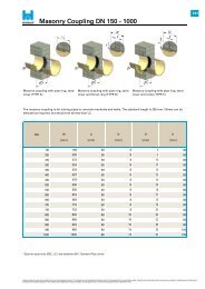
Masonry Coupling DN 150 - 1000<br />
Masonry coupling with pipe ring, sand<br />
cover (TYPE A)<br />
Masonry coupling with pipe ring, sand<br />
cover and thrust ring (TYPE B)<br />
a b<br />
d<br />
h<br />
[mm] [mm]<br />
[mm]<br />
[mm]<br />
150 168<br />
50 8<br />
8<br />
80<br />
200 220<br />
50 8<br />
9<br />
80<br />
250 272<br />
50 8<br />
10<br />
80<br />
300 324<br />
50 8<br />
11<br />
80<br />
350 376<br />
50 8<br />
12<br />
80<br />
400 427<br />
50 8<br />
13<br />
80<br />
450 478<br />
50 8<br />
14<br />
80<br />
500 530<br />
50 8<br />
15<br />
80<br />
550 550<br />
50 8<br />
16<br />
80<br />
600 616<br />
50 8<br />
17<br />
80<br />
650 650<br />
50 8<br />
19<br />
80<br />
700 718<br />
50 8<br />
19<br />
80<br />
750 752<br />
50 8<br />
21<br />
80<br />
800 820<br />
80 10<br />
22<br />
80<br />
860 860<br />
80 10<br />
23<br />
80<br />
900 924<br />
80 10<br />
25<br />
80<br />
960 960<br />
80 10<br />
25<br />
100<br />
1000 1026<br />
80 12<br />
27<br />
100<br />
*<strong>Data</strong> for pipe joints (DEC, LC), see datasheet B01 "Standard <strong>Pipe</strong> Joints"<br />
Masonry coupling with pipe ring, sand<br />
cover and collar (TYPE C)<br />
The masonry coupling is for joining pipes to concrete manholes and walls. The standard length is 300 mm. Others can be<br />
selected as required, but should not be less than LC.<br />
DN<br />
de<br />
[mm]<br />
All figures quoted are values and may slightly vary due to manufacturing tolerances. The information and recommendations reflect the state of our knowledge at the time of publication/update. Therefore the provided data cannot be construed as an express or implied warranty. All details must<br />
be checked and if necessary agreed to in each individual case. HOBAS cannot accept any liability. This also applies to errors, omissions and changes to technical data without notice.<br />
E01<br />
ACCESSORIES
DN<br />
Masonry Coupling DN 1100 - 3600<br />
Masonry coupling with pipe ring, sand<br />
cover (TYPE A)<br />
Masonry coupling with pipe ring, sand<br />
cover and thrust ring (TYPE B)<br />
b d<br />
h<br />
[mm] [mm]<br />
[mm]<br />
1100 1099<br />
80<br />
12 29<br />
100<br />
1200 1229<br />
80<br />
12 30<br />
100<br />
1280 1280<br />
80<br />
12 32<br />
100<br />
1300 1350<br />
80<br />
12 34<br />
100<br />
1400 1434<br />
100<br />
15 35<br />
100<br />
1500 1499<br />
100<br />
15 38<br />
100<br />
1535 1535<br />
100<br />
15 38<br />
100<br />
1600 1638<br />
120<br />
15 39<br />
100<br />
1700 1720<br />
120<br />
20 42<br />
100<br />
1800 1842<br />
120<br />
20 45<br />
120<br />
1900 1940<br />
120<br />
20 46<br />
120<br />
2000 2047<br />
120<br />
20 49<br />
120<br />
2100 2160<br />
120<br />
20 49<br />
120<br />
2200 2250<br />
120<br />
20 50<br />
120<br />
2400 2400<br />
120<br />
20 55<br />
120<br />
2400 2454<br />
120<br />
20 55<br />
120<br />
2500 2555<br />
120<br />
20 67<br />
150<br />
3000 3000<br />
150<br />
20 67<br />
150<br />
3600 3600<br />
150<br />
20 67<br />
150<br />
*<strong>Data</strong> for pipe joints (DEC, LC), see datasheet B01 "Standard <strong>Pipe</strong> Joints"<br />
a<br />
[mm]<br />
Masonry coupling with pipe ring, sand<br />
cover and collar (TYPE C)<br />
The masonry coupling is for joining pipes to concrete manholes and walls. The standard length is 300 mm. Others can be<br />
selected as required, but should not be less than LC.<br />
de<br />
[mm]<br />
All figures quoted are values and may slightly vary due to manufacturing tolerances. The information and recommendations reflect the state of our knowledge at the time of publication/update. Therefore the provided data cannot be construed as an express or implied warranty. All details must<br />
be checked and if necessary agreed to in each individual case. HOBAS cannot accept any liability. This also applies to errors, omissions and changes to technical data without notice.<br />
E01<br />
ACCESSORIES
Manhole Liner<br />
Manhole liners are made of PP, PS (up to around DN 300) or GRP (around DN 400 or larger). They have a water barrier on<br />
the outside or quartz sand coating, depending on the manufacturer.<br />
DN<br />
allowable<br />
deflection*<br />
de ØA E<br />
[mm] [mm] [mm]<br />
150 168 3° 150 70<br />
200 220 3° 207 70<br />
250 272 3° 256 70<br />
300 324 3° 306 70<br />
350 376 3° 355 70<br />
400 427 3° 404 70<br />
500 530 3° 502 70<br />
600 616 2° 585 70<br />
700 718 2° 683 70<br />
800 820 2° 780 70<br />
900 924 2° 878 70<br />
1000 1026 1° 975 70<br />
1200 1229 1° 1170 70 40<br />
*<strong>Data</strong> for pipe joints (DEC, LC), see datasheet B01 "Standard <strong>Pipe</strong> Joints"<br />
All figures quoted are values and may slightly vary due to manufacturing tolerances. The information and recommendations reflect the state of our knowledge at the time of publication/update. Therefore the provided data cannot be construed as an express or implied warranty. All details must<br />
be checked and if necessary agreed to in each individual case. HOBAS cannot accept any liability. This also applies to errors, omissions and changes to technical data without notice.<br />
F<br />
[mm]<br />
40<br />
40<br />
40<br />
40<br />
40<br />
40<br />
40<br />
40<br />
40<br />
40<br />
40<br />
40<br />
G<br />
[mm]<br />
55<br />
55<br />
55<br />
55<br />
55<br />
55<br />
55<br />
55<br />
55<br />
55<br />
55<br />
55<br />
55<br />
E02<br />
ACCESSORIES
DN<br />
Structural Adapters DN 150 - 1000<br />
Structural adapter, sand covered<br />
(TYPE E)<br />
Structural adapter, sand covered<br />
with thrust ring (TYPE F)<br />
Structural adapter, sand covered<br />
with collar (TYPE G)<br />
It consists of a modified pipe with sanding, on request also with a thrust ring or masonry collar. The standard length<br />
is 0.5 or 1 m up to DN 1100 and 0.5 or 1.5 m for DN 1200 according to national standards. Other lengths available on<br />
request.<br />
de a b d h L<br />
[mm] [mm] [mm] [mm] [mm] [mm]<br />
150 168 50 8 8 80 500 / 1000<br />
200 220 50 8 9 80 500 / 1000<br />
250 272 50 8 10 80 500 / 1000<br />
300 324 50 8 11 80 500 / 1000<br />
350 376 50 8 12 80 500 / 1000<br />
400 427 50 8 13 80 500 / 1000<br />
450 478 50 8 14 80 500 / 1000<br />
500 530 50 8 15 80 500 / 1000<br />
550 550 50 8 16 80 500 / 1000<br />
600 616 50 8 17 80 500 / 1000<br />
650 650 50 8 19 80 500 / 1000<br />
700 718 50 8 19 80 500 / 1000<br />
750 752 50 8 21 80 500 / 1000<br />
800 820 80 10 22 80 500 / 1000<br />
860 860 80 10 23 80 500 / 1000<br />
900 924 80 10 25 80 500 / 1000<br />
960 960 80 10 25 100 500 / 1000<br />
1000 1026 80 12 27 100 500 / 1000<br />
All figures quoted are values and may slightly vary due to manufacturing tolerances. The information and recommendations reflect the state of our knowledge at the time of publication/update. Therefore the provided data cannot be construed as an express or implied warranty. All details must<br />
be checked and if necessary agreed to in each individual case. HOBAS cannot accept any liability. This also applies to errors, omissions and changes to technical data without notice.<br />
E03<br />
ACCESSORIES
DN<br />
Structural Adapters DN 1100 - 3600<br />
Structural adapter, sand covered<br />
(TYPE E)<br />
Structural adapter, sand covered with<br />
thrust ring (TYPE F)<br />
Structural adapter, sand covered with<br />
collar (TYPE G)<br />
It consists of a modified pipe with sanding, on request also with a thrust ring or masonry collar. The standard length<br />
is 0.5 or 1 m up to DN 1100 and 0.5 or 1.5 m for DN 1200 according to national standards. Other lengths available on<br />
request.<br />
de a b d h L<br />
[mm] [mm] [mm] [mm] [mm] [mm]<br />
1100 1099 80 12 29 100 500/ 1500<br />
1200 1229 80 12 30 100 500/ 1500<br />
1280 1280 80 12 32 100 500/ 1500<br />
1350 1350 80 12 34 100 500/ 1500<br />
1400 1434 100 15 35 100 500/ 1500<br />
1500 1499 100 15 38 100 500/ 1500<br />
1535 1535 100 15 38 100 500/ 1500<br />
1600 1638 120 15 39 100 500/ 1500<br />
1700 1720 120 20 42 100 500/ 1500<br />
1800 1842 120 20 45 120 500/ 1500<br />
1900 1940 120 20 46 120 500/ 1500<br />
2000 2047 120 20 49 120 500/ 1500<br />
2100 2160 120 20 49 120 500/ 1500<br />
2200 2250 120 20 50 120 500/ 1500<br />
2400 2400 120 20 55 120 500/ 1500<br />
2400 2454 120 20 55 120 500/ 1500<br />
2500 2555 120 20 67 150 500/ 1500<br />
3000 3000 150 20 67 150 500/ 1500<br />
3600 3600 150 20 67 150 500/ 1500<br />
All figures quoted are values and may slightly vary due to manufacturing tolerances. The information and recommendations reflect the state of our knowledge at the time of publication/update. Therefore the provided data cannot be construed as an express or implied warranty. All details must<br />
be checked and if necessary agreed to in each individual case. HOBAS cannot accept any liability. This also applies to errors, omissions and changes to technical data without notice.<br />
E03<br />
ACCESSORIES
Properties/long-term values:<br />
Density<br />
Tensile elastic modulus (at 23°C)<br />
Tensile strength (standard)<br />
Tensile strength (locked design)<br />
Tensile strain (at break): < <strong>PN</strong> 10<br />
Tensile strain (at break): ≥ <strong>PN</strong> 10<br />
Poisson's ratio<br />
Compressive elastic modulus (at 23°C)<br />
Compressive strength<br />
Compressive strain (at break)<br />
Flexural modulus<br />
Flexural strength<br />
Flexural strain (at break)<br />
Circumferential strain at <strong>PN</strong><br />
Circumferential strain at 1.5 x <strong>PN</strong><br />
Temperature resistance<br />
Chemical resistance (pH range)<br />
Temperature expansion coefficient<br />
Thermal conductivity<br />
Heat capacity<br />
Material <strong>Data</strong><br />
The laminate structure of HOBAS GRP <strong>Pipe</strong>s may vary, depending on the requirements such as pressure class (<strong>PN</strong>), stiffness<br />
(SN) or longitudinal tensile strength. The material data in the table should therefore be considered as a giudeline.<br />
We can provide more accurate material data for specific pipes on request.<br />
The properties of the pipes manufactured, such as stiffness, ring deflection and longitudinal tensile strength are routinely<br />
checked as part of quality assurance. Geometric properties, such as wall thickness, outside diameter and liner thickness, are<br />
measured and checked to internal quality standards.<br />
Test procedures and regulations are defined in the applicable standards. You will find more detailed information about them<br />
and other material tests, such as abrasion, long-term values, hydraulic properties, chemical resistance, etc. in our brochure<br />
CC-GRP <strong>Pipe</strong>s Features, Tests and Benefits.<br />
Characteristic properties for HOBAS GRP <strong>Pipe</strong>s:<br />
Pressure wave propagation rate<br />
Roughness (to Colebrook White) k<br />
*Temperature up to 80°C on request<br />
**Higher/lower pH on request<br />
Material data Unit<br />
kg/m³<br />
MPa<br />
MPa<br />
MPa<br />
%<br />
%<br />
-<br />
MPa<br />
MPa<br />
%<br />
MPa<br />
MPa<br />
%<br />
%<br />
%<br />
°C<br />
pH<br />
1/K<br />
W/m/K<br />
kJ/kg/K<br />
m/s<br />
mm<br />
Orientation<br />
Circumferential Longitudinal<br />
90 - 130 15 - 40<br />
12000 - 18000 12000 - 18000<br />
130 - 140<br />
~ 2000<br />
10000 - 15000 10000 - 12000<br />
1.2 - 1.5<br />
0.25<br />
1.8 - 2.0 1.0 - 1.4<br />
~ 0.3 ~ 0.25<br />
1.2 - 1.5<br />
200 80 - 100<br />
90 - 100<br />
1.8 - 2.0<br />
10000 - 15000 -<br />
120 - 140 15 - 40<br />
1.6 - 2.2 1.0<br />
0.2 - 0.3 -<br />
0.3 - 0.4 -<br />
≤ 40 *<br />
1 - 10 **<br />
26 - 30 x 10-6<br />
0.5 - 1.0<br />
1.0 - 1.4<br />
~ 450<br />
0.01 - 0.016<br />
All figures quoted are values and may slightly vary due to manufacturing tolerances. The information and recommendations reflect the state of our knowledge at the time of publication/update. Therefore the provided data cannot be construed as an express or implied warranty. All details must<br />
be checked and if necessary agreed to in each individual case. HOBAS cannot accept any liability. This also applies to errors, omissions and changes to technical data without notice.<br />
F01<br />
MATERIAL DATA
HOBAS Engineering Austria<br />
Pischeldorfer Strasse 128<br />
9020 Klagenfurt<br />
Austria<br />
T +43.463.48 24 24<br />
F +43.463.48 21 21<br />
info@hobas.com<br />
www.hobas.com<br />
HOBAS Group Worldwide<br />
HOBAS manufactures and markets HOBAS GRP <strong>Pipe</strong><br />
<strong>Systems</strong>. The HOBAS Network includes HOBAS Pro-<br />
duction Facilities and Sales Organizations in Europe and<br />
throughout the world.<br />
We develop and manufacture HOBAS <strong>Product</strong>s con-<br />
serving nature‘s resources and with respect for our<br />
environment. Visit our website to find out more about<br />
the HOBAS Environmental Policy.