h Technical Product Data FW Pressure Pipe Systems - Hobas
h Technical Product Data FW Pressure Pipe Systems - Hobas
h Technical Product Data FW Pressure Pipe Systems - Hobas

Create successful ePaper yourself
Turn your PDF publications into a flip-book with our unique Google optimized e-Paper software.
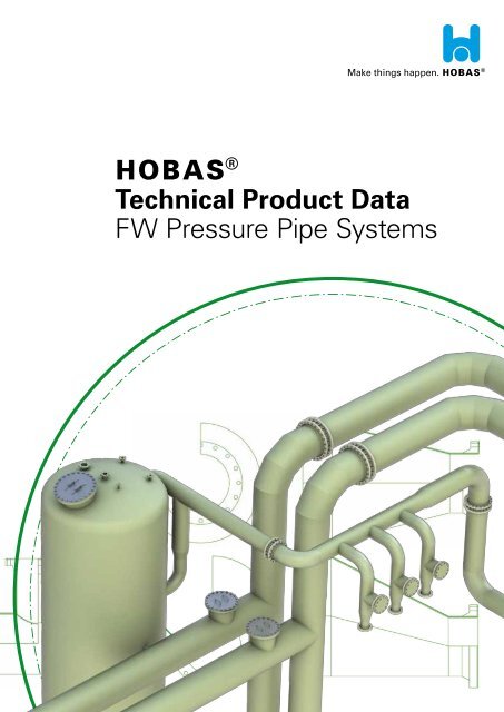
h<br />
<strong>Technical</strong> <strong>Product</strong> <strong>Data</strong><br />
<strong>FW</strong> <strong>Pressure</strong> <strong>Pipe</strong> <strong>Systems</strong>
© E Engineering GmbH<br />
All rights reserved.<br />
Publication: 10/2012<br />
All rights reserved. No part of this document may be reproduced or utilized in any form or by any means without our prior written permission.<br />
All information in the document is correct at the time of going to press. However, we reserve the right to make changes without<br />
notice, in particular to technical data. The data given is not binding and must therefore be checked in each individual case and revised as<br />
appropriate.
Fields of application:<br />
� �<br />
� Metal Industry<br />
�<br />
� Power Industry<br />
�<br />
� Textile, Paper and Pulp Industry<br />
�<br />
� Mining Industry<br />
Standard product range<br />
Nominal Diameter [DN]<br />
Nominal <strong>Pressure</strong> [PN]<br />
Temperature range up to 160° C (higher temperatures on request)<br />
<strong>Pipe</strong> systems<br />
Process equipment according to PED<br />
(Process Equipment Directive)<br />
Thermoplastic Liner<br />
HOBAS <strong>FW</strong> <strong>Pressure</strong> <strong>Pipe</strong> <strong>Systems</strong><br />
HOBAS supplies various kinds of industries where a large variety of operating conditions call for chemically, mechanically and<br />
thermally resistant pipelines, vessels and process equipment. HOBAS Industrial <strong>Product</strong>s are made from GRP (Glass Fiber<br />
Reinforced Plastic) which can be optionally equipped with a thermoplastic liner. According to specifications and customer<br />
requirements, products are manufactured by filament winding or hand lamination.<br />
Chemical Industry Semiconductor Industry<br />
25 - 4000<br />
1 - 40<br />
- <strong>Pipe</strong>s, Joints, Fittings (DIN 16965/66: <strong>Pipe</strong> Type D, E, N, B)<br />
- Vessels for acids and bases<br />
- Bio Reactors<br />
- Chlorine Drying Towers<br />
- Cyclones<br />
- Ducting<br />
- Electro Filters<br />
- Scrubbers<br />
- Double Chamber Storage Tanks for chemicals<br />
- Customized Shapes and Configurations<br />
- PVC - Polyvinyl chloride (chlorinated PVC-C, unplasticized PVC-U)<br />
- PE-HD - High Density Polyethylen PVC-C - Chlorinated polyvinyl chloride<br />
- PP - Polypropylene<br />
- PVDF - Polyvinylidene fluoride<br />
- ECTFE - Ethylene chlorotrifluoroethylene<br />
- FEP - Fluorinated ethylene propylene<br />
- PFA - Perfluoroalkoxy<br />
Sea Water Desalination<br />
Plastics Industry<br />
Air Treatment<br />
3
Abbreviations:<br />
b Flange sheet, loose flange<br />
D Outer flange diameter<br />
di Inner pipe diameter<br />
DIN German Institute for Standardization<br />
DN Nominal Diameter<br />
s4 <strong>Pipe</strong> wall thickness (<strong>Pipe</strong> Type B without thermoplastic liner)<br />
s3 Structure laminate<br />
s2 Chemical protection layer<br />
s1 Thickness of thermoplastic liner (for <strong>Pipe</strong> Type B)<br />
<strong>FW</strong> Filament Winding<br />
k Bolt circle diameter<br />
L Length<br />
PN Nominal <strong>Pressure</strong><br />
R Radius<br />
GRP Glass fiber plastic (glass fiber reinforced unsaturated polyester resin)<br />
4
PIPES<br />
PIPE JOINTS<br />
FITTINGS<br />
PROCESS<br />
EQUIPMENT<br />
ACCESSORIES<br />
A40<br />
A41<br />
A42<br />
A43<br />
A44<br />
A44<br />
B41<br />
B42<br />
C41<br />
C42<br />
C43<br />
C43<br />
C44<br />
C44<br />
C45<br />
C45<br />
D41<br />
D42<br />
D43<br />
D44<br />
D45<br />
E41<br />
E42<br />
E43<br />
F41<br />
Overview <strong>Pipe</strong>s and Wall Structure<br />
<strong>Pipe</strong>s and Fittings<br />
<strong>Pipe</strong> Type D<br />
<strong>Pipe</strong> Type E<br />
<strong>Pipe</strong> Type N<br />
<strong>Pipe</strong> Type B<br />
Laminated Joint <strong>Pipe</strong> Type D / E / N<br />
Laminated and Welded Joint <strong>Pipe</strong> Type B<br />
Radiused Bends D / E / N / B<br />
Miter Bends D / E / N / B<br />
T-piece D / E / N / B DN 25-250<br />
T-piece D / E / N / B DN 300-1000<br />
Reducers D / E / N / B DN 25-250<br />
Reducers D / E / N / B DN 300-1000<br />
Fixed Flange D / E / N / B<br />
Stub Flange D / E / N / B<br />
Storage Tank<br />
Absorber<br />
Cyclone<br />
GRP Header<br />
<strong>Pipe</strong> Spool Manufacture<br />
SMC Flange Ring<br />
SMC Stub Flange<br />
SMC Blind Flange<br />
Material Specifications<br />
5
Overview <strong>Pipe</strong>s and Wall Structure<br />
<strong>Pipe</strong> Type D<br />
in compliance with<br />
DIN 16965, part 4<br />
<strong>Pipe</strong> Type E<br />
in compliance with<br />
DIN 16965, part 5<br />
<strong>Pipe</strong> Type N<br />
in compliance with<br />
DIN 16965<br />
<strong>Pipe</strong> Type B<br />
in compliance with<br />
DIN 16965, part 2<br />
Chemical protection layer<br />
Glass<br />
contents:<br />
Glass<br />
contents:<br />
Glass<br />
contents:<br />
s2<br />
� 2,5mm<br />
� 25%<br />
Resin-rich with C-glass<br />
fleece or synthetic fleece<br />
� 25%<br />
� 25%<br />
Glass<br />
contents:<br />
Glass<br />
contents:<br />
Glass<br />
contents:<br />
Glass<br />
contents:<br />
Structure laminate Outer surface<br />
� 55%<br />
� 30%<br />
� 40%<br />
� 55%<br />
Glass<br />
contents:<br />
Chemical protection layer Structure laminate Outer surface<br />
s3<br />
dependent on pressure class<br />
Glass fiber stands, -mats and<br />
-fabric<br />
s2 s3<br />
� 0,4mm<br />
Resin-rich with C-glass<br />
fleece or synthetic fleece<br />
dependent on pressure class<br />
Hand lay-up laminate with<br />
textile glass mats<br />
Glass<br />
contents:<br />
Glass<br />
contents:<br />
Glass<br />
contents:<br />
0%<br />
Resin-rich with C-glass<br />
fleece or synthetic fleece<br />
� 0,2mm<br />
0%<br />
Resin-rich with C-glass<br />
fleece or synthetic fleece<br />
Chemical protection layer Structure laminate Outer surface<br />
s2 s3<br />
� 2,5 mm<br />
Resin-rich with C-glass<br />
fleece or synthetic fleece<br />
Chemical protection layer Structure laminate Outer surface<br />
s1 s3<br />
Thermoplastic liner<br />
PVC, PVC-C, PVC-U, PE-HD,<br />
PP, PVDF, ECTFE, FEP, PFA<br />
� 3,5 mm<br />
Glass fiber stands, -mats and<br />
-fabric<br />
dependent on pressure class<br />
Glass fiber stands, -mats and<br />
-fabric<br />
� 0,2mm<br />
� 0,2mm<br />
0%<br />
Resin-rich with C-glass<br />
fleece or synthetic fleece<br />
� 0,2mm<br />
0%<br />
Resin-rich with C-glass<br />
fleece or synthetic fleece<br />
All figures quoted are values and may slightly vary due to manufacturing tolerances. The information and recommendations reflect the state of our knowledge at the time of publication/update. Therefore the provided data cannot be construed as an express or<br />
implied warranty. All details must be checked and if necessary agreed to in each individual case. HOBAS cannot accept any liability. This also applies to errors, omissions and changes to technical data without notice.<br />
6<br />
A40
<strong>Pipe</strong>s and Fittings<br />
<strong>Pipe</strong>s and Fittings <strong>Pipe</strong> Type D, E, N<br />
<strong>Pipe</strong>s and Fittings <strong>Pipe</strong> Type B with thermoplastic liner<br />
<strong>Pipe</strong>s and Fittings with laminated<br />
ends<br />
<strong>Pipe</strong>s and Fittings with one<br />
laminated end and one flange<br />
joint (fixed or loose flange)<br />
<strong>Pipe</strong>s and Fittings with flange<br />
joints (fixed or loose flange)<br />
<strong>Pipe</strong>s and Fittings with laminated /<br />
welded ends<br />
<strong>Pipe</strong>s and Fittings with one<br />
laminated end and one flange<br />
joint (fixed or loose flange)<br />
<strong>Pipe</strong>s and Fittings with flange<br />
joints (fixed or loose flange)<br />
All figures quoted are values and may slightly vary due to manufacturing tolerances. The information and recommendations reflect the state of our knowledge at the time of publication/update. Therefore the provided data cannot be construed as an express or<br />
implied warranty. All details must be checked and if necessary agreed to in each individual case. HOBAS cannot accept any liability. This also applies to errors, omissions and changes to technical data without notice.<br />
7<br />
A41
<strong>Pipe</strong> Type D<br />
<strong>Pipe</strong> Type D is produced to DIN 16965 part 4 on the basis of UP and vinylester resins. <strong>Pipe</strong>s of this same type can be<br />
joined by laminates (see <strong>Pipe</strong> Joints) or flanges (see Fittings).<br />
DN<br />
25<br />
32<br />
40<br />
50<br />
65<br />
80<br />
100<br />
125<br />
150<br />
200<br />
250<br />
300<br />
350<br />
400<br />
500<br />
600<br />
700<br />
800<br />
900<br />
1000<br />
1100 - 4000<br />
> PN 16 on request<br />
* Tolerances in accordance with DIN 16965, part 4<br />
** Standard pipe length, other lengths available<br />
PN 16<br />
di *<br />
L **<br />
s4 min *<br />
s4 min<br />
[mm] [m] [mm]<br />
*<br />
[mm]<br />
25 5 4,4<br />
4,4<br />
32 6 4,4<br />
4,4<br />
40 6 4,4<br />
4,4<br />
50 6 4,4<br />
4,4<br />
65 6 4,4<br />
4,4<br />
80 6 4,4<br />
4,4<br />
100 6 4,4<br />
4,4<br />
125 6 4,4<br />
4,4<br />
150 6 4,4<br />
4,6<br />
200 6 4,4<br />
5,3<br />
250 6 4,7<br />
6,0<br />
300 6 5,1<br />
6,6<br />
350 6 5,5<br />
7,3<br />
400 6 5,9<br />
8,0<br />
500 6 6,8<br />
9,3<br />
600 6 7,6<br />
10,7<br />
700 6 8,4<br />
12,0<br />
800 6 9,3<br />
13,4<br />
900 6 10,1<br />
14,8<br />
1000 6 11,0<br />
16,1<br />
On request<br />
All figures quoted are values and may slightly vary due to manufacturing tolerances. The information and recommendations reflect the state of our knowledge at the time of publication/update. Therefore the provided data cannot be construed as an express or<br />
implied warranty. All details must be checked and if necessary agreed to in each individual case. HOBAS cannot accept any liability. This also applies to errors, omissions and changes to technical data without notice.<br />
PN 10<br />
A42<br />
8
PN 16 on request<br />
<strong>Pipe</strong> Type E<br />
<strong>Pipe</strong> Type E is produced and reinforced with glass fiber to DIN 16965 part 5 on the basis of UP and vinylester resins. <strong>Pipe</strong>s of<br />
this same type can be joined by laminates (see <strong>Pipe</strong> Joints) or flanges (see Fittings).<br />
DN<br />
25<br />
32<br />
40<br />
50<br />
65<br />
80<br />
100<br />
125<br />
150<br />
200<br />
250<br />
300<br />
350<br />
400<br />
500<br />
600<br />
700<br />
800<br />
900<br />
1000<br />
* Tolerances in accordance with DIN 16965, part 5<br />
** Standard pipe length, other lengths available<br />
PN 6 PN 10 PN 16<br />
di *<br />
L **<br />
s4 min *<br />
s4 min *<br />
s4 min *<br />
[mm] [m] [mm] [mm] [mm]<br />
25 5 5,0 5,0 5,0<br />
32 6 5,0 5,0 5,0<br />
40 6 5,0 5,0 5,0<br />
50 6 5,0 5,0 5,0<br />
65 6 5,0 5,0 5,1<br />
80 6 5,0 5,0 6,1<br />
100 6 5,0 5,0 7,3<br />
125 6 5,0 5,9 8,9<br />
150 6 5,0 6,8 10,5<br />
200 6 5,6 8,7 13,6<br />
250 6 6,7 10,7 16,8<br />
300 6 7,9 12,6 19,9<br />
350 6 9,0 14,5 23,1<br />
400 6 10,1 16,4 26,2<br />
500 6 12,4 20,3 32,5<br />
600 6 14,7 24,1 38,8<br />
700 6 17,0 27,9 45,1<br />
800 6 19,2 31,8 51,4<br />
900 6 21,5 35,6 57,7<br />
1000 6 23,8 39,5 64,0<br />
1100 - 4000 On request<br />
All figures quoted are values and may slightly vary due to manufacturing tolerances. The information and recommendations reflect the state of our knowledge at the time of publication/update. Therefore the provided data cannot be construed as an express or<br />
implied warranty. All details must be checked and if necessary agreed to in each individual case. HOBAS cannot accept any liability. This also applies to errors, omissions and changes to technical data without notice.<br />
9<br />
A43
500<br />
600<br />
700<br />
800<br />
900<br />
1000<br />
1100 - 4000<br />
> PN 16 on request<br />
<strong>Pipe</strong> Type N<br />
<strong>Pipe</strong> Type N is produced on the basis of UP and vinylester resins. <strong>Pipe</strong>s of this same type can be joined by laminates<br />
(see <strong>Pipe</strong> Joints) or flanges (see Fittings).<br />
DN<br />
25<br />
32<br />
40<br />
50<br />
65<br />
80<br />
100<br />
125<br />
150<br />
200<br />
250<br />
300<br />
350<br />
400<br />
* plus tolerances<br />
** Standard pipe length, other lengths available<br />
PN 10 PN 16<br />
di *<br />
L **<br />
s4 min *<br />
s4 min *<br />
[mm] [m] [mm] [mm]<br />
25 6 5,0 5,0<br />
32 6 5,0 5,0<br />
40 6 5,0 5,0<br />
50 6 5,0 5,0<br />
65 6 5,0 5,0<br />
80 6 5,0 5,1<br />
100 6 5,0 5,7<br />
125 6 5,0 6,4<br />
150 6 5,4 7,2<br />
200 6 6,3 8,7<br />
250 6 7,2 10,2<br />
300 6 8,1 11,7<br />
350 6 9,0 13,2<br />
400 6 10,0 14,7<br />
500 6 11,8 17,7<br />
600 6 13,6<br />
700 6 15,4<br />
800 6 17,3<br />
900 6 19,1<br />
1000 6 20,9<br />
On request<br />
All figures quoted are values and may slightly vary due to manufacturing tolerances. The information and recommendations reflect the state of our knowledge at the time of publication/update. Therefore the provided data cannot be construed as an express or<br />
implied warranty. All details must be checked and if necessary agreed to in each individual case. HOBAS cannot accept any liability. This also applies to errors, omissions and changes to technical data without notice.<br />
10<br />
A44
DN<br />
25<br />
32<br />
40<br />
50<br />
65<br />
125<br />
<strong>Pipe</strong> Type B<br />
* di dependent on the thermoplastic liner<br />
<strong>Pipe</strong> Type B is glass fiber reinforced with thermoplastic liner and produced to DIN 16965 part 2 on the basis of UP and<br />
vinylester resins. <strong>Pipe</strong>s of this type can be joined with either welded or laminated joints (see <strong>Pipe</strong> Joints) or flanges (see<br />
Fittings).<br />
The resistance against aggressive media depends on the thermoplastic liner. PVC, PVC-C, PVC-U, PE-HD, PP, PVDF, ECTFE,<br />
FEP and PFA are processed as standard according to customer requirements.<br />
80<br />
100<br />
150<br />
200<br />
250<br />
300<br />
350<br />
400<br />
500<br />
600<br />
700<br />
800<br />
900<br />
1000<br />
1100 - 4000<br />
> PN 16 on request<br />
* Tolerances in accordance with DIN 16965, part 2<br />
** Standard pipe length, other lengths available<br />
PN 6 PN 10 PN 16<br />
L **<br />
s4 min *<br />
s4 min *<br />
s4 min *<br />
[m] [mm] [mm] [mm]<br />
5-6 2,9 2,9 2,9<br />
5-6 2,9 2,9 2,9<br />
5-6 2,9 2,9 2,9<br />
5-6 2,9 2,9 2,9<br />
5-6,2 2,9 2,9 2,9<br />
5-6,2 2,9 2,9 2,9<br />
5-6,2 2,9 2,9 2,9<br />
5-6,2 2,9 2,9 2,9<br />
5-6,2 2,9 2,9 3,2<br />
5-6,2 2,9 2,9 3,7<br />
5-6,2 2,9 3,1 4,4<br />
5-6,2 2,9 3,7 5,3<br />
5-6,2 2,9 4,0 5,8<br />
5-6,2 3,1 4,4 6,4<br />
5-6,2 3,6 5,2 7,8<br />
5-6,2 4,1 6,1 9,1<br />
5-6,2 4,6 7,0 10,6<br />
5-6,2 5,1 7,7 11,8<br />
5-6,2 5,6 8,6 13,2<br />
5-6,2 6,1 9,4 14,5<br />
On request<br />
All figures quoted are values and may slightly vary due to manufacturing tolerances. The information and recommendations reflect the state of our knowledge at the time of publication/update. Therefore the provided data cannot be construed as an express or<br />
implied warranty. All details must be checked and if necessary agreed to in each individual case. HOBAS cannot accept any liability. This also applies to errors, omissions and changes to technical data without notice.<br />
11<br />
A45
DN<br />
65<br />
80<br />
100<br />
125<br />
150<br />
200<br />
250<br />
300<br />
350<br />
400<br />
500<br />
600<br />
700<br />
800<br />
900<br />
1000<br />
1100-4000<br />
Tolerances:<br />
> PN 16 on request<br />
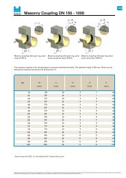
Laminated Joint <strong>Pipe</strong> Type D / E / N<br />
Joints are laminated to permanently connect pipes and fittings type D, E and N to DIN 16966, part 8.<br />
25<br />
32<br />
40<br />
50<br />
s5 min<br />
[mm]<br />
4,0<br />
4,0<br />
4,0<br />
4,0<br />
4,0<br />
4,0<br />
4,0<br />
5,0<br />
6,0<br />
4,5<br />
6,0<br />
7,0<br />
8,0<br />
9,0<br />
11,5<br />
14,0<br />
16,0<br />
18,5<br />
20,5<br />
23,0<br />
PN 6<br />
PN 10<br />
L1 min s5 min L1 min s5 min L1 min<br />
[mm] [mm] [mm] [mm] [mm]<br />
110 4,0 110 4,0 110<br />
110 4,0 110 4,0 110<br />
110 4,0 110 4,0 110<br />
110 4,0 110 4,0 110<br />
110 4,0 110 4,5 110<br />
110 4,0 110 5,0 120<br />
110 4,0 110 6,5 140<br />
110 5,0 110 8,0 175<br />
110 6,0 130 9,5 210<br />
110 8,0 165 13,0 280<br />
125 10,0 205 16,0 345<br />
150 11,5 250 19,0 415<br />
170 13,5 290 22,0 460<br />
200 15,5 330 25,0 550<br />
240 19,5 410 31,5 685<br />
290 23,0 480 38,0 745<br />
335 27,0 560 44,0 880<br />
390 31,0 640 50,0 990<br />
430 35,0 720 57,0 1115<br />
480 39,0 795 63,0 1235<br />
On request<br />
All figures quoted are values and may slightly vary due to manufacturing tolerances. The information and recommendations reflect the state of our knowledge at the time of publication/update. Therefore the provided data cannot be construed as an express or<br />
implied warranty. All details must be checked and if necessary agreed to in each individual case. HOBAS cannot accept any liability. This also applies to errors, omissions and changes to technical data without notice.<br />
PN 16<br />
B41<br />
12
t2 = 10-20mm<br />
> PN 16 on request<br />
Laminated and Welded Joint <strong>Pipe</strong> Type B<br />
Joints are welded and laminated to permanently connect type B pipes and fittings with thermoplastic liner to DIN 16966,<br />
part 8.<br />
DN<br />
25<br />
32<br />
40<br />
50<br />
65<br />
80<br />
100<br />
125<br />
150<br />
200<br />
250<br />
300<br />
350<br />
400<br />
500<br />
600<br />
700<br />
800<br />
900<br />
1000<br />
s5 min<br />
[mm]<br />
4,0<br />
4,0<br />
4,0<br />
4,0<br />
4,0<br />
4,0<br />
4,0<br />
4,0<br />
4,0<br />
4,0<br />
4,0<br />
5,0<br />
5,5<br />
6,5<br />
8,0<br />
9,5<br />
11,0<br />
12,5<br />
14,0<br />
15,5<br />
PN 6<br />
PN 10 PN 16<br />
L1 s5 min L1 s5 min L1<br />
[mm] [mm] [mm] [mm] [mm]<br />
110 4,0 110 4,0 110<br />
110 4,0 110 4,0 110<br />
110 4,0 110 4,0 110<br />
110 4,0 110 4,0 110<br />
110 4,0 110 4,0 110<br />
110 4,0 110 4,0 120<br />
110 4,0 110 4,5 140<br />
110 4,0 110 5,5 175<br />
110 4,0 130 6,5 210<br />
110 5,5 165 8,5 280<br />
125 6,5 205 10,5 345<br />
150 8,0 250 12,5 415<br />
170 9,0 290 15,0 460<br />
200 10,5 330 17,0 550<br />
240 13,0 410 21,0 685<br />
290 15,5 480 25,0 745<br />
335 18,0 560 29,5 880<br />
390 20,5 640 33,5 990<br />
430 23,0 720 37,5 1115<br />
480 26,0 795 42,0 1235<br />
1100 - 4000 On request<br />
All figures quoted are values and may slightly vary due to manufacturing tolerances. The information and recommendations reflect the state of our knowledge at the time of publication/update. Therefore the provided data cannot be construed as an express or<br />
implied warranty. All details must be checked and if necessary agreed to in each individual case. HOBAS cannot accept any liability. This also applies to errors, omissions and changes to technical data without notice.<br />
13<br />
B42
Radiused Bends D / E / N / B<br />
Radiused bends are glass fiber reinforced and produced to DIN 16966 part 2 on the basis of UP and vinylester resins. Bends<br />
are available with 45° and 90° angles as standard, other angles are available on request. <strong>Pipe</strong>s of this type can be connected<br />
with laminated joints (see <strong>Pipe</strong> Joints) or flanges (see Fittings).<br />
DN<br />
25<br />
32<br />
40<br />
50<br />
65<br />
80<br />
100<br />
125<br />
150<br />
200<br />
250<br />
300<br />
350<br />
400<br />
500<br />
600<br />
700<br />
800<br />
Radiused Bend 90°<br />
R<br />
[m]<br />
72<br />
88<br />
104<br />
71<br />
84<br />
105<br />
138<br />
157<br />
195<br />
283<br />
362<br />
405<br />
463<br />
532<br />
654<br />
693<br />
850<br />
1000<br />
Radiused Bend 45°<br />
90° 45°<br />
L L<br />
[mm] [mm]<br />
110 70<br />
130 80<br />
150 90<br />
180 105<br />
140 85<br />
165 100<br />
205 115<br />
245 135<br />
285 150<br />
365 190<br />
450 225<br />
525 260<br />
600 290<br />
680 325<br />
830 390<br />
950 430<br />
1100 490<br />
1250 545<br />
<strong>Pipe</strong> Type B: Dimensions dependent on the thickness of the thermoplastic liner.<br />
* DN 25 - 125: ± 0,5mm | DN 150 - 250: ± 1,0mm | DN 300 - 400: ± 1,5mm | DN 500 - 700: ± 2,0mm | DN 800 - 1000: ± 2,5mm<br />
All figures quoted are values and may slightly vary due to manufacturing tolerances. The information and recommendations reflect the state of our knowledge at the time of publication/update. Therefore the provided data cannot be construed as an express or<br />
implied warranty. All details must be checked and if necessary agreed to in each individual case. HOBAS cannot accept any liability. This also applies to errors, omissions and changes to technical data without notice.<br />
C41<br />
14
Miter Bends D / E / N / B<br />
Miter bends are glass fiber reinforced and produced to DIN 16966 part 2 on the basis of UP and vinylester resins. Bends are<br />
available with 45° and 90° angles as standard, other angles are available on request. <strong>Pipe</strong>s of this type can be connected with<br />
laminated joints (see <strong>Pipe</strong> Joints) or flanges (see Fittings).<br />
DN<br />
150<br />
200<br />
250<br />
300<br />
350<br />
400<br />
500<br />
600<br />
700<br />
800<br />
900<br />
1000<br />
Miter bend 90°<br />
90° 45°<br />
R L R L<br />
[m] [mm] [mm] [mm]<br />
400 550 500 300<br />
400 575 500 400<br />
450 625 550 400<br />
450 650 550 425<br />
525 700 600 425<br />
600 800 600 450<br />
750 950 750 525<br />
900 1075 900 600<br />
1050 1200 1050 650<br />
1200 1350 1200 700<br />
1350 1450 1350 725<br />
1270 1570 1270 750<br />
1100 - 4000 On request<br />
Miter bend 90°<br />
<strong>Pipe</strong> Type B: Dimensions dependent on the thickness of the thermoplastic liner.<br />
* DN 25 - 125: ± 0,5mm | DN 150 - 250: ± 1,0mm | DN 300 - 400: ± 1,5mm | DN 500 - 700: ± 2,0mm | DN 800 - 1000: ± 2,5mm<br />
All figures quoted are values and may slightly vary due to manufacturing tolerances. The information and recommendations reflect the state of our knowledge at the time of publication/update. Therefore the provided data cannot be construed as an express or<br />
implied warranty. All details must be checked and if necessary agreed to in each individual case. HOBAS cannot accept any liability. This also applies to errors, omissions and changes to technical data without notice.<br />
15<br />
C42
T-piece D / E / N / B DN 25-250<br />
T-pieces are glass fiber reinforced and are produced to DIN 16966 part 4 on the basis of UP and vinylester resins. <strong>Pipe</strong>s of<br />
this type can be connected with laminated joints (see <strong>Pipe</strong> Joints) or flanges (see Fittings).<br />
DN 1<br />
25<br />
32<br />
40<br />
50<br />
65<br />
80<br />
100<br />
125<br />
150<br />
200<br />
250<br />
DN 2<br />
0<br />
<strong>Pipe</strong> Type B: Dimensions dependent on the thickness of the thermoplastic liner.<br />
25<br />
25<br />
25<br />
32<br />
25<br />
32<br />
40<br />
32<br />
40<br />
50<br />
40<br />
50<br />
65<br />
50<br />
65<br />
80<br />
65<br />
80<br />
100<br />
80<br />
100<br />
125<br />
100<br />
125<br />
150<br />
125<br />
150<br />
200<br />
All figures quoted are values and may slightly vary due to manufacturing tolerances. The information and recommendations reflect the state of our knowledge at the time of publication/update. Therefore the provided data cannot be construed as an express or<br />
implied warranty. All details must be checked and if necessary agreed to in each individual case. HOBAS cannot accept any liability. This also applies to errors, omissions and changes to technical data without notice.<br />
L1<br />
[mm]<br />
130<br />
130<br />
150<br />
180<br />
140<br />
165<br />
205<br />
245<br />
285<br />
365<br />
450<br />
L2<br />
[mm]<br />
170<br />
170<br />
175<br />
180<br />
190<br />
195<br />
205<br />
270<br />
240<br />
240<br />
290<br />
260<br />
310<br />
310<br />
340<br />
16<br />
C43
T-piece D / E / N / B DN 300-1000<br />
T-pieces are glass fiber reinforced and are produced to DIN 16966 part 4 on the basis of UP and vinylester resins. <strong>Pipe</strong>s of<br />
this type can be connected with laminated joints (see <strong>Pipe</strong> Joints) or flanges (see Fittings).<br />
DN 1<br />
300<br />
350<br />
400<br />
500<br />
600<br />
700<br />
800<br />
900<br />
1000<br />
1100 - 4000<br />
DN 2<br />
800<br />
900<br />
L1<br />
[mm]<br />
525<br />
600<br />
680<br />
830<br />
950<br />
1000<br />
1250<br />
1400<br />
1500<br />
<strong>Pipe</strong> Type B: Dimensions dependent on the thickness of the thermoplastic liner.<br />
150<br />
200<br />
250<br />
200<br />
250<br />
300<br />
250<br />
300<br />
350<br />
300<br />
350<br />
400<br />
350<br />
400<br />
500<br />
400<br />
500<br />
600<br />
500<br />
600<br />
700<br />
600<br />
700<br />
800<br />
700<br />
On request<br />
All figures quoted are values and may slightly vary due to manufacturing tolerances. The information and recommendations reflect the state of our knowledge at the time of publication/update. Therefore the provided data cannot be construed as an express or<br />
implied warranty. All details must be checked and if necessary agreed to in each individual case. HOBAS cannot accept any liability. This also applies to errors, omissions and changes to technical data without notice.<br />
L2<br />
[mm]<br />
360<br />
365<br />
415<br />
395<br />
445<br />
445<br />
470<br />
470<br />
520<br />
525<br />
575<br />
575<br />
620<br />
620<br />
670<br />
675<br />
725<br />
750<br />
775<br />
800<br />
800<br />
850<br />
905<br />
C43<br />
17
200<br />
250<br />
Reducers D / E / N / B DN 25-250<br />
Concentric reducers are glass fiber reinforced and produced to DIN 16966 part 5 on the basis of UP and vinylester resin.<br />
<strong>Pipe</strong>s of this type can be connected with laminated joints (see <strong>Pipe</strong> Joints) or flanges (see Fittings).<br />
DN 1<br />
32<br />
40<br />
50<br />
65<br />
80<br />
100<br />
125<br />
150<br />
DN 2<br />
25<br />
25<br />
32<br />
25<br />
32<br />
40<br />
32<br />
40<br />
50<br />
40<br />
50<br />
65<br />
50<br />
65<br />
80<br />
65<br />
80<br />
100<br />
80<br />
100<br />
125<br />
100<br />
125<br />
150<br />
125<br />
150<br />
200<br />
<strong>Pipe</strong> Type B: Dimensions dependent on the thickness of the thermoplastic liner.<br />
L1 L2 L3 L4<br />
[mm] [mm] [mm] [mm]<br />
180 85 20 20<br />
205 40 40<br />
85<br />
200 20 20<br />
235 65 60<br />
230 85 45 45<br />
205 25 25<br />
260 85 80<br />
235 85 65 60<br />
210 40 40<br />
275 105 100<br />
245 85 75 75<br />
210 40 35<br />
325 130 125<br />
285 110 90 85<br />
250 50 50<br />
350 155 150<br />
310 110 115 110<br />
285 65 60<br />
375 180 175<br />
350 110 130 125<br />
310 65 60<br />
495 255 245<br />
430 127 195 185<br />
370 130 125<br />
575 320 310<br />
510 143 255 245<br />
400 130 125<br />
All figures quoted are values and may slightly vary due to manufacturing tolerances. The information and recommendations reflect the state of our knowledge at the time of publication/update. Therefore the provided data cannot be construed as an express or<br />
implied warranty. All details must be checked and if necessary agreed to in each individual case. HOBAS cannot accept any liability. This also applies to errors, omissions and changes to technical data without notice.<br />
18<br />
C44
350<br />
400<br />
500<br />
600<br />
700<br />
800<br />
900<br />
1000<br />
1100-4000<br />
Reducers D / E / N / B DN 300-1000<br />
Concentric reducers are glass fiber reinforced and produced to DIN 16966 part 5 on the basis of UP and vinylester resin.<br />
<strong>Pipe</strong>s of this type can be connected with laminated joints (see <strong>Pipe</strong> Joints) or flanges (see Fittings).<br />
DN 1<br />
300<br />
DN 2<br />
150<br />
200<br />
250<br />
200<br />
250<br />
300<br />
250<br />
300<br />
350<br />
300<br />
350<br />
400<br />
350<br />
400<br />
500<br />
400<br />
500<br />
600<br />
500<br />
600<br />
700<br />
600<br />
700<br />
800<br />
700<br />
800<br />
900<br />
0<br />
<strong>Pipe</strong> Type B: Dimensions dependent on the thickness of the thermoplastic liner.<br />
L1 L2 L3 L4<br />
[mm] [mm] [mm] [mm]<br />
655 385 370<br />
540 158 255 245<br />
435 130 125<br />
665 385 370<br />
550 150 255 245<br />
440 130 125<br />
695 385 370<br />
580 166 255 245<br />
450 130 125<br />
865 515 495<br />
730 191 385 370<br />
615 255 245<br />
980 645 620<br />
865 181 515 495<br />
630 255 245<br />
1160 775 740<br />
930 197 515 495<br />
660 255 245<br />
1180 775 740<br />
910 213 515 495<br />
665 255 245<br />
1185 775 740<br />
945 230 515 495<br />
700 255 245<br />
1220 775 740<br />
975 245 515 495<br />
735 255 245<br />
On request<br />
All figures quoted are values and may slightly vary due to manufacturing tolerances. The information and recommendations reflect the state of our knowledge at the time of publication/update. Therefore the provided data cannot be construed as an express or<br />
implied warranty. All details must be checked and if necessary agreed to in each individual case. HOBAS cannot accept any liability. This also applies to errors, omissions and changes to technical data without notice.<br />
19<br />
C44
Fixed flanges are glass fiber reinforced and produced to DIN 16966, part 6, on the basis of UP and vinylester resin.<br />
DN<br />
25<br />
32<br />
40<br />
50<br />
65<br />
80<br />
100<br />
125<br />
150<br />
200<br />
250<br />
300<br />
350<br />
400<br />
500<br />
600<br />
700<br />
800<br />
900<br />
1000<br />
1100-4000<br />
Fixed Flange D / E / N / B<br />
PN max D<br />
d2<br />
[mm]<br />
k b2<br />
[mm] [mm]<br />
16 115 14<br />
85 14<br />
16 140 18<br />
100 15<br />
16 150 18 110 16<br />
4 x M16<br />
16 165 18<br />
125 18<br />
10 185 18<br />
145 20<br />
10 200 18<br />
160 22<br />
10 220 18<br />
180 24<br />
10 250 18<br />
210 27<br />
10 285 22<br />
240 30<br />
6 340 22<br />
295 33<br />
6 395 22<br />
350 37<br />
6 445 22<br />
400 42<br />
4 505 22<br />
460 40<br />
4 565 26<br />
515 44<br />
4 670 26<br />
620 49<br />
2,5 780 30<br />
725 49<br />
2,5 895 30<br />
840 53<br />
2,5 1015 33<br />
950 57<br />
2,5 1115 33<br />
1050 60<br />
2,5 1230 36<br />
1160 65<br />
On request<br />
Screws<br />
4 x M12<br />
4 x M16<br />
4 x M16<br />
4 x M16<br />
8 x M16<br />
8 x M16<br />
8 x M16<br />
8 x M20<br />
8 x M20<br />
12 x M20<br />
12 x M20<br />
16 x M20<br />
16 x M24<br />
20 x M24<br />
20 x M27<br />
24 x M27<br />
24 x M30<br />
28 x M30<br />
28 x M33<br />
All figures quoted are values and may slightly vary due to manufacturing tolerances. The information and recommendations reflect the state of our knowledge at the time of publication/update. Therefore the provided data cannot be construed as an express or<br />
implied warranty. All details must be checked and if necessary agreed to in each individual case. HOBAS cannot accept any liability. This also applies to errors, omissions and changes to technical data without notice.<br />
20<br />
C45
25<br />
32<br />
40<br />
50<br />
65<br />
80<br />
100<br />
125<br />
150<br />
200<br />
250<br />
300<br />
350<br />
400<br />
500<br />
600<br />
700<br />
800<br />
900<br />
1000<br />
Stub Flange D / E / N / B<br />
Stub Flanges are glass fiber reinforced and produced to DIN 16966, part 6, on the basis of UP and vinylester resin.<br />
DN<br />
PN max<br />
16<br />
16<br />
16<br />
16<br />
10<br />
10<br />
10<br />
10<br />
10<br />
6<br />
6<br />
6<br />
4<br />
4<br />
4<br />
2,5<br />
2,5<br />
2,5<br />
2,5<br />
2,5<br />
1100-4000 On request<br />
d4<br />
[mm]<br />
68<br />
78<br />
88<br />
102<br />
122<br />
138<br />
158<br />
188<br />
212<br />
268<br />
320<br />
370<br />
430<br />
482<br />
585<br />
685<br />
800<br />
905<br />
1005<br />
50<br />
58<br />
68<br />
82<br />
95<br />
111<br />
133<br />
160<br />
188<br />
237<br />
293<br />
343<br />
387<br />
441<br />
544<br />
648<br />
758<br />
858<br />
960<br />
1110 1060<br />
All figures quoted are values and may slightly vary due to manufacturing tolerances. The information and recommendations reflect the state of our knowledge at the time of publication/update. Therefore the provided data cannot be construed as an express or<br />
implied warranty. All details must be checked and if necessary agreed to in each individual case. HOBAS cannot accept any liability. This also applies to errors, omissions and changes to technical data without notice.<br />
d5<br />
[mm]<br />
b3<br />
[mm]<br />
12<br />
14<br />
14<br />
14<br />
15<br />
16<br />
18<br />
20<br />
22<br />
25<br />
28<br />
30<br />
32<br />
35<br />
38<br />
45<br />
53<br />
57<br />
60<br />
64<br />
C46<br />
21
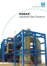
Storage Tank<br />
HOBAS produces process equipment up to a diameter of DN 4000. Thanks to the flexible production process,<br />
rectangular, round and asymmetric designs can be manufactured to the HOBAS Company Standards with almost<br />
no limitation to size. According to customer demands as well as special technical and operational requirements,<br />
even complex designs with GRP Composites Thermoplastics or pure GRP with a chemical protection layer can be<br />
developed.<br />
All figures quoted are values and may slightly vary due to manufacturing tolerances. The information and recommendations reflect the state of our knowledge at the time of publication/update. Therefore the provided data cannot be construed as an express or<br />
implied warranty. All details must be checked and if necessary agreed to in each individual case. HOBAS cannot accept any liability. This also applies to errors, omissions and changes to technical data without notice.<br />
22<br />
D41
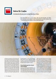
Absorber<br />
Example product: Flue gas scrubber, CMI-UVK GmbH Germany<br />
The absorber or gas scrubber is a technical device that merges gas with a liquid in order to dissolve the components of<br />
the gas and absorb them with the liquid. It usually consists of several parts and reaction zones. HOBAS produces<br />
absorbers according to customer requirements, with chemically resistant GRP, with or without thermoplastic liner.<br />
All figures quoted are values and may slightly vary due to manufacturing tolerances. The information and recommendations reflect the state of our knowledge at the time of publication/update. Therefore the provided data cannot be construed as an express or<br />
implied warranty. All details must be checked and if necessary agreed to in each individual case. HOBAS cannot accept any liability. This also applies to errors, omissions and changes to technical data without notice.<br />
23<br />
D42
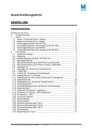
Cyclone<br />
Example product: Cyclone, Wacker Chemie AG Germany<br />
Cyclones are funnel-shaped and used for removing particles from a gas stream. Since the particles are continuously<br />
striking the inner cyclone walls, the material has to be especially abrasion resistant. Thanks to the excellent strength and<br />
chemical resistance of GRP, HOBAS <strong>Pipe</strong> <strong>Systems</strong> and Tanks are especially suited for this application. HOBAS produces<br />
customer-shaped cyclone systems with GRP or GRP Composites with thermoplastic liner.<br />
All figures quoted are values and may slightly vary due to manufacturing tolerances. The information and recommendations reflect the state of our knowledge at the time of publication/update. Therefore the provided data cannot be construed as an express or<br />
implied warranty. All details must be checked and if necessary agreed to in each individual case. HOBAS cannot accept any liability. This also applies to errors, omissions and changes to technical data without notice.<br />
24<br />
D43
GRP Header<br />
Example product: Catholyte Header for chlorine electrolysis, UHDE GmbH Germany<br />
The term Header refers to storage tanks in the range of chemical process lines. The safe storage and transport of the<br />
highly aggressive reactive products of the chloralkali process – chlorine and caustic soda solution – calls for such<br />
chemically resistant tanks and pipe systems, which can withstand the process-related temperatures and pressures.<br />
HOBAS manufactures process equipment up to a diameter of DN 4000 and pressure classes up to PN 40 according to<br />
customer requirements. For particularly aggressive media, HOBAS Tanks and <strong>Pipe</strong>s are provided with a thermoplastic<br />
liner.<br />
All figures quoted are values and may slightly vary due to manufacturing tolerances. The information and recommendations reflect the state of our knowledge at the time of publication/update. Therefore the provided data cannot be construed as an express or<br />
implied warranty. All details must be checked and if necessary agreed to in each individual case. HOBAS cannot accept any liability. This also applies to errors, omissions and changes to technical data without notice.<br />
25<br />
D44
<strong>Pipe</strong> Spool Manufacture<br />
Spools consists of various pipe components and accessories that are pre-assembled by HOBAS. Prefabricated spools help<br />
to save on costs and time at the installation of pipe systems and fully exploit the factory potentials for increasing quality<br />
standards. HOBAS produces spools in compliance with isometric plans, which are either provided by the customer or<br />
prepared by the HOBAS Engineers in accordance with the local requirements.<br />
All figures quoted are values and may slightly vary due to manufacturing tolerances. The information and recommendations reflect the state of our knowledge at the time of publication/update. Therefore the provided data cannot be construed as an express or<br />
implied warranty. All details must be checked and if necessary agreed to in each individual case. HOBAS cannot accept any liability. This also applies to errors, omissions and changes to technical data without notice.<br />
26<br />
D45
Material Specifications<br />
According to requirements and design, HOBAS Industrial <strong>Pipe</strong> <strong>Systems</strong> are characterized by the following data<br />
(further details on request):<br />
Physical properties<br />
Density<br />
Glass content<br />
Tensile strength (tengential)<br />
Tensile strength (axial)<br />
Mean linear thermal expansion coefficient<br />
Poisson's ratio<br />
Flexural elastic modulus<br />
Surface resistance (standard)<br />
Surface resistance (electrically conductive)<br />
Heat deflection temperature<br />
Thermal conductivity<br />
Points of reference for different pipe types up to 50 °C<br />
1,5 bis 2,0 g/cm³<br />
25-65 % vol.<br />
80 - 360 N/mm²<br />
80 - 200 N/mm²<br />
20 - 30 x 10-6 1/K<br />
0,25 - 0,35<br />
8000 - 20.000 N/mm²<br />
10 12 �<br />
� 10 5 �<br />
> 200 °C<br />
0,25 W/mK<br />
All figures quoted are values and may slightly vary due to manufacturing tolerances. The information and recommendations reflect the state of our knowledge at the time of publication/update. Therefore the provided data cannot be construed as an express or<br />
implied warranty. All details must be checked and if necessary agreed to in each individual case. HOBAS cannot accept any liability. This also applies to errors, omissions and changes to technical data without notice.<br />
30<br />
F41
Notes
HOBAS Engineering Austria<br />
Pischeldorfer Straße 128<br />
9020 Klagenfurt | Austria<br />
T +43.4264.28 52<br />
F +43.4264.28 52.2045<br />
info@hobas.com<br />
www.hobas.com<br />
HOBAS Group Worldwide<br />
HOBAS manufactures and markets HOBAS GRP <strong>Pipe</strong><br />
<strong>Systems</strong>. The HOBAS Network includes HOBAS <strong>Product</strong>ion<br />
Facilities and Sales Organizations in Europe<br />
and throughout the world.<br />
We develop and manufacture HOBAS <strong>Product</strong>s<br />
conserving nature‘s resources and with respect for<br />
our environment. Visit our website to find out more<br />
about the HOBAS Environmental Policy.