Submittal 5509QT Hydrant - Jay R. Smith MFG Co.
Submittal 5509QT Hydrant - Jay R. Smith MFG Co.
Submittal 5509QT Hydrant - Jay R. Smith MFG Co.

Create successful ePaper yourself
Turn your PDF publications into a flip-book with our unique Google optimized e-Paper software.
S<br />
DRAWN BY: CHECKED BY: APPROVED BY: SCALE: SIZE DRAWING NUMBER<br />
JLO<br />
DATE:<br />
5/23/90<br />
<strong>5509QT</strong> J.McD. T.D.<br />
NONE<br />
A<br />
S<strong>5509QT</strong><br />
DIMENSIONS ARE SUBJECT TO MANUFACTURERS TOLERANCE AND CHANGE WITHOUT NOTICE WE CAN ASSUME NO RESPONSIBILITY FOR USE OF SUPERSEDED OR VOID DATA<br />
SMITH ®<br />
CUSTOMER<br />
DRIVEN<br />
JAY R.<br />
SMITH <strong>MFG</strong>. CO. ®<br />
MEMBER OF MORRIS GROUP INTERNATIONAL<br />
POST OFFICE BOX 3237<br />
MONTGOMERY, ALABAMA 36109-0237 (USA)<br />
TEL: 334-277-8520 FAX: 334-272-7396 www.jrsmith.com<br />
Add 1/4" (6) When<br />
Optional Box for<br />
Material is Specified<br />
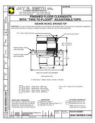
FIG. <strong>5509QT</strong><br />
LOCATION<br />
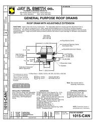
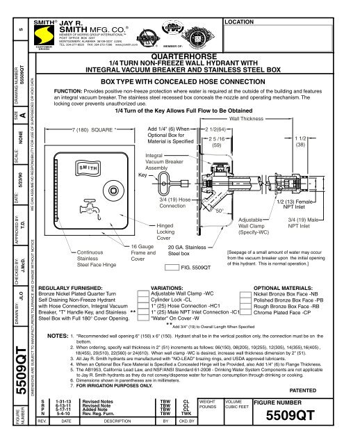
QUARTERHORSE<br />
1/4 TURN NON-FREEZE WALL HYDRANT WITH<br />
INTEGRAL VACUUM BREAKER AND STAINLESS STEEL BOX<br />
BOX TYPE WITH CONCEALED HOSE CONNECTION<br />
FUNCTION: Provides positive non-freeze protection where water is required at the outside of the building and features<br />
an integral vacuum breaker. The stainless steel recessed box conceals the nozzle and operating mechanism. The<br />
locking cover prevents unauthorized use.<br />
1/4 Turn of the Key Allows Full Flow to Be Obtained<br />
7 (180) SQUARE *<br />
M S<br />
I TH<br />
UPC<br />
<strong>Co</strong>ntinuous<br />
Stainless<br />
Steel Face Hinge<br />
REGULARLY FURNISHED:<br />
Bronze Nickel Plated Quarter Turn<br />
Self Draining Non-Freeze <strong>Hydrant</strong><br />
with Hose <strong>Co</strong>nnection, Integral Vacuum<br />
Breaker, "T" Handle Key, and Stainless<br />
Steel Box with Full 180° <strong>Co</strong>ver Opening.<br />
**<br />
ASPE<br />
Integral<br />
Vacuum Breaker<br />
Assembly<br />
Key<br />
16 Gauge<br />
Frame and<br />
<strong>Co</strong>ver<br />
®<br />
3/4 (19) Hose<br />
<strong>Co</strong>nnection<br />
Hinged<br />
Locking<br />
<strong>Co</strong>ver<br />
VARIATIONS:<br />
Adjustable Wall Clamp -WC<br />
Cylinder Lock -CL<br />
1" (25) Hose <strong>Co</strong>nnection -HC1<br />
1" (25) Male NPT Inlet <strong>Co</strong>nnection -IC1<br />
"Water" On <strong>Co</strong>ver -W<br />
*<br />
®<br />
MEMBER OF:<br />
2 1/2(64)<br />
2 5 /16<br />
(59)<br />
*Add 3/4" (19) to Overall Length When Specified<br />
[Seepage of a small amount of water may occur<br />
from the vacuum breaker upon the initial opening<br />
of this hydrant. This is normal operation.]<br />
OPTIONAL MATERIALS:<br />
Nickel Bronze Box Face -NB<br />
Polished Bronze Box Face -PB<br />
Rough Bronze Box Face -RB<br />
Chrome Plated Face -CP<br />
NOTES: 1. *Recommended wall opening 6" (150) x 6" (150). <strong>Hydrant</strong> shall be in the vertical position only, the connection must be on the<br />
bottom.<br />
2. When ordering, specify wall thickness in 2" (51) increments as follows: 06(150), 08(205), 10(255), 12(305), 14(355),16(405) ,<br />
18(455), 20(510), 22(560) or 24(610). When wall clamp -WC is desired, increase wall thickness dimension by 2" (51).<br />
3. All <strong>Jay</strong> R. <strong>Smith</strong> hydrants are manufactured with "NO-LEAD" brazing rings, and USDA approved lubricants.<br />
4. When an Optional Box Face Material is Specified a <strong>Co</strong>ncealed Hinge will be Provided, also Add 1/4" (6) to Flange Thickness.<br />
5. The AB1953, California Lead Law, and NSF/ANSI Standard 61-2008 - Drinking Water System <strong>Co</strong>mponents are not applicable<br />
to <strong>Jay</strong> R. <strong>Smith</strong> hydrants as they do not convey/dispense water for human consumption through drinking or cooking.<br />
6. Dimensions shown in parentheses are in millimeters.<br />
7. FOR IRRIGATION PURPOSES ONLY.<br />
PATENTED<br />
SANITARY<br />
E N G I N E E R I N G<br />
Prevention Rather Than Cure<br />
20 GA. Stainless<br />
Steel box<br />
50°<br />
Wall Thickness<br />
Adjustable<br />
Wall Clamp<br />
(Specify-WC)<br />
1 1/2<br />
(38)<br />
1/2 (13) Female<br />
NPT Inlet<br />
3/4 (19) Male<br />
NPT Inlet<br />
FIGURE<br />
NUMBER<br />
S 1-31-13 Revised Notes TBW CL<br />
R 6-13-11 Revised Note TBW CL<br />
P 5-17-11 Added Note TBW CL<br />
N 5-4-10 Rev. Reg. Furn. TBW TWK<br />
REV. DATE DESCRIPTION BY CKD. BY<br />
WEIGHT<br />
POUNDS<br />
VOLUME<br />
CUBIC FEET<br />
FIGURE NUMBER<br />
<strong>5509QT</strong>
DRAWING NUMBER<br />
F<br />
BS TD NONE S<strong>5509QT</strong>BS<br />
DRAWN BY: CHECKED BY: APPROVED BY: SCALE: SIZE<br />
DATE:<br />
<strong>5509QT</strong>-BS EMB 1-3-90<br />
A<br />
FIGURE<br />
NUMBER<br />
DIMENSIONS ARE SUBJECT TO MANUFACTURERS TOLERANCE AND CHANGE WITHOUT NOTICE WE CAN ASSUME NO RESPONSIBILITY FOR USE OF SUPERSEDED OR VOID DATA<br />
SMITH ®<br />
CUSTOMER<br />
DRIVEN<br />
JAY R.<br />
SMITH <strong>MFG</strong>. CO. ®<br />
MEMBER OF MORRIS GROUP INTERNATIONAL<br />
POST OFFICE BOX 3237<br />
MONTGOMERY, ALABAMA 36109-0237 (USA)<br />
TEL: 334-277-8520 FAX: 334-272-7396 www.jrsmith.com<br />
7<br />
8<br />
REV. DATE DESCRIPTION BY CKD. BY<br />
9<br />
12<br />
12a<br />
12b<br />
12c<br />
12d<br />
12e<br />
WEIGHT<br />
POUNDS<br />
LOCATION<br />
VOLUME<br />
CUBIC FEET<br />
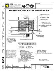
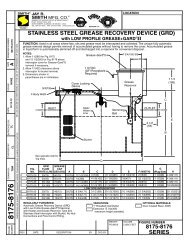
Vacuum Breaker<br />
Assembly<br />
3 7 11 1a 14 13h 1b 13 1c<br />
*<br />
11<br />
∆<br />
∆ These Replacement Parts Available<br />
in HPRK-7<br />
* All Parts Accessible from Face of<br />
<strong>Hydrant</strong> by Removing Face Nut.<br />
* 9<br />
∆<br />
*<br />
8<br />
∆<br />
ASPE<br />
*<br />
13h<br />
∆<br />
*<br />
10<br />
NO. DESCRIPTION<br />
1 Head/Casing Assembly<br />
1a Head<br />
1b Casing<br />
1c Valve Housing<br />
3 Key<br />
7 Face Nut<br />
8 Actuator Shaft<br />
9 Actuator "O" Ring<br />
F 5-21-92 Changed Repair Pts. TWK JCS<br />
E 10-25-91 Update Figure Number TWK JCS<br />
D 12-90 Rev Dwg EMB JCS<br />
C 12-21-90 Added HPRK-7VB Note CMB JCS<br />
®<br />
®<br />
MEMBER OF:<br />
SANITARY<br />
E N G I N E E R I N G<br />
Prevention Rather Than Cure<br />
HYDRANT PARTS LIST<br />
*<br />
13h<br />
∆<br />
*<br />
13a<br />
∆<br />
*<br />
13b<br />
∆<br />
*<br />
13c<br />
∆<br />
HYDRANT PARTS LIST<br />
NO. DESCRIPTION<br />
10 Operator Rod<br />
11 Face Nut Washer<br />
12 Vacuum Breaker Assembly<br />
12a VB Cap<br />
12b VB Body<br />
12c VB Washer<br />
12d VB "O" Ring<br />
12e VB Piston<br />
13 Valve Body Assembly<br />
*<br />
13d<br />
∆<br />
13h<br />
*<br />
13e<br />
∆<br />
*<br />
13f<br />
∆<br />
FIGURE NUMBER<br />
*<br />
13g<br />
∆<br />
NO. DESCRIPTION<br />
13a Retaining Ring<br />
13b Valve Body<br />
13c Valve Actuator<br />
13d Nylon Thrust Washer<br />
13e Rotating Ceramic Disc<br />
13f Fixed Ceramic Disc<br />
13g Silicon Rubber Seal<br />
13h Retainer Guide (2)<br />
14 Box Assembly S.S.<br />
<strong>5509QT</strong>