ROSTA OSCILLATING MOUNTINGS - Jens S Transmisjoner
ROSTA OSCILLATING MOUNTINGS - Jens S Transmisjoner
ROSTA OSCILLATING MOUNTINGS - Jens S Transmisjoner

Create successful ePaper yourself
Turn your PDF publications into a flip-book with our unique Google optimized e-Paper software.
<strong>ROSTA</strong><br />
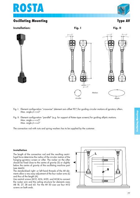
Oscillating Mounting<br />
Type AV<br />
Installation: Fig. I Fig. II<br />
= ± 2°<br />
= ± 5°<br />
= ± 2°<br />
A<br />
= ± 2°<br />
Motion:<br />
circular<br />
elliptic<br />
Fig. I:<br />
Element configuration “crosswise” (element axis offset 90°) for guiding circular motions of gyratory sifters.<br />
Max. angle = ± 2°<br />
Fig. II: Element configuration “parallel” (e.g. for support of Rotex-type screens) for guiding elliptic motions.<br />
Max. angle = ± 5°<br />
Max. angle = ± 2°<br />
The connection rod with nuts and spring washers has to be supplied by the customer.<br />
Oscillating Mountings<br />
Installation<br />
The length of the connection rod and the resulting centrifugal<br />
force determine the radius of the circular motion of the<br />
hanging gyratory screen or sifter. The rocker on the sifter<br />
should be fixed close to the centre of gravity (S) or slightly<br />
below the centre of gravity of the oscillating machine part<br />
(see sketch).<br />
The standardised right- or left-hand threads of the AV elements<br />
allow a very easy adjustment of the four rocker arms (L)<br />
and thus of the length (A).<br />
Use central screws (M12, M16, M20, and M24) to connect<br />
the rocker arm and the ceiling structure for elements sizes<br />
AB 18, 27, 38 and 45. For the AV 50 size use four M12<br />
screws on both ends.<br />
77