0530, 0630,0641, 0830, 0840,1030 50 Hz & 60 Hz Installation and ...
0530, 0630,0641, 0830, 0840,1030 50 Hz & 60 Hz Installation and ...
0530, 0630,0641, 0830, 0840,1030 50 Hz & 60 Hz Installation and ...

You also want an ePaper? Increase the reach of your titles
YUMPU automatically turns print PDFs into web optimized ePapers that Google loves.
AS<br />
<strong>0530</strong>, <strong>0630</strong>,<strong>0641</strong>, <strong>0830</strong>, <strong>0840</strong>,<strong>1030</strong><br />
<strong>50</strong> <strong>Hz</strong> & <strong>60</strong> <strong>Hz</strong><br />
<strong>Installation</strong> <strong>and</strong> operating instructions<br />
We reserve the right to make modifications in the interest of technical development<br />
(4) 1597<strong>50</strong>45 GB 07/01
AS<br />
1 General.....................................................................................................................1<br />
1.1 Application areas.......................................................................................................1<br />
1.1.1 Approvals for explosion-proof pumps .......................................................................1<br />
1.1.2 Particular comments on the use of explosion-proof<br />
pumps in explosive zones .........................................................................................1<br />
1.1.3 Commentary on the regulations in DIN 1986 for the<br />
use of lifting stations of the pumping of effluent<br />
containing faecal matter ............................................................................................1<br />
1.2 Technical data...........................................................................................................2<br />
1.2.1 Nameplate ................................................................................................................2<br />
1.2.2 Technical data ..........................................................................................................3<br />
1.2.3 Dimensions................................................................................................................4<br />
2 Safety........................................................................................................................5<br />
3 Transport..................................................................................................................6<br />
4 Product description ................................................................................................6<br />
4.1 Accessories ..............................................................................................................7<br />
5 Set up <strong>and</strong> installation . ..........................................................................................8<br />
5.1 <strong>Installation</strong> example, concrete sump .........................................................................8<br />
5.2 Discharge line............................................................................................................9<br />
5.3 Electrical connection .................................................................................................10<br />
5.3.1 Checking direction of rotation....................................................................................12<br />
5.3.2 Changing direction of rotation ..................................................................................12<br />
6 Commissioning .......................................................................................................13<br />
7 Maintenance ............................................................................................................13<br />
7.1 General maintenance hints .......................................................................................14<br />
7.2 Commentary on maintenance of lifting stations<br />
in accordance with DIN 1986, part 31 ......................................................................14<br />
7.3 Oil fill <strong>and</strong> oil change .................................................................................................15<br />
7.4 Cleaning ....................................................................................................................15<br />
7.5 Venting of the volute .................................................................................................15
AS<br />
1 General<br />
1.1 Application areas<br />
ABS submersible pumps of the AS series have been designed for the economical <strong>and</strong><br />
reliable pumping of effluent in commercial, industrial <strong>and</strong> municipal applications. The<br />
submersible pumps of the AS series are suitable for clear water, waste water <strong>and</strong> for sewage<br />
containing solid or fibrous particles <strong>and</strong> for effluent containing faecal matters <strong>and</strong> sludge.<br />
The AS series is suitable for modern sewage installation systems.<br />
1.1.1 Explosion-proof Approvals<br />
The motors of the AS series have explosion-proof certification in accordance with<br />
EEx d llB T4<br />
1.1.2 Particular comments on the use of explosion-proof pumps in explosive zones.<br />
1. Explosion-proof submersible pumps may only be operated with the thermal<br />
sensing system connected.<br />
2. If ball type float switches are used, these must be connected to an<br />
intrinsically safe electrical circuit “Protection type EX (i)” in accordance with<br />
VDE 0165.<br />
3. Dismantling <strong>and</strong> repair of submersible explosion-proof motors may only be<br />
carried out by approved personnel in specially approved work shops.<br />
1.1.3 Commentary on the regulations in DIN 1986 for the use of lifting stations of the<br />
pumping of effluent containing faecal matter.<br />
Automatically operated lifting units are prescribed if:<br />
- The water level in the odour-lock lies below the sewer backwash level.<br />
- Rainwater gullies from areas below the sewer backwash level are present.<br />
The sewer backwash level is the maximum possible water level in the public sewer network,<br />
<strong>and</strong> information on this can be obtained from your Local Authority. If the backwash level has<br />
not been fixed by the Local Authority, then the surface level of the roadway at the connection<br />
point is taken to be the level.<br />
If the effluent does not give rise to foul odours, then a water-tight connection tank fitted with a<br />
lid is acceptable.<br />
ATTENTION The Regulations of DIN 1986 as well as your own local by-laws<br />
should be observed.<br />
1
AS<br />
1.2 Technical Data<br />
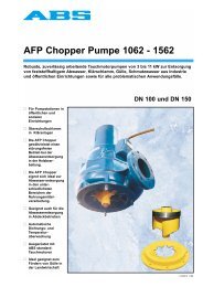
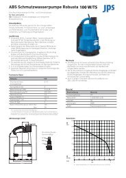
1.2.1 Nameplate<br />
We recommend that you record the data from the original nameplate on the nameplate<br />
illustration below <strong>and</strong> maintain it, together with your purchase receipt, as a proof for<br />
subsequent use.<br />
Always state the pump type <strong>and</strong> the item no. <strong>and</strong> serial no. in the field "Nr" in all<br />
Communications.<br />
Fig. 1 Nameplate St<strong>and</strong>ard Version<br />
Fig. 2 Nameplate EX Version<br />
2<br />
Legend<br />
Type Pump type<br />
Nr. Item No./Serial No.<br />
UN Rated Voltage V<br />
IN Rated Current A<br />
Frequency <strong>Hz</strong><br />
P1N Rated Input Power kW<br />
P2N<br />
n<br />
Rated Output Power<br />
Speed<br />
kW<br />
min -1<br />
QN Rated discharge m 3 /h<br />
HN Rated Head m<br />
LRØ<br />
Qmax<br />
Impeller diameter<br />
Max. Flow<br />
mm<br />
m 3 /h<br />
Hmax Max. Head m<br />
DN Discharge diameter mm<br />
�� Water pressure tight<br />
IP 68 Protection type<br />
Z-Nr Test No. of the<br />
Institute of Building<br />
Technology, Berlin.
AS<br />
1.2.2 Technical Data<br />
AS <strong>50</strong> <strong>Hz</strong><br />
Pump Type Imp Ø<br />
mm<br />
Motor Power*<br />
P1 P2<br />
kW kW<br />
Speed<br />
at<br />
<strong>50</strong><strong>Hz</strong><br />
min -1<br />
Rated<br />
voltage<br />
V<br />
3<br />
Rated<br />
current<br />
A<br />
Cable<br />
type**<br />
St<strong>and</strong> Ex<br />
Max<br />
head<br />
m<br />
Max<br />
flow<br />
m 3 /h<br />
Weight***<br />
AS <strong>0530</strong> S12/2 W 110 1.8 1.2 2900 230 8.2 (1) (2) 12.2 25 34<br />
AS <strong>0530</strong> S12/2 D 110 1.7 1.2 2900 400 3.3 (1) (2) 12.2 25 34<br />
AS <strong>0530</strong> S17/2 D 125 2.3 1.7 2900 400 4.0 (1) (2) 16.0 36 34<br />
AS <strong>0530</strong> S26/2 D 142 3.4 2.6 2900 400 5.6 (1) (2) 21.0 34 40<br />
AS <strong>0630</strong> S10/4 W 130 1.7 1.0 14<strong>50</strong> 230 7.5 (1) (2) 5.5 36 37<br />
AS <strong>0630</strong> S10/4 W 1<strong>60</strong> 1.7 1.0 14<strong>50</strong> 230 7.5 (1) (2) 5.5 47 37<br />
AS <strong>0630</strong> S13/4 D 130 1.9 1.3 14<strong>50</strong> 400 3.6 (1) (2) 5.5 35 37<br />
AS <strong>0630</strong> S13/4 D 1<strong>60</strong> 1.9 1.3 14<strong>50</strong> 400 3.6 (1) (2) 5.3 54 37<br />
AS <strong>0630</strong> S13/4 D 186 1.9 1.3 14<strong>50</strong> 400 3.6 (1) (2) 9.0 46 37<br />
AS <strong>0630</strong> S22/4 D 205 2.9 2.2 14<strong>50</strong> 400 5.2 (1) (2) 10.6 70 42<br />
AS <strong>0641</strong> S30/2 D 143 3.6 3.0 2900 400 6.2 (1) (2) 28 70 42<br />
AS <strong>0830</strong> S10/4 W 130 1.7 1.0 14<strong>50</strong> 230 7.5 (1) (2) 5.5 36 40<br />
AS <strong>0830</strong> S10/4 W 1<strong>60</strong> 1.7 1.0 14<strong>50</strong> 230 7.5 (1) (2) 7.0 47 40<br />
AS <strong>0830</strong> S13/4 D 130 1.9 1.3 14<strong>50</strong> 400 3.6 (1) (2) 4.7 35 40<br />
AS <strong>0830</strong> S13/4 D 1<strong>60</strong> 1.9 1.3 14<strong>50</strong> 400 3.6 (1) (2) 7.0 54 40<br />
AS <strong>0830</strong> S13/4 D 186 1.9 1.3 14<strong>50</strong> 400 3.6 (1) (2) 9.0 46 40<br />
AS <strong>0830</strong> S22/4 D 205 2.9 2.2 14<strong>50</strong> 400 5.2 (1) (2) 10.6 69 42<br />
AS <strong>0840</strong> S12/2 W 110 1.8 1.2 2900 230 8.2 (1) (2) 6.7 34 35<br />
AS <strong>0840</strong> S12/2 W 118 1.8 1.2 2900 230 8.2 (1) (2) 11.2 51 35<br />
AS <strong>0840</strong> S12/2 D 110 1.7 1.2 2900 400 3.3 (1) (2) 6.7 34 35<br />
AS <strong>0840</strong> S12/2 D 118 1.7 1.2 2900 400 3.3 (1) (2) 11.2 51 35<br />
AS <strong>0840</strong> S17/2 D 128 2.3 1.7 2900 400 4.0 (1) (2) 14.6 55 35<br />
AS <strong>0840</strong> S26/2 D 142 3.4 2.6 2900 400 5.6 (1) (2) 19.8 67 40<br />
AS <strong>1030</strong> S22/4 D 205 2.9 2.2 14<strong>50</strong> 400 5.2 (1) (2) 10.6 70 42<br />
*** Weight with 10m cable Cable type** (1) Special rubber 4G1,5 (∅ 17.0 mm)<br />
W = Single phase; D = Three phase (2) Special rubber 7G1,5 (∅ 10.9 mm)<br />
∗ P1 = Power taken from mains; P2 = Power at motor shaft.<br />
AS <strong>60</strong> <strong>Hz</strong><br />
Pump Type Imp Ø<br />
mm<br />
Motor Power*<br />
P1 P2<br />
kW kW<br />
Speed<br />
at<br />
<strong>60</strong><strong>Hz</strong><br />
min -1<br />
Rated<br />
voltage<br />
V<br />
Rated<br />
current<br />
A<br />
Cable<br />
type**<br />
St<strong>and</strong> Ex<br />
Max<br />
head<br />
m<br />
Max<br />
flow<br />
m 3 /h<br />
kg<br />
Weight***<br />
AS <strong>0530</strong> S16/2 W 98 2.1 1.6 34<strong>50</strong> 230 9.2 (1) (2) 14.8 24.9 34<br />
AS <strong>0530</strong> S16/2 D 98 2.2 1.6 34<strong>50</strong> 4<strong>60</strong> 3.3 (1) (2) 14.8 24.9 34<br />
AS <strong>0530</strong> S18/2 W 108 2.5 1.8 34<strong>50</strong> 230 10.8 (1) (2) 17.9 24.9 34<br />
AS <strong>0530</strong> S18/2 D 108 2.4 1.8 34<strong>50</strong> 4<strong>60</strong> 3.6 (1) (2) 18.6 20 34<br />
AS <strong>0530</strong> S30/2 D 125 3.9 3.0 34<strong>50</strong> 4<strong>60</strong> 5.5 (1) (2) 22.5 35.7 40<br />
AS <strong>0630</strong> S10/4 W 130 1.5 1.0 17<strong>50</strong> 230 6.5 (1) (2) 6.5 <strong>50</strong>.3 37<br />
AS <strong>0630</strong> S16/4 D 1<strong>60</strong> 2.2 1.6 17<strong>50</strong> 4<strong>60</strong> 3.6 (1) (2) 10.3 4.6 37<br />
AS <strong>0630</strong> S25/4 D 175 3.2 2.5 17<strong>50</strong> 4<strong>60</strong> 4.9 (1) (2) 12.5 70.3 37<br />
AS <strong>0641</strong> S35/2 D 134 3.5 4.3 34<strong>50</strong> 400 6.1 (1) (2) 35.4 69.3 42<br />
AS <strong>0830</strong> S10/4 W 130 1.5 1.0 17<strong>50</strong> 230 6.5 (1) (2) 6.5 <strong>50</strong>.3 40<br />
AS <strong>0830</strong> S10/4 D 130 1.5 1.0 17<strong>50</strong> 4<strong>60</strong> 6.5 (1) (2) 6.5 46 40<br />
AS <strong>0830</strong> S16/4 D 1<strong>60</strong> 2.2 1.6 17<strong>50</strong> 4<strong>60</strong> 3.6 (1) (2) 10.3 46 40<br />
AS <strong>0830</strong> S25/4 D 175 3.2 2.5 17<strong>50</strong> 4<strong>60</strong> 4.9 (1) (2) 12.3 70.3 42<br />
AS <strong>0840</strong> S16/2 W 110 2.1 1.6 34<strong>50</strong> 230 9.2 (1) (2) 10.4 43.7 35<br />
AS <strong>0840</strong> S16/2 D 110 2.2 1.6 34<strong>50</strong> 4<strong>60</strong> 3.3 (1) (2) 10.4 44 35<br />
AS <strong>0840</strong> S18/2 W 118 2.5 1.8 34<strong>50</strong> 230 10.8 (1) (2) 15 49.7 35<br />
AS <strong>0840</strong> S18/2 D 118 2.4 1.8 34<strong>50</strong> 4<strong>60</strong> 3.6 (1) (2) 15 52 35<br />
AS <strong>0840</strong> S30/2 D 128 3.9 3.0 34<strong>50</strong> 4<strong>60</strong> 5.5 (1) (2) 21.3 62.8 40<br />
AS <strong>1030</strong> S25/4 D 175 3.2 2.5 17<strong>50</strong> 4<strong>60</strong> 4.9 (1) (2) 12.5 70.3 37<br />
*** Weight with 10m cable Cable type** (1) Special rubber 4G1,5 (∅ 17.0 mm)<br />
W = Single phase; D = Three phase (2) Special rubber 7G1,5 (∅ 10.9 mm)<br />
∗ P1 = Power taken from mains; P2 = Power at motor shaft.<br />
kg
AS<br />
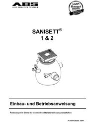
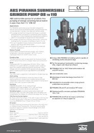
1.2.3 Dimensions<br />
AS <strong>0630</strong>, AS<strong>0830</strong>, AS<strong>1030</strong>, AS<strong>0641</strong> AS <strong>0840</strong> AS <strong>0530</strong><br />
XX Lowest switch-out point for automatic operation XX Lowest switch-out point for automatic operation XX Lowest switch-out point for automatic operation<br />
Dimensional Table AS <strong>50</strong> <strong>Hz</strong> Dimensional Table AS <strong>60</strong> <strong>Hz</strong><br />
Pump Type A B C D E F Pump Type A B C D E F<br />
AS <strong>0530</strong> S12/2 432 292 100 125 90 188 AS <strong>0530</strong> S16/2 432 292 100 125 90 188<br />
AS <strong>0530</strong> S17/2 432 292 100 125 90 188 AS <strong>0530</strong> S18/2 432 292 100 125 90 188<br />
AS <strong>0530</strong> S26/2 444 292 100 125 90 188 AS <strong>0530</strong> S30/2 444 292 100 125 90 188<br />
AS <strong>0630</strong> S10/4 437 307 57 140 132 140 AS <strong>0630</strong> S10/4 437 307 57 140 132 140<br />
AS <strong>0630</strong> S13/4 437 307 57 140 132 140 AS <strong>0630</strong> S16/4 437 307 57 140 132 140<br />
AS <strong>0630</strong> S22/4 4<strong>50</strong> 307 57 140 132 140 AS <strong>0630</strong> S25/4 4<strong>50</strong> 307 57 140 132 140<br />
AS <strong>0641</strong> S30/2 428 270 54 140 132 172 AS <strong>0641</strong> S35/2 428 270 54 140 132 172<br />
AS <strong>0830</strong> S10/4 437 307 88 200 167 200 AS <strong>0830</strong> S10/4 437 307 88 200 167 200<br />
AS <strong>0830</strong> S13/4 437 307 88 200 167 200 AS <strong>0830</strong> S16/4 437 307 88 200 167 200<br />
AS <strong>0830</strong> S22/4 4<strong>50</strong> 307 88 200 167 200 AS <strong>0830</strong> S25/4 4<strong>50</strong> 307 88 200 167 200<br />
AS <strong>0840</strong> S12/2 418 2<strong>50</strong> 88 200 167 200 AS <strong>0840</strong> S16/2 418 2<strong>50</strong> 88 200 167 200<br />
AS <strong>0840</strong> S17/2 418 2<strong>50</strong> 88 200 167 200 AS <strong>0840</strong> S18/2 418 2<strong>50</strong> 88 200 167 200<br />
AS <strong>0840</strong> S26/2 430 2<strong>50</strong> 88 200 167 200 AS <strong>0840</strong> S30/2 430 2<strong>50</strong> 88 200 167 200<br />
AS <strong>1030</strong> S22/4 4<strong>50</strong> 307 92 225 180 225 AS <strong>1030</strong> S25/4 4<strong>50</strong> 307 92 225 180 225<br />
St<strong>and</strong>ard execution is with 10m cable with free cable ends.<br />
ATTENTION Maximum medium temperature for continuous operation with fully<br />
submerged unit = 40°C, intermittent <strong>60</strong>°C.<br />
4
AS<br />
2. Safety<br />
(extracted from VDMA-St<strong>and</strong>ard<br />
Sheet 24292)<br />
These operating instructions<br />
contain basic information on the<br />
erection, operating <strong>and</strong><br />
maintenance <strong>and</strong> should be<br />
followed carefully. For this reason it<br />
is essential that these instructions<br />
are carefully read before erection or<br />
commissioning by both the<br />
installation crew as well as those<br />
responsible for operation or<br />
maintenance. The operating<br />
instructions should always be<br />
readily available at the location of<br />
the unit.<br />
In addition to following the safety<br />
regulations of a general nature<br />
listed under these main headings, it<br />
is also essential that the special<br />
safety instructions given under other<br />
headings be observed.<br />
2.1 Identification of Hints in<br />
the Operating obstructions<br />
Safety instructions<br />
given in this Operating<br />
Manual, the nonobservance<br />
of which<br />
could cause danger to<br />
life have been<br />
specifically high-lighted<br />
with the general danger<br />
symbol, safety signs in<br />
accordance with DIN<br />
4844-W 9.<br />
The presence of a<br />
dangerous voltage is<br />
identified with the safety<br />
symbol in accordance<br />
with DIN 4844-W 8.<br />
ATTENTION Applies to safety<br />
instructions, the<br />
non-observance of<br />
which could<br />
damage the unit or<br />
affect its<br />
functioning.<br />
Symbols directly on the unit itself,<br />
e.g.<br />
— direction of rotation arrow<br />
— nameplate<br />
must be carefully observed <strong>and</strong><br />
must be maintained in a legible<br />
condition.<br />
2.2 Qualifications of Personnel<br />
The personnel for maintenance,<br />
inspection <strong>and</strong> erection must<br />
possess the required qualifications<br />
for the work.<br />
2.3 Dangers which could arise<br />
due to non-observance of<br />
the safety instructions<br />
The non-observance of the safety<br />
instructions can lead to both danger<br />
to personnel <strong>and</strong> also to possible<br />
harm to the environment or the unit<br />
itself. Non-observance of the safety<br />
instructions can invalidate the rights<br />
of the user to any compensation or<br />
regress.<br />
In detail, non-observance can for<br />
example result in the following<br />
dangers:<br />
— Failure of important functions<br />
of the unit/installation<br />
— Danger to personnel by<br />
electrical, mechanical or<br />
chemical influences<br />
— Danger to the environment<br />
by leakage of dangerous<br />
substances.<br />
2.4 Carrying out work in a<br />
safety conscious manner<br />
The safety instructions listed in this<br />
Operating Manual, the existing<br />
National Regulations for Safety, as<br />
well as any internal operating or<br />
safety regulations which apply in the<br />
user's own premises must be<br />
observed.<br />
2.5 Safety Regulations for the<br />
Owner/Operator<br />
All dangers due to electricity must<br />
be avoided (for details consult the<br />
Regulations of your local Electricity<br />
Supply Company).<br />
2.6 Safety Regulations for<br />
maintenance, inspection<br />
<strong>and</strong> installation work<br />
The user of the unit should ensure<br />
that all maintenance, inspection or<br />
installation work is carried out by<br />
authorised <strong>and</strong> qualified skilled<br />
5<br />
personnel. The user must also<br />
make certain that they have<br />
carefully studied the operating<br />
instructions.<br />
In principle all work on the unit<br />
should only be carried out while it is<br />
stationary.<br />
Pumps or units, used for pumping<br />
of fluids which could be injurious to<br />
health must be decontaminated.<br />
After completion of the work all<br />
safety <strong>and</strong> protective devices must<br />
be refitted <strong>and</strong> a check should be<br />
made that they are fully functional.<br />
Before starting up again, the points<br />
listed under the section<br />
Commissioning should be complied<br />
with.<br />
2.7 Unilateral modification <strong>and</strong><br />
spare parts manufacturing<br />
Modifications or changes to the unit/<br />
installation should only be carried<br />
out after consultations with the<br />
manufacturer. Original spare parts<br />
<strong>and</strong> accessories authorised by the<br />
manufacturer are essential for<br />
compliance with safety<br />
requirements. The use of other<br />
parts can invalidate any claims for<br />
warranty or compensation.<br />
2.8 Unproved usage<br />
The operating safety of the unit is<br />
only guaranteed provided that the<br />
unit is used in accordance with the<br />
conditions listed in Section 1. The<br />
limit values given in the data sheet<br />
should under no circumstances be<br />
exceeded.<br />
These installation <strong>and</strong> operation<br />
instructions do not supersede or<br />
exclude the following of generally<br />
valid regulations <strong>and</strong> st<strong>and</strong>ards.<br />
VDMA = Verb<strong>and</strong> Deutscher Maschinenund<br />
Anlagenbau e.V<br />
(German Machinery Manufacturers<br />
Association)
AS<br />
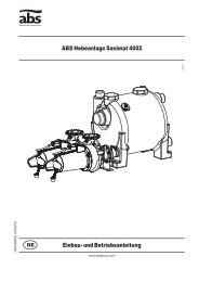
3 Transport<br />
During transport the submersible pump should not be dropped or thrown.<br />
The submersible pump should never be raised or lowered by the Power cable.<br />
The submersible pumps of the AS series are fixed with a lifting device to which a chain<br />
<strong>and</strong> shackle may be attached for transport or for suspension of the pump.<br />
Any hoist used must be adequately dimensioned for the weight<br />
of the pump.<br />
All relevant safety regulators as well as general good technical practice must be complied<br />
with.<br />
4. Product description<br />
The water tight fully flood-proof motor <strong>and</strong> the hydraulic section form a compact unit<br />
construction.<br />
The rotor shaft of all AS submersible pumps is supported by means of lubricated-for-life<br />
ball bearings.<br />
The shaft sealing on the medium side of all AS pumps is carried out by a high quality<br />
mechanical seal.<br />
The motors have been designed, depending on type, for single-phase <strong>and</strong> three-phase, 2<br />
<strong>and</strong> 4 -pole operation. The protection type is IP 68, the stator winding is Class F insulation<br />
(155°C).<br />
ATTENTION Explosion-proof pumps may only be used in explosive zones with the<br />
thermal sensors fitted (Leads: FO, F1).<br />
Depending on the layout in the control panel, the submersible pump may<br />
switch itself automatically back on after it has cooled down.<br />
6
AS<br />
4.1 Accessories<br />
Fixed <strong>Installation</strong> (wet) with ABS Automatic Coupling System<br />
Description (Material) Size Part No.<br />
(1) Pedestal with 90° Bend<br />
(GG-25 cast iron) for ABS<br />
2 ins. 623205<strong>60</strong><br />
Automatic Coupling System<br />
DN 65 62320673<br />
with DlN-flange fastening DN 80 62320649<br />
(3) Guide tube (steel galv.) 2” 1 m<br />
2 m<br />
3 m<br />
4 m<br />
5 m<br />
6 m<br />
O Discharge pipe on request, please give DN <strong>and</strong> L<br />
(4) Ball type non-return valve (GG-25)<br />
with inspection opening <strong>and</strong> venting<br />
mechanism including 1 set of bolts<br />
<strong>and</strong> 1 gasket, flanges to PN 16<br />
with 2½” (DN 65) threaded ends<br />
(5) Gate valve (GG-25 cast iron)<br />
including h<strong>and</strong> wheel, 1 set of<br />
bolts <strong>and</strong> 1 gasket, flanges to<br />
PN 16<br />
G 2 ins.<br />
DN 80<br />
2 ins.<br />
DN 65<br />
DN 80<br />
31380001<br />
31380002<br />
31380003<br />
31380004<br />
31380005<br />
31380006<br />
61400513<br />
61400543<br />
61400534<br />
14040007<br />
61420<strong>50</strong>0<br />
(6) 90° Bend, Q-piece, DN 80 626<strong>1030</strong>2<br />
(SG iron to DIN 28637)<br />
(7) Junction piece (St. 37 steel) to<br />
join the two discharge lines in<br />
the case of a twin-pump station<br />
(8) Chain (steel, galv.)<br />
including Shackle<br />
(9) Sump cover (St. 37 steel)<br />
with frame <strong>and</strong> seal<br />
DN 80/80/ 80<br />
DN 80/100/ 80<br />
<strong>50</strong>0x <strong>50</strong>0 mm<br />
700x 700 mm<br />
700x1400 mm<br />
62610001<br />
62610002<br />
m 14990002<br />
+ 14990008<br />
14990051<br />
14990052<br />
14990053<br />
7<br />
Synthetic Valves<br />
Description (Material) Size Part No.<br />
(3) Transition piece SUF 80/100 Sleeve 4"<br />
(Synthetic) in connection with (2) for connection of<br />
synthetic valves to ABS duckfoot pedestal DN 80,<br />
including 1 Quick clamping device SSR with profile seal<br />
(4) Ball type non-return valves SKV 100 with Sleeve 4"<br />
(Synthetic) with venting mechanism, including<br />
2 quick clamping devices SSR with profile seal<br />
(5) Shut-off bracket SAS 100 (Synthetic) Sleeve 4”<br />
including 1 quick clamping device SSR with profile seal<br />
<strong>and</strong> 1 flat gasket<br />
(6) Junction piece SV 100 (Synthetic) Sleeve 4"<br />
including 1 quick clamping device SSR with profile seal<br />
<strong>and</strong> 2 flat gaskets<br />
(7) Pipe bend SR 90°/100 (Synthetic) Sleeve 4"<br />
including 2 quick clamping devices SSR with profile seal<br />
<strong>and</strong> 1 flat gasket<br />
(8) Quick clamping device SSA 100<br />
including flat gasket for connecting of 1 valve to another<br />
valve<br />
(9) Quick clamping device SSR 100<br />
including profile seal <strong>and</strong> clampring for connecting a<br />
valve to a pipe<br />
(10) ABS Combination Valve System S 1 Sleeve 4”<br />
(Synthetic) for lifting stations<br />
with one pump consisting of:<br />
62540028<br />
61400553<br />
61420581<br />
62610041<br />
61090158<br />
61900020<br />
61900015<br />
61900017<br />
1 Ball type non-return valve SKV 100, 1 Shut-off valve SAS 100,<br />
2 Quick clamping devices SSR with 2 Profile seals, 1 Quick<br />
clamping device SSA, with 1 flat gasket<br />
(11) ABS Combination Valve System S 2 Sleeve 4”<br />
(Synthetic) for lifting stations<br />
61900018<br />
with two pumps consisting of:<br />
2 Ball type non-return valves SKV 100, 2 Shut-off valves SAS<br />
100, 1 Junction piece SV 100, 3 quick clamping devices SSR<br />
with 3 Profile seals, 4 quick clamping devices SSA with 3 Flat<br />
gaskets
AS<br />
5. Set up <strong>and</strong> <strong>Installation</strong><br />
ATTENTION All relevant regulations covering sewage pumping installations <strong>and</strong>, where<br />
applicable, explosion-proof installations must be complied with.<br />
The cable duct to the control panel should be made gas-tight by filling with<br />
foam after the power supply <strong>and</strong> control circuit cables have been laid.<br />
Particular attention must be paid to the safety regulations covering work in<br />
closed areas in sewage plants as well as good general technical practices.<br />
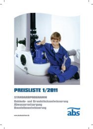
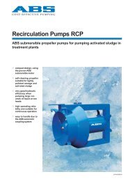
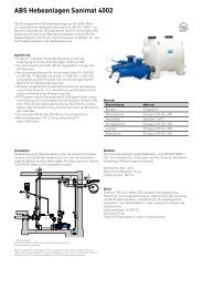
5.1 <strong>Installation</strong> example, concrete sump<br />
8<br />
1 Sump cover<br />
2 Venting line<br />
3 Sump cover<br />
4 Sleeve for cable<br />
protective duct to<br />
the control panel<br />
5 Chain<br />
6 Inflow line<br />
7 Ball type float switch<br />
8 Submersible pump<br />
9 Concrete sump.<br />
10 Pedestal<br />
11 Guide tube.<br />
12 Discharge line<br />
13 Non-return valve<br />
14 Gate valve<br />
15 Power cable to motor
AS<br />
5.2 Discharge Line<br />
The discharge line must be installed in compliance with the relevant regulations.<br />
Din 1986 applies in particular to the following:<br />
- The discharge line should be fitted with a backwash loop (180° bend) located<br />
above the backwash level <strong>and</strong> should then flow by gravity into the collection line<br />
or sewer.<br />
- The discharge line should not be connected to a down pipe.<br />
- No other inflows or discharge lines should be connected to this discharge line.<br />
ATTENTION The discharge line should be installed so that it is not affected by frost.<br />
.<br />
9
AS<br />
5.3 Electrical Connection<br />
Before starting operation, a qualified person should inspect the system to<br />
ensure that one of the required electrical protective measures has been<br />
provided. Earthing, Neutral line, earth leakage circuit breakers, etc., must<br />
comply with the regulations of the local power supply authority <strong>and</strong> their function<br />
should be checked by a qualified person. We recommend the use of a sensitive<br />
earth leakage circuit breaker (in accordance with VDE 0700, part 41 "safety of<br />
electrical appliances for domestic <strong>and</strong> other uses,” issue June '91).<br />
ATTENTION Cross section <strong>and</strong> voltage drop of the power supply cable must comply<br />
with VDE, <strong>and</strong> other local power supply regulations. The voltage specified<br />
on the pump nameplate must be the same as the supply voltage.<br />
The system must be protected by a fuse of adequate rating (in accordance with the rated<br />
power of the pump).<br />
Potential bonding must be carried out in a pump station in accordance with VDE 0190<br />
(regulations for the installation of pipelines, protective devices in electrical plants).<br />
In the case of pumps supplied as st<strong>and</strong>ard with a plug, an earthed socket must be<br />
installed above the possible flood level.<br />
In the case of pumps not supplied with a plug, the following applies:<br />
The power supply <strong>and</strong> pump cable must be connected to the terminals of the<br />
control panel in accordance with the designations provided by a qualified<br />
person in compliance with local regulations.<br />
An overload switch must be fitted.<br />
ATTENTION For use in the open air, the following VDE regulations apply:<br />
Submersible pumps used outdoors must be fitted with a power cable of at<br />
least 10m length. Other regulations may apply in different countries.<br />
Pumps for use in swimming pools, garden pumps <strong>and</strong> similar, must<br />
comply with European St<strong>and</strong>ard <strong>60</strong>335, Part 2, protection class I.<br />
Please consult your electrician.<br />
10
AS<br />
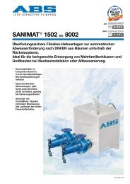
Wiring Diagrams<br />
Three Phase Single Phase<br />
AS <strong>50</strong> <strong>Hz</strong>: AS <strong>50</strong> <strong>Hz</strong>:<br />
S12/2 D, S13/4 D, S17/2 D, S22/4 D,<br />
S26/2 D, S30/2 D,<br />
S10/4 W, M12/2 W<br />
AS <strong>60</strong> <strong>Hz</strong>: AS <strong>60</strong> <strong>Hz</strong>:<br />
S10/4 D, S16/2 D, S13/4 D, S16/4 D,<br />
S17/2 D S18/2 D, , S22/4 D, S25/4 D,<br />
S26/2 D, S30/2 D, S35/2 D<br />
S10/4 W, M12/2 W, S16/2 W, S16/2 W<br />
NOTE:<br />
U1,V1,W1 = Live Di = Seal monitor<br />
PE = Earth F1/FO = Thermal sensor<br />
gr/yel = green/yellow R = Run<br />
blk = black C = Neutral (common)<br />
bl = blue S = Start<br />
br = brown<br />
ATTENTION Explosion-proof pumps may only be used in explosive zones with the<br />
thermal sensors fitted (Leads: FO, F1).<br />
11
AS<br />
5.3.1 Checking direction of rotation<br />
In the case of three phase, when the unit is being commissioned for the first time, <strong>and</strong><br />
also when used on a new site, the direction of rotation must be checked. An incorrect<br />
direction of rotation will reduce the output <strong>and</strong> damage the pump.<br />
The direction of rotation of the pump is checked before final installation by raising it on a<br />
suitable hoist <strong>and</strong> allowing it to run for a short period. The direction of rotation (rotor<br />
rotation) is correct if:<br />
When the pump starts, it makes a jerk in the opposite direction to the arrow on<br />
the side of the pump.<br />
Pump Rotation<br />
When checking the direction of rotation, the submersible pump should be<br />
secured in such a manner that no danger to personnel is caused by the rotating<br />
impeller. Do not place your h<strong>and</strong> near the discharge or suction inlet of the<br />
volute.<br />
If a number of pumps are connected to a single control panel, then each unit must be<br />
individually checked.<br />
5.3.2. Changing direction of rotation<br />
Changing the direction of rotation in the case of pumps not fitted with CEE<br />
round plug with phase change-over facility, should only be carried out by a<br />
qualified person.<br />
If the direction of rotation is incorrect, then this is altered by changing over two phases of<br />
the power supply cable in the control panel.<br />
In the case of submersible pumps with CEE round plug <strong>and</strong> phase change-over facility,<br />
the direction of rotation is altered by swivelling a pair of pins.<br />
12
AS<br />
6. Commissioning<br />
During commissioning the pump/pumping station should be checked <strong>and</strong> a functional test<br />
carried out. Particular attention should be paid to the following:<br />
- Has the electrical connection been carried out in accordance with regulations?<br />
- Have the thermal sensor / sensors been correctly connected?<br />
- Is the seal monitoring device correctly installed?<br />
- Is the current overload correctly set?<br />
- Does the pump sit correctly on the pedestal?<br />
- Is the direction of rotation correct?<br />
- Are the switching On <strong>and</strong> switching Off levels set correctly?<br />
- Are the level control switches functioning correctly?<br />
- Is the gate valve open?<br />
- Does the non-return valve open in the correct direction?<br />
7. MAINTENANCE<br />
Before commencing any maintenance work, the pump should be completely<br />
disconnected from the mains <strong>and</strong> care should be taken that it can not be<br />
inadvertently switched back on.<br />
When carrying out any repair or maintenance work, the safety regulations covering<br />
work in enclosed areas of sewage installations as well as good general technical<br />
practices should be followed<br />
NOTE: The maintenance hints given here have not been designed for "do-it-yourself"<br />
repairs, as special technical knowledge is required to repair these pumps.<br />
A maintenance contract with our works service department will guarantee you the<br />
best technical service under all circumstances.<br />
13
AS<br />
7.1 General maintenance hints<br />
ABS submersible pumps are reliable quality products, each being subjected to careful final<br />
inspection. Lubricated-for-life ball-bearings in combination with our monitoring devices<br />
ensure optimum pump reliability provided that the pump has been connected <strong>and</strong> operated<br />
in accordance with the operating instructions.<br />
Should, nevertheless, a malfunction occur, do not improvise but ask your ABS customer<br />
service for assistance.<br />
This applies particularly if the pump is continually switched off by the current overload in the<br />
control panel or by the alarm.<br />
Regular inspection <strong>and</strong> care is recommended to ensure a long service life.<br />
The ABS service organisation would be pleased to advise you on any applications<br />
you may have <strong>and</strong> to assist you in solving your pumping problems.<br />
NOTE: The ABS warranty conditions are only valid provided that any repair work has<br />
been carried out in ABS approved workshop <strong>and</strong> where original ABS spare<br />
parts have been used.<br />
7.2 Commentary on maintenance of Pump Station <strong>and</strong> Lifting Stations in<br />
accordance with DIN 1986, Part 31.<br />
- It is recommended that the pump station/lifting station be inspected monthly <strong>and</strong> its<br />
function checked.<br />
- In accordance with DIN regulations, the pump station/lifting station should be<br />
maintained by a qualified person at the following intervals:<br />
* in commercial premises - every three months.<br />
* in apartment blocks - every six months.<br />
* in a single family home - once a year.<br />
- In addition we recommended that a maintenance contract be taken out with a<br />
qualified company.<br />
14
AS<br />
7.3 Oil filling <strong>and</strong> Oil changing<br />
The oil chamber between the motor <strong>and</strong> the hydraulic section has been filled at the works<br />
with lubricating oil.<br />
AS Oil Fill Quantity Oil Chamber<br />
AS <strong>50</strong> <strong>Hz</strong> AS <strong>60</strong> <strong>Hz</strong><br />
Pump Type Litres Pump Type Litres<br />
AS <strong>0530</strong> S12/2 0.48 AS <strong>0530</strong> S16/2 0.48<br />
AS <strong>0530</strong> S17/2 0.48 AS <strong>0530</strong> S18/2 0.48<br />
AS <strong>0530</strong> S26/2 0.48 AS <strong>0530</strong> S30/2 0.48<br />
AS <strong>0630</strong> S10/4 0.56 AS <strong>0630</strong> S10/4 0.56<br />
AS <strong>0630</strong> S13/4 0.56 AS <strong>0630</strong> S16/4 0.56<br />
AS <strong>0630</strong> S22/4 0.56 AS <strong>0630</strong> S25/4 0.56<br />
AS <strong>0641</strong> S30/2 0.48 AS <strong>0641</strong> S35/2 0.48<br />
AS <strong>0830</strong> S10/4 0.56 AS <strong>0830</strong> S10/4 0.56<br />
AS <strong>0830</strong> S13/4 0.56 AS <strong>0830</strong> S16/4 0.56<br />
AS <strong>0830</strong> S22/4 0.56 AS <strong>0830</strong> S25/4 0.56<br />
AS <strong>0840</strong> S12/2 0.48 AS <strong>0840</strong> S16/2 0.48<br />
AS <strong>0840</strong> S17/2 0.48 AS <strong>0840</strong> S18/2 0.48<br />
AS <strong>0840</strong> S26/2 0.48 AS <strong>0840</strong> S30/2 0.48<br />
AS <strong>1030</strong> S22/4 0.56 AS <strong>1030</strong> S25/4 0.56<br />
An oil change is only necessary if a fault occurs.<br />
Repair work on explosion-proof submersible pumps may only be carried out by<br />
approved personnel in approved workshops.<br />
When carrying out repairs only original spare parts, supplied by the manufacturer, should<br />
be used.<br />
7.4 Cleaning<br />
If the pump is used for transportable applications then it should be cleaned after each<br />
usage by pumping clear water in order to avoid deposits of dirt <strong>and</strong> encrustation. In the<br />
case of fixed installation, we recommend that the functioning of the automatic level control<br />
system be checked regularly. By switching the selection switch (switch setting “HAND”)<br />
the sump will be emptied. If deposits of dirt are visible on the floats then these should be<br />
cleaned. After cleaning, the pump should be rinsed out with clear water <strong>and</strong> a number of<br />
automatic pumping cycles carried out.<br />
7.5 Venting of the volute<br />
After lowering the pump into a sump full of water, an air lock may occur in the volute <strong>and</strong><br />
cause pumping problems. In this case, raise the pump in the medium <strong>and</strong> then lower it<br />
again. If necessary, repeat this venting procedure.<br />
15
We reserve the right to make alterations in the furtherance of technical development.<br />
<strong>Installation</strong>, Maintenance <strong>and</strong> Service by<br />
ABS Pumps Ltd. . Clonard Road . Wexford , Irel<strong>and</strong> . Telephone ( 053) 63200 . Fax (053) 42335<br />
www.abspumps.com