Safety & Shut-off Blocks - Airline Hydraulics
Safety & Shut-off Blocks - Airline Hydraulics
Safety & Shut-off Blocks - Airline Hydraulics

You also want an ePaper? Increase the reach of your titles
YUMPU automatically turns print PDFs into web optimized ePapers that Google loves.
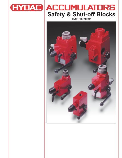
<strong>Safety</strong> & <strong>Shut</strong>-<strong>off</strong> <strong>Blocks</strong><br />
SAB 10/20/32
1. DESCRIPTION<br />
1.1 GENERAL<br />
The safety and shut-<strong>off</strong> block<br />
is designed to protect, shut<strong>off</strong>,<br />
and discharge hydraulic<br />
accumulators or user units.<br />
The compact design simplifies<br />
the hydrualic system<br />
connection and <strong>off</strong>ers the<br />
following advantages.<br />
• minimum space compared<br />
to individual elements<br />
• reduced installation time<br />
• various system connections<br />
• system lockout<br />
It incorporates these features:<br />
1 – pressure release valve<br />
2 – pressure gauge (optional)<br />
3 – shut-<strong>off</strong> valve<br />
4 – manual bleed valve<br />
5 – 2-way solenoid operated<br />
bleed valve (optional)<br />
In accordance with OSHA<br />
requirements for stored<br />
hazardous energy, HYDAC<br />
recommends the use of its<br />
<strong>Safety</strong> and <strong>Shut</strong>-<strong>off</strong> Block<br />
(SAB) with solenoid operated<br />
bleed valve. Use of the<br />
HYDAC SAB block in your<br />
system satisfies OSHA<br />
regulation 29 CFR part 1910<br />
for the accumulator.<br />
Circuit Diagram of a HYDAC SAB Block:<br />
1.2 CONSTRUCTION<br />
The <strong>Safety</strong> and <strong>Shut</strong>-<strong>off</strong> Block<br />
consists of a valve block, a<br />
built-in pressure release valve,<br />
a main shut-<strong>off</strong> valve, and a<br />
manually operated bleed<br />
valve. In addition, an optional<br />
solenoid operated bleed valve<br />
(open when de-energized) (1<br />
allows automatic release of<br />
the accumulator or user unit<br />
and therefore of the hydraulic<br />
system in an emergency or<br />
during shut-down. The<br />
necessary return line<br />
connection is provided in<br />
addition to the gauge<br />
connection.<br />
1.3 CONNECTIONS<br />
The <strong>Safety</strong> and <strong>Shut</strong>-<strong>off</strong> Block<br />
has the following connections:<br />
S – Accumulator Connection<br />
P – System Connection<br />
T – Tank Connection<br />
M1 – Gauge Connection<br />
1.4 TECHNICAL<br />
SPECIFICATIONS<br />
1.4.1 Fluids<br />
Mineral oil, hydraulic oil, water<br />
glycol, non-flammable fluids<br />
(other fluids upon request)<br />
1.4.2 Temperature (for carbon steel)<br />
5º F to 180º F<br />
(-15º C to 80º C)<br />
1.4.3 Maximum Working Pressure<br />
up to 5800 psi (400 bar)<br />
1.5 STANDARD MODELS<br />
1.5.1 Model with manually<br />
operated bleed valve<br />
The basic model code “M”<br />
contains a manually operated<br />
bleed valve for manual<br />
pressure release of the<br />
accumulator.<br />
Sizes: SAB 10 M<br />
SAB 20 M<br />
SAB 32 M<br />
1.5.2 Model with solenoid<br />
operated bleed valve<br />
The “E” model <strong>Safety</strong> and<br />
<strong>Shut</strong>-<strong>off</strong> Block contains a<br />
solenoid operated bleed valve<br />
(open when de-energized) (1 for<br />
automatic pressure release of<br />
the accumulator.<br />
Sizes: SAB 10 E<br />
SAB 20 E<br />
SAB 32 E<br />
1) closed when de-energized on request<br />
2
2. Model Code: SAB <strong>Blocks</strong> SAB 20 E 1 6 Y 1 — 200 C — S 60 L<br />
(also order code)<br />
Designation<br />
<strong>Safety</strong> and <strong>Shut</strong>-<strong>off</strong> Block<br />
Size of main shut-<strong>off</strong> valve<br />
10 = DN 10<br />
20 = DN 20<br />
32 = DN 32<br />
Model<br />
M = Manual discharge<br />
E = Solenoid operated and manual discharge<br />
Block Material<br />
1 = Carbon Steel (standard)<br />
3 = Stainless Steel (316)<br />
7 = Others<br />
Seal Material<br />
2 = NBR (BUNA N)<br />
4 = IIR (Butyl)<br />
6 = FPM (Viton) (standard)<br />
7 = Others<br />
2-Way Solenoid Operated Bleed Valve<br />
Operating Function<br />
Y = Normally Open (standard)<br />
Z = Normally Closed<br />
Solenoid<br />
1 = 24 VDC (standard)<br />
2 = 110 VAC – 60 Hz (standard)<br />
3 = 220 VAC – 50 Hz<br />
4 = 220 VAC – 60 Hz<br />
7 = Others<br />
Pressure Relief Valve - Pressure Range<br />
200 = up to 2900 PSI<br />
315 = up to 4600 PSI<br />
400 = up to 5800 PSI<br />
(others upon request)<br />
Connection Type<br />
Threaded:<br />
C = SAE (ANSI B 1.1) (BSP system connections (“P”) available, all other connection threads remain SAE)<br />
Flanged (SAB 32 only):<br />
E = SAE 2” – 3000 psi (Code 61)<br />
F = SAE 1-1/2” – 6000 psi (Code 62)<br />
Adapter (required only for safety and shut-<strong>off</strong> blocks with threaded connection)<br />
SAE: S 60 = 1 1/16”-12UN BSP: S 10 = G3/4”<br />
S 62 = 1 5/8”-12UN S 11 = G1”<br />
S 63 = 1 7/8”-12UN S 12 = G1 1/4”<br />
S 64 = 3/4”-16UNF S 13 = G2”<br />
S 620 = 1 5/8”-12UN S 309 = G2”<br />
S 630 = 1 7/8”-12UN<br />
(see section 4 - others upon request)<br />
Locking Device (if required)<br />
L<br />
(Not all combinations are available)<br />
3
3. DIMENSIONS<br />
3.1 TYPE SAB 10 M/E...C<br />
with direct operating pressure relief valve size 6 (Max. working pressure 5800 psi)<br />
Type<br />
Approximate Weight<br />
kg (lbs.)<br />
SAB 10 M 3.6 (8.0)<br />
SAB 10 E 4.0 (8.8)<br />
Dimensions in inches<br />
Note: for “M” Type block the 2-way<br />
directional valve is replaced with a plug<br />
Operating Pressure in bar<br />
450<br />
400<br />
300<br />
200<br />
100<br />
50<br />
Operating Pressure in psi<br />
Direct Operating<br />
Pressure Relief Valve<br />
Size 6<br />
6500<br />
6000<br />
400<br />
5000<br />
315<br />
4000<br />
3000<br />
2000<br />
1000<br />
500<br />
200<br />
100<br />
50<br />
25<br />
3 6 9 12 15<br />
Flow in gpm<br />
lowest<br />
adjustable<br />
pressure<br />
4<br />
10 20 30 40 50 60<br />
Flow in l/min
3.2 TYPE SAB 20 M/E...C<br />
with direct operating pressure relief valve size 10 (Max. working pressure 5800 psi)<br />
Type<br />
Approximate Weight<br />
kg (lbs.)<br />
SAB 20 M 6.8 (15.0)<br />
SAB 20 E 7.2 (15.8)<br />
Dimensions in inches<br />
Note: for “M” Type block the 2-way<br />
directional valve is replaced with a plug<br />
Operating Pressure in bar<br />
600<br />
500<br />
400<br />
300<br />
200<br />
100<br />
50<br />
Operating Pressure in psi<br />
9000<br />
8000<br />
7000<br />
6000<br />
5000<br />
4000<br />
3000<br />
2000<br />
1000<br />
Direct Operating<br />
Pressure Relief Valve<br />
Size 10<br />
630<br />
400<br />
315<br />
200<br />
100<br />
50<br />
5 10 15 20 25 30<br />
Flow in gpm<br />
lowest<br />
adjustable<br />
pressure<br />
20 40 60 80 100 120<br />
Flow in l/min<br />
5
3.3 TYPE SAB 32 M/E...C<br />
with direct operating pressure relief valve size 10 (Max. working pressure 5800 psi)<br />
Type<br />
Approximate Weight<br />
kg (lbs.)<br />
SAB 32 M 12.0 (26.4)<br />
SAB 32 E 12.4 (27.2)<br />
Dimensions in inches<br />
Note: for “M” Type block the 2-way<br />
directional valve is replaced with a plug<br />
Operating Pressure in bar<br />
600<br />
500<br />
400<br />
300<br />
200<br />
100<br />
50<br />
Operating Pressure in psi<br />
9000<br />
8000<br />
7000<br />
6000<br />
5000<br />
4000<br />
3000<br />
2000<br />
1000<br />
Direct Operating<br />
Pressure Relief Valve<br />
Size 10<br />
630<br />
400<br />
315<br />
200<br />
100<br />
50<br />
5 10 15 20 25 30<br />
Flow in gpm<br />
lowest<br />
adjustable<br />
pressure<br />
6<br />
20 40 60 80 100 120<br />
Flow in l/min
3.4 TYPE SAB 32 M/E...E<br />
with direct operating pressure relief valve size 10 (Max. working pressure 3000 psi)<br />
*Hexagonal socket head cap screws<br />
M 12x35-DIN 912 (Part HYDAC No. 00602100<br />
have to be ordered separately<br />
Type<br />
Approximate Weight<br />
kg (lbs.)<br />
SAB 32 M 13.6 (30.0)<br />
SAB 32 E 14.0 (30.8)<br />
Dimensions in inches<br />
Note: for “M” Type block the 2-way<br />
directional valve is replaced with a plug<br />
Operating Pressure in bar<br />
600<br />
500<br />
400<br />
300<br />
200<br />
100<br />
50<br />
Operating Pressure in psi<br />
9000<br />
8000<br />
7000<br />
6000<br />
5000<br />
4000<br />
3000<br />
2000<br />
1000<br />
Direct Operating<br />
Pressure Relief Valve<br />
Size 10<br />
630<br />
400<br />
315<br />
200<br />
100<br />
50<br />
5 10 15 20 25 30<br />
Flow in gpm<br />
lowest<br />
adjustable<br />
pressure<br />
20 40 60 80 100 120<br />
Flow in l/min<br />
7
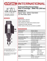
3.5 Type SAB 32 M/E...F<br />
with direct operating pressure relief valve size 10 (Max. working pressure 5800 psi)<br />
*Hexagonal socket head cap screws<br />
M 16x55-DIN 912 (Part HYDAC No. 00601496<br />
have to be ordered separately<br />
Type<br />
Approximate Weight<br />
kg (lbs.)<br />
SAB 32 M 13.6 (30.0)<br />
SAB 32 E 14.0 (30.8)<br />
500 7000<br />
400<br />
6000<br />
400<br />
5000<br />
315<br />
300 4000<br />
200 3000<br />
200<br />
2000<br />
100<br />
100<br />
Dimensions in inches<br />
50<br />
1000<br />
50<br />
Note: for “M” Type block the 2-way<br />
directional valve is replaced with a plug 5 10 15 20 25 30<br />
Flow in gpm<br />
Operating Pressure in bar<br />
600<br />
Operating Pressure in psi<br />
Direct Operating<br />
Pressure Relief Valve<br />
Size 10<br />
9000<br />
630<br />
8000<br />
lowest<br />
adjustable<br />
pressure<br />
8<br />
20 40 60 80 100 120<br />
Flow in l/min
4. ADAPTERS<br />
Thread<br />
O-ring<br />
Thread<br />
O-ring<br />
O-ring<br />
O-ring<br />
Figure 1<br />
Figure 2<br />
Type SAB Accumulator Type Adapter Fig. Thread A B C D E F<br />
SAB 10/20 SB330-Size 1 / SBO-Size 2 to 3.5 S 60 1 1 1/16-12 UN 1.26 1.60 2.17 0.55 0.75 0.60<br />
SB330-Size 4 to 6 / SB600-Size 1 to 4 S 62 1 1 5/8-12 UN 1.90 2.60 2.24 0.90 0.75 0.60<br />
SB330/600-Size 10 to 54 S 63 1 1 7/8-12 UN 2.13 2.60 2.24 0.90 0.75 0.60<br />
SBO-Size 0.32 to 1.4 S 64 1 3/4-16 UNF 0.90 1.60 2.00 0.40 0.60 0.45<br />
SAB 32 SB330-Size 4 to 6 / SB600-Size 1 to 4 S 620 2 1 5/8-12 UN 1.89 3.94 1.93 0.87 0.75 0.60<br />
SB330/600-Size 10 to 54 S 630 2 1 7/8-12 UN 2.13 3.94 1.93 1.18 0.75 0.60<br />
5. FLOW RATE GRAPH<br />
30<br />
Pressure Drop vs. Flow Rate<br />
∆P (psi)<br />
20<br />
SAB10<br />
SAB20<br />
SAB32<br />
10<br />
0<br />
50 100 150 200 250 300<br />
Q (gpm)<br />
9
6. SPARE PARTS<br />
(SAB 32 only)<br />
10
SAB Block SAB 10M SAB 20M SAB 32M<br />
SAB 10E SAB 20E SAB 32E<br />
Description Item Dimensions<br />
Repair Kit Part No. Part No. Part No.<br />
02104500 (NBR) 02104502 (NBR) 02104504 (NBR)<br />
02104501 (FPM) 02104503 (FPM) 02104505 (FPM)<br />
Spindle 1<br />
Disc 2<br />
O-ring 3 10 x 2 15 x 2.5 20 x 3<br />
Ball 4<br />
Lever 5<br />
Spindle 6<br />
O-ring 7 6 x 2<br />
Set Screw 8<br />
Orifice 9<br />
Support Ring 10.1<br />
O-ring 10.2<br />
O-ring 10.3<br />
Sealing Cup 11<br />
O-ring 12 21 x 2 34 x 2.5 53 x 2.5<br />
Usit-ring 13 17.4 x 24 x 1.5 24.7 x 31.5 x 2 24.7 x 31.5 x 2<br />
O-ring 14 19 x 3 26 x 3 26 x 3<br />
Support Ring 15 20.3 x 25 x 1 27.3 x 32 x 1 27.3 x 32 x 1<br />
O-ring 16 29.7 x 2.8 29.7 x 2.8 37.2 x 3<br />
Plug 17 7/16-20UNF 3/4-16UNF 3/4-16UNF<br />
18 N/A N/A G1/8<br />
Manual Bleed Valve Part No. Part No. Part No.<br />
Repair Kit 02115648 (NBR) 02115648 (NBR) 02115648 (NBR)<br />
02115649 (Viton) 02115649 (Viton) 02115649 (Viton)<br />
Spindle, handle, ball 6<br />
O-ring 7 Dimensions See Above<br />
Set Screw 8<br />
2-way solenoid operated Part No. Part No. Part No.<br />
bleed valve (only for SAB...E) 00710953 00710953 00710953<br />
Bleed Valve 10<br />
Support Ring 10.1<br />
O-ring 10.2<br />
O-ring 10.3<br />
Seal Kit Part No. Part No. Part No.<br />
02100277 (NBR) 02100279 (NBR) 02100281 (NBR)<br />
02100278 (FPM) 02100280 (FPM) 02100282 (FPM)<br />
O-ring 3<br />
O-ring 7<br />
Set Screw 8<br />
Orifice 9<br />
Support Ring 10.1<br />
O-ring 10.2<br />
O-ring 10.3 Dimensions See Above<br />
Sealing Cup 11<br />
O-ring 12<br />
Usit-ring 13<br />
O-ring 14<br />
Support Ring 15<br />
O-ring 16<br />
Plug 17<br />
18<br />
O-ring dimensions are in mm<br />
11
Other Products from HYDAC’s Accumulator Line<br />
Bladder Accumulators<br />
The bladder style accumulator is a great general purpose accumulator. It has<br />
a wide range of sizes for energy storage requirements and is well suited for<br />
shock applications.<br />
Nominal volume: 1 qt. to 15 gal.<br />
Max. working pressure: 3000, 5000 and up to 15000 psi<br />
Flow rate: up to 480 gpm<br />
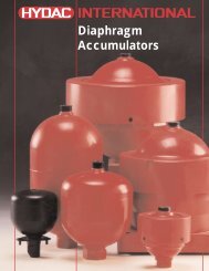
Diaphragm Accumulators<br />
Diaphragm accumulators are frequently used where small volumes are<br />
required, light weight is important, a higher pressure ratio is required (up to<br />
10:1), and low cost is a prime factor. Two styles are available weld (nonrepairable)<br />
and threaded (repairable). Both are suited for energy storage and<br />
shock applications.<br />
Nominal volume: 5 in 3 to 1 gal.<br />
Max. working pressure: 3000, 4700, and up to 10,000 psi<br />
Flow rate: up to 40 gpm<br />
Piston Accumulators<br />
A wide range of piston accumulators is available. Piston position monitoring is<br />
available using proximity switches, extending piston rod or ultrasonic<br />
techniques. Auxiliary gas bottles are frequently used with piston accumulators<br />
to provide the required gas volume.<br />
Nominal volume: 1 qt. to 100 gal.<br />
Max. working pressure: 3000, 5000, and up to 15000 psi<br />
Flow Rate: up to 2000 gpm<br />
Request catalog # 02071832<br />
Request catalog # 02071831<br />
Request catalog # 02068597<br />
Charging & Gauging<br />
To maintain system performance, HYDAC recommends a regular check of the<br />
gas precharge pressure. A loss in the gas precharge pressure will cause a<br />
drop in the system efficiency and could cause damage to the bladder,<br />
diaphragm or piston accumulator. By means of a charging and gauging unit,<br />
hydro-pneumatics accumulators are precharged with dry nitrogen or their<br />
existing gas precharge pressure is checked. For these purposes, a charging<br />
and gauging unit is connected to a commercially available nitrogen bottle via<br />
a flexible hose. The charging and gauging units incorporate a gauge, check<br />
valve in the charging connection, manual bleed valve and T-handle.<br />
Request catalog # 02071833<br />
© Copyright 1999 HYDAC TECHNOLOGY CORPORATION - Brochure - SAB <strong>Safety</strong> & <strong>Shut</strong>-<strong>off</strong> <strong>Blocks</strong> - #02071830 / 08.00<br />
HYDAC CORPORATION<br />
2280 City Line Road • Bethlehem, PA 18017<br />
Phone (610) 264-9503 • Fax (610) 264-7529<br />
www.hydacusa.com • powerup@hydacusa.com