ETS 1700.qx - Airline Hydraulics
ETS 1700.qx - Airline Hydraulics
ETS 1700.qx - Airline Hydraulics

Create successful ePaper yourself
Turn your PDF publications into a flip-book with our unique Google optimized e-Paper software.
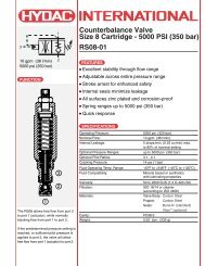
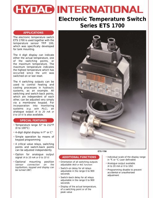
Electronic Temperature Switch<br />
Series <strong>ETS</strong> 1700<br />
APPLICATIONS<br />
The electronic temperature switch<br />
<strong>ETS</strong> 1700 is used together with the<br />
temperature sensor TFP 100,<br />
which was specifically developed<br />
for tank mounting.<br />
The 4 digit display can indicate<br />
either the actual temperature, one<br />
of the switching points, or<br />
the maximum temperature. The<br />
maximum temperature indicates<br />
the highest temperature which has<br />
occurred since the unit was<br />
switched on or last reset.<br />
The 4 switching outputs can be<br />
used to control heating and<br />
cooling processes in hydraulic<br />
systems, as an example. All<br />
switching and switch-back points,<br />
which are independent of each<br />
other, can be adjusted very simply<br />
via a membrane keypad. For<br />
incorporation into monitoring<br />
systems (e.g. with PLC), an<br />
analogue output (4 to 20 mA or<br />
0 to 10 V) is also available.<br />
SPECIAL FEATURES<br />
• Temperature range 32° to 212°F<br />
(0 to 100°C)<br />
• 4-digit digital display in F° or C°<br />
• Simple operation by means of<br />
keypad programming<br />
• 4 critical value relays, switching<br />
points and switch-back points<br />
can be adjusted independently<br />
• Option for analogue output<br />
signal (4 to 10 mA or 0 to 10 V)<br />
• Optional mounting position<br />
(sensor connection on the<br />
top/bottom, keypad and display can<br />
be turned 180˚)<br />
ADDITIONAL FUNCTIONS<br />
• Orientation of all switching outputs<br />
adjustable (N/O or N/C function)<br />
• Switch-on delay for all relays<br />
adjustable in the range 0 to 900<br />
seconds<br />
• Switch-back delay for all relays<br />
adjustable in the range 0 to 900<br />
seconds<br />
• Display of the actual temperature,<br />
of a switching point or of the<br />
peak value<br />
<strong>ETS</strong> 1700<br />
• Individual scale of the display range<br />
in °F, or °C (user definable)<br />
• Analogue output available<br />
(4 to 20 mA or 0 to 10V)<br />
• Programming disable to prevent<br />
accidental or unauthorized<br />
adjustment
Setting Options:<br />
Setting ranges of the switching points<br />
and/or switch-back hysteresis:<br />
• Switching point relays 1 to 4:<br />
• Switch-back point relays 1 to 4:<br />
1.5 % .. 100 % FS<br />
1 % .. 99 % FS<br />
or alternatively<br />
1 % .. 99 % FS<br />
switch-back hysteresis 1 to 4:<br />
Note: FS (Full Scale) = relative to the full measuring range<br />
Pin Connections:<br />
Relay outputs, analogue output, supply voltage<br />
Relay 4<br />
= Switching Point 4<br />
Relay 3<br />
= Switching Point 3<br />
14<br />
13<br />
12<br />
11<br />
10<br />
9<br />
Switching point /switch-back point:<br />
The switching point is defined as being the temperature<br />
value, which when reached (when on the temperature rise),<br />
causes a change in the switching direction or orientation.<br />
This output state is maintained until the temperature falls<br />
below the switch-back point allocated to the switching<br />
point. The switch-back point is determined by the adjusted<br />
hysteresis value.<br />
Relay 2<br />
= Switching Point 2<br />
Relay 1<br />
= Switching Point 1<br />
Analogue Output (0 V)<br />
8<br />
7<br />
6<br />
5<br />
4<br />
Ground<br />
Switching point - Hysteresis = Switch-back point<br />
Analogue Output (signal +)<br />
3<br />
Supply (0 V)<br />
2<br />
Temperature<br />
SP<br />
RSP<br />
ON<br />
OFF<br />
HY<br />
SP<br />
RSP<br />
Supply (+ input voltage)<br />
Sensor Connections:<br />
Interval view of pin connections<br />
(on the <strong>ETS</strong> 1700)<br />
5-pole Binder connector,<br />
series 723<br />
1<br />
SP<br />
HY<br />
RSP<br />
Assembly:<br />
Time<br />
= Switching Point<br />
= Hysteresis<br />
= Switch-back Point<br />
(SP-HY)<br />
When used in critical applications (e.g. strong vibrations or<br />
knocks) the <strong>ETS</strong> 1700 must be mounted on rubber buffers<br />
(DIN vibration mounts). When supplied, the sensor connection<br />
is accessible from the bottom and the electrical connection<br />
is accessible from the top. Depending on the application,<br />
the front panel of the instrument can be turned 180˚ so that<br />
the electrical connection can be made from underneath and<br />
the sensor connection can be made from the top.<br />
4<br />
5<br />
3<br />
2<br />
1<br />
Pin 1 = + supply<br />
Pin 2 = + signal<br />
Pin 3 = reserved<br />
Pin 4 = - signal<br />
Pin 5 = - supply<br />
= plug housing<br />
for screen<br />
Internal view of pin connections<br />
(on the TFP 100)<br />
4-pole Binder connector,<br />
series 714<br />
2 3<br />
1 2 3 4 5<br />
1 2 3 4<br />
sensor<br />
resistance<br />
<strong>ETS</strong> 1700<br />
5 pole Binder<br />
connector<br />
series 723<br />
4 pole Binder<br />
connector<br />
series 714<br />
TFP 100<br />
1<br />
4<br />
2<br />
Pin 1 = + supply<br />
Pin 2 = + signal<br />
Pin 3 = - signal<br />
Pin 4 = - supply
Model Code: <strong>ETS</strong> 1700<br />
Type of Sensor<br />
<strong>ETS</strong> 1700 = for PT 100 sensor<br />
(Temperature sensor FTP 100 must be ordered separately)<br />
Display (temperature unit on faceplate)<br />
01 = 4 digit °C<br />
02 = 4 digit °F<br />
Measuring Range<br />
100 = 32° to 212°F (0° to 100°C)<br />
Modification Number<br />
000 = standard (determined by manufacturer)<br />
<strong>ETS</strong> 170 01 - 100 - 000 .<br />
Technical Data: <strong>ETS</strong> 1700 Electronic Temperature Switch<br />
Measuring Range<br />
Accuracy (display, analogue output)<br />
32° to 212°F (0° to 100°C)<br />
≤ ± 1.0% of the measuring range<br />
Repeatability<br />
≤ ± 0.25% of the measuring range<br />
Temperature Drift in the zero point: ≤ ± 0.054%/°F (≤ ± 0.03%/°C)<br />
ambient temperature range range: ≤ ± 0.054%/°F (≤ ± 0.03%/°C)<br />
Output Signal<br />
4 to 20 mA, ohmic resistance ≤ 400 Ω<br />
0 to 10 V, ohmic resistance ≤ 2 Ω<br />
Switching Output Type<br />
Switching Voltage<br />
Switching Current<br />
Switching Capacity<br />
Life Expectancy of Contacts<br />
Reaction Time (without switching delay)<br />
Switching Point Setting Range<br />
Setting Range of Hysteresis /<br />
Switch-back Points<br />
Ambient Temperature Range<br />
Storage Temperature Range<br />
4 relays with change-over contacts in 2 groups<br />
(common supply of each group connected)<br />
0.1 to 250 VAC / VDC<br />
0.009 to 2 A<br />
400 VA, 50 W<br />
(for inductive load use varistors)<br />
≥ 20 million (minimum load)<br />
≥ 1 million (maximum load)<br />
approx. 20 ms<br />
1.5 to 100% FS<br />
1 to 99% FS<br />
-13 to 140 ˚F (-25 to 60 ˚C)<br />
-40 to 176 ˚F (-40 to 80 ˚C)<br />
mark EN 50081-1 and -2, EN 50082-1 and -2<br />
Vibration Resistance<br />
Shock Resistance<br />
approx. 5 g<br />
approx. 10 g<br />
Sensor Connection 5 pole Binder connector, series 681<br />
Electrical Connection<br />
14 pole terminal strip<br />
(cross-section of connection max. 1.5 mm 2 )<br />
Supply Voltage 22 to 32 VDC (residual ripple ≤ 10%)<br />
Current Consumption<br />
Display<br />
approx. 200 mA<br />
4-digit, 7-segment LED, red (digits 13mm high)<br />
Safety Type IP 65<br />
Weight<br />
approx. 800 g<br />
3
Drawing and Dimensions: <strong>ETS</strong> 1700<br />
4.96"<br />
126mm<br />
4.49"<br />
114mm<br />
PG 11 Cable gland<br />
(2 places)<br />
5.9"<br />
150mm<br />
3.76" 3.3"<br />
95.5mm 84mm<br />
countersunk<br />
to DIN 74-Km5<br />
(4 places)<br />
mode<br />
ON<br />
OFF<br />
SP1<br />
ON<br />
OFF<br />
SP2<br />
1.46"<br />
37mm<br />
connection line LIYCY<br />
(3m long)<br />
reset<br />
max<br />
ON<br />
OFF<br />
SP3<br />
;;;<br />
;;;<br />
;;;<br />
Dimensions are for general information only. Please<br />
verify all critical dimensions by requesting a certified print.<br />
Included Accessories:<br />
• PG 11 Cable Glands<br />
• 4 Mounting Screws (M5 x 20mm)<br />
• 5-pole Binder connector, series 681<br />
• 3m connection line for TFP 100<br />
(LIYCY 4x0.25 mm 2 )<br />
Other Accessories:<br />
(must be ordered separately)<br />
Temperature Sensor TFP 100 (part no. 00904696)<br />
• ZBE 03 plug included<br />
Safety Sleeve<br />
(for tank mounting part no. 00906170)<br />
Mounting Kit <strong>ETS</strong> 1700<br />
• 4 Vibration Mounts<br />
• 4 Screws (M5 x 6mm)<br />
max<br />
ON<br />
OFF<br />
°C<br />
SP4<br />
<strong>ETS</strong>1700<br />
+<br />
-<br />
5 pole Binder<br />
Series 681<br />
TFP 100 (temp. sensor)<br />
ZBE 03 plug<br />
Safety Sleeve<br />
hex SW27<br />
0.73"<br />
18.5mm<br />
Please contact HYDAC for details on all of the accessories above<br />
0.12"<br />
3mm<br />
0.65"<br />
14mm<br />
G 1/2<br />
connection port<br />
centerline<br />
3.15"<br />
80mm<br />
4.96"<br />
126mm<br />
0.65"<br />
16.5mm<br />
0.55"<br />
14mm<br />
ø 1.06"<br />
27mm<br />
1.02"<br />
26mm<br />
3.94"<br />
100mm<br />
1.5"<br />
38.5mm<br />
ø 0.76"<br />
19.3mm<br />
ø 0.24"<br />
6mm<br />
ø 0.33"<br />
8mm<br />
© Copyright 2000 HYDAC TECHNOLOGY CORPORATION - Brochure - Electronic Temperature Sensor Series <strong>ETS</strong> 1700 #02071826 / 03/00<br />
HYDAC TECHNOLOGY CORPORATION<br />
Electronic Division<br />
2260 City Line Road • Bethlehem, PA 18017<br />
Phone (610) 266-0100 • Fax (610) 264-7529<br />
www.hydacusa.com • powerup@hydacusa.com