Diaphragm Accumulators - Airline Hydraulics
Diaphragm Accumulators - Airline Hydraulics
Diaphragm Accumulators - Airline Hydraulics
You also want an ePaper? Increase the reach of your titles
YUMPU automatically turns print PDFs into web optimized ePapers that Google loves.
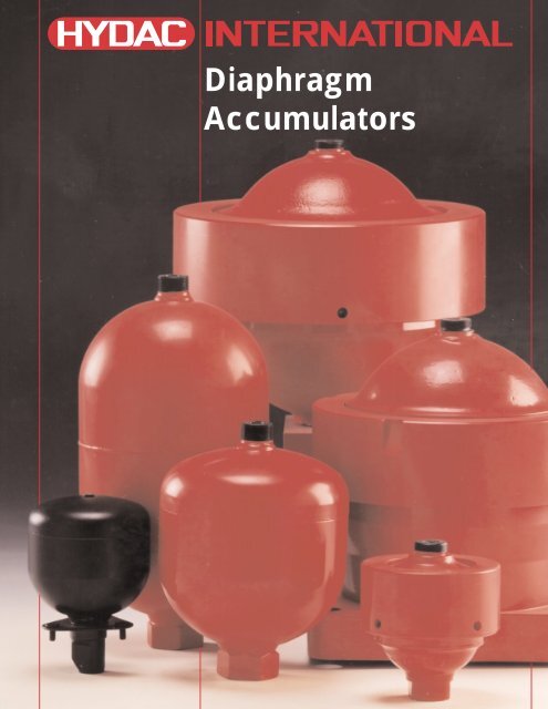
<strong>Diaphragm</strong><br />
<strong>Accumulators</strong>
HYDAC<br />
<strong>Diaphragm</strong><br />
<strong>Accumulators</strong><br />
Index<br />
Page<br />
1. Description 3<br />
Introduction 3<br />
Construction 3<br />
2. Applications 4<br />
3. Technical Data 6<br />
Operation 6<br />
Technical Specifications 6<br />
Temperature Effect 6<br />
Formulas for Sizing <strong>Accumulators</strong> 7<br />
Sizing Example 7<br />
4. Installation Requirements 8<br />
5. Model Code 9<br />
6. Welded Type (non-repairable) Specifications 10<br />
7. Threaded Type (repairable) Specifications 11<br />
2
1. DESCRIPTION<br />
INTRODUCTION<br />
HYDAC diaphragm accumulators<br />
utilize the compressibility of a gas<br />
(nitrogen) in storing hydraulic energy.<br />
The gas is required because fluids<br />
are practically incompressible and<br />
thus, can not store energy by<br />
themselves. The diaphragm is<br />
utilized to separate the gas and the<br />
fluid sides of the accumulator<br />
The diaphragm accumulator<br />
functions by drawing in fluid from<br />
the hydraulic circuit when the<br />
pressure increases and thus,<br />
compresses the gas. It returns this<br />
energy to the circuit as the pressure<br />
decreases by the expansion of the<br />
gas.<br />
A poppet is incorporated into the<br />
diaphragm to prevent its extrusion<br />
through the fluid port.<br />
HYDAC manufactures two types of<br />
diaphragm accumulators:<br />
• welded (non-repairable)<br />
• threaded (repairable)<br />
These have been successfully<br />
applied to both industrial and<br />
mobile applications in energy<br />
storage, maintaining pressure,<br />
leakage compensation, and vehicle<br />
hydraulic systems (e.g. brake and<br />
suspension).<br />
CONSTRUCTION<br />
Welded Type<br />
gas valve<br />
accumulator<br />
shell<br />
diaphragm<br />
poppet<br />
fluid port<br />
It consists of:<br />
• an electronic beam welded shell<br />
with gas charging valve or<br />
alternately, completely sealed.<br />
Fluid ports are available in<br />
various thread configurations.<br />
• a flexible diaphragm to separate<br />
the gas and fluid sides.<br />
• a poppet.<br />
Threaded Type<br />
gas valve<br />
accumulator<br />
shell<br />
locking ring<br />
diaphragm<br />
poppet<br />
fluid port<br />
It consists of:<br />
• a forged upper section with the<br />
gas valve.<br />
• a forged lower section with the<br />
fluid port.<br />
• a locking ring to fasten the upper<br />
and lower sections together.<br />
• a replaceable, flexible diaphragm<br />
to separate the gas and<br />
fluid sides.<br />
• a poppet<br />
<strong>Diaphragm</strong> Materials<br />
Not all fluids are compatible with<br />
every elastomer at all temperatures.<br />
Therefore, HYDAC offers the<br />
following choice of elastomers:<br />
• NBR (Standard Nitrile)<br />
• LT-NBR (Low Temperature Nitrile)<br />
• ECO (Epichlorohydrin)<br />
• IIR (Butyl)<br />
• FPM (Fluorelastomer)<br />
• others available upon request.<br />
Corrosion Protection<br />
HYDAC offers internal and/or<br />
external protective coatings. If this is<br />
insufficient, stainless steel is also<br />
available.<br />
Mounting Position<br />
<strong>Diaphragm</strong> accumulators by design<br />
may be mounted in any position. In<br />
systems where contamination is a<br />
problem, we recommend a vertical<br />
mount with fluid port oriented<br />
downward.<br />
System Mounting<br />
HYDAC diaphragm accumulators<br />
are designed to be screwed directly<br />
onto the system. We also<br />
recommend the use of our mounting<br />
components, refer to Mounting<br />
Components brochure # A 3.502, to<br />
minimize risk of failure due to system<br />
vibrations.<br />
3
2. APPLICATIONS<br />
HYDAC diaphragm accumulators<br />
have been applied successfully in<br />
the following industries:<br />
• Agriculture<br />
• Forestry<br />
• Machine Tools<br />
• Mining<br />
• Mobile Equipment<br />
• Off Road Equipment<br />
Some examples are shown here<br />
and on the next page.<br />
HYDAC welcomes the opportunity<br />
to work with you on your<br />
application.<br />
A diaphragm accumulator is used to<br />
support peak demand and for<br />
emergency supply in the event of a<br />
pump failure<br />
With hydraulic suspensions,<br />
diaphragm accumulators are used<br />
to absorb shock.<br />
<strong>Diaphragm</strong> accumulators can<br />
enhance motion control and<br />
dampen vibration.<br />
4
This picture shows two energy<br />
storage applications on fatigue<br />
testing equipment.<br />
These pictures show a heavy duty<br />
shock application.<br />
5
3. TECHNICAL DATA<br />
OPERATION<br />
Describing the operation of<br />
diaphragm accumulators:<br />
1 The diaphragm is precharged<br />
with nitrogen. This causes the<br />
poppet to close, preventing the<br />
diaphragm from extruding out of<br />
the fluid port.<br />
2 Accumulator at maximum<br />
working pressure. The difference<br />
in volume (∆V) between the<br />
maximum and the minimum<br />
working pressure corresponds to<br />
the effective fluid volume:<br />
3 When the minimum working<br />
pressure is reached, a small<br />
amount of fluid should remain in<br />
the accumulator. This is to<br />
prevent the poppet from<br />
impacting the base on each<br />
cycle. Thus, p 0 should always be<br />
lower than p 1 .<br />
∆V = V1 - V2<br />
TECHNICAL<br />
SPECIFICATION<br />
Maximum Working Pressure<br />
Please refer to tables on pages 10<br />
and 11.<br />
In other countries maximum working<br />
pressure may be different.<br />
Maximum Allowable Pressure Ratio<br />
Ratio of max. working pressure (p 2 )<br />
to gas precharge pressure ( p 0 ).<br />
• welded type:<br />
size 0.075 to 2 8 : 1<br />
size 2.8 and 3.5 4 : 1<br />
• threaded type<br />
all sizes 10 : 1<br />
Nominal Volume (size)<br />
Please refer to tables on pages 10<br />
and 11.<br />
Effective Gas Volume (V 0 )<br />
Corresponds to the gas volume.<br />
Recommended Gas Precharge<br />
Pressure<br />
• for energy storage:<br />
p 0 = 0.9 x p 1<br />
p 1 = minimum working pressure<br />
• for shock absorption:<br />
p 0 = (0.6 to 0.9) x p m<br />
p m = median working pressure at<br />
free flow<br />
• for pulsation dampening:<br />
p 0 = (0.6 to 0.8) x p m<br />
p m = median working pressure<br />
TEMPERATURE EFFECT<br />
To ensure that the recommended<br />
precharged pressure is maintained,<br />
even at relatively low or high<br />
operating temperatures, the gas<br />
precharge pressure should be<br />
adjusted for temperature. The<br />
formulas below relate the precharge<br />
temperature (T 0 ) to the operating<br />
temperature (T). Please refer to the<br />
sizing example on page 7.<br />
P0<br />
V0<br />
P2<br />
V2<br />
P1<br />
V1<br />
∆V<br />
Effective Fluid Volume<br />
Volume of fluid available between<br />
the working pressure p 2 and p 1 .<br />
Fahrenheit<br />
p 0,T0 = p 0,T2 x (<br />
T0 + 460 ) T2 + 460<br />
1 2 3<br />
p 0 = gas precharge pressure<br />
p 1 = minimum working pressure<br />
p 2 = maximum working pressure<br />
V 0 = effective gas volume of<br />
the accumulator<br />
V 1 = gas volume at p 1<br />
Fluids<br />
Mineral oil, hydraulic oil, water,<br />
water-glycol, and water emulsions.<br />
For other fluids, please consult<br />
HYDAC.<br />
Operating Temperature<br />
Selection of the shell material and<br />
elastomer depends on the operating<br />
temperature range of the unit. For<br />
selection, please refer to pages 8<br />
and 9.<br />
T 0 = precharge temperature in °F<br />
T 2<br />
= maximum operating<br />
temperature in °F<br />
p 0 ,T 0 = gas precharge pressure at<br />
precharge temperature<br />
p 0 ,T 2 = gas precharge pressure at<br />
maximum operating<br />
pressure<br />
Celsius<br />
p 0,T0 = p 0,T2 x (<br />
T0 + 273 ) T2 + 273<br />
V 2 = gas volume at p 2<br />
T 0 = temperature at precharging<br />
T 1 = minimum operating temperature<br />
T 2 = maximum operating temperature<br />
Flow Rate<br />
The maximum allowable flow rate<br />
depends on the accumulator size.<br />
For selection, please refer to pages<br />
10 and 11.<br />
T 0 = precharge temperature in °C<br />
T 2<br />
= maximum operating<br />
temperature in °C<br />
p 0 ,T 0 = gas precharge pressure at<br />
precharge temperature<br />
6<br />
p 0 ,T 2 = gas precharge pressure at<br />
maximum operating<br />
temperature
FORMULAS FOR SIZING<br />
ACCUMULATORS<br />
The compression and expansion<br />
processes taking place in<br />
hydropneumatic accumulator are<br />
governed by the general gas laws.<br />
The following applies for ideal gases:<br />
p 0 x V n 0 = p 1 x V n 1 = p 2 x V n 2 ,<br />
where the time related change of<br />
state is represented by the polytropic<br />
exponent “n”. For slow expansion<br />
and compression processes which<br />
occur almost isothermically, the<br />
polytropic exponent can be set at<br />
n=1. For rapid processes, the<br />
diabetic change of state can be<br />
calculated using n = k = 1.4 (for<br />
nitrogen as a diatomic gas) (1 .<br />
For pressures above 3000 psi the real<br />
gas behavior deviates considerably<br />
from the ideal one, which reduces the<br />
effective fluid volume ∆V. In such<br />
cases a correction is made which<br />
takes into account a change in the<br />
adiabatic exponent (k).<br />
By using the following formulas, the<br />
required gas volume V 0 can be<br />
calculated for various calculations.<br />
Pressures of up to 150 psi must<br />
always be used as absolute<br />
pressures in the formulas.<br />
Calculation Formulas ∆V<br />
V0<br />
polytropic:<br />
=<br />
isothermal:<br />
(n=1)<br />
adiabatic:<br />
(n = k = 1.4)<br />
V0 =<br />
P0<br />
P1<br />
V0 =<br />
( ) ( )<br />
P0<br />
P1<br />
∆V<br />
( ) ( )<br />
1/n 1/n<br />
P0<br />
P2<br />
P0<br />
P2<br />
∆V<br />
( ) ( )<br />
P0<br />
P1<br />
0.714<br />
P0<br />
0.714<br />
P2<br />
Correction factors to take into<br />
account the real gas behavior (2<br />
V 0,real = C i x V 0,ideal or<br />
∆V real = ∆ V ideal<br />
C i<br />
for adiabatic change of condition:<br />
V 0,real = C a x V 0,ideal or<br />
∆V real = ∆ V ideal<br />
C a<br />
1 An estimate of the accumulator size and a selection of<br />
precharge pressure can be calculated similar to the<br />
sample shown. For more accurate sizing and design<br />
assistance, please contact HYDAC.<br />
2 The correction factors can be taken from the graphs in<br />
the next column, depending on the pressure ratio p 2 /p 1<br />
and the maximum working pressure p 2 , which is given<br />
as a parameter, for an isothermal or adiabatic<br />
change of condition.<br />
correction factor Ci<br />
correction factor Ca<br />
Correction factor for isothermal<br />
change of condition<br />
1.7<br />
1.6<br />
1.5<br />
1.4<br />
1.3<br />
1.2<br />
1.1<br />
1.0<br />
1<br />
max working pressure p2 = 400 bar (5800 psi)<br />
300 bar (4350 psi)<br />
200 bar (2900 psi)<br />
max working pressure p2 = 400 bar (5800 psi)<br />
300 bar (4350 psi)<br />
200 bar (2900 psi)<br />
SIZING EXAMPLE<br />
2 3 4 5<br />
pressure ratio p 2 /p 1<br />
Correction factor for adiabatic<br />
change of condition<br />
1.7<br />
1.6<br />
1.5<br />
1.4<br />
1.3<br />
1.2<br />
1.1<br />
1.0<br />
1<br />
2 3 4 5<br />
pressure ratio p 2 /p 1<br />
A brake cylinder has to be rapidly<br />
operated by means of an<br />
accumulator. The system must<br />
operate between 3000 psi and 1500<br />
psi. The required fluid volume to<br />
operate properly is 15 in 3 . The<br />
maximum operating temperature is<br />
140°F while the minimum is 50°F.<br />
Given:<br />
max. working pressure<br />
p 2 = 3000 psi<br />
min. working pressure<br />
p 1 = 1500 psi<br />
effective fluid volume<br />
∆V = 15 in 3<br />
max. operating temperature<br />
T 2 = 140°F<br />
min. operating temperature<br />
T 1 = 50°F<br />
Required:<br />
1 necessary accumulator size,<br />
taking into account the real gas<br />
behavior<br />
2 gas precharge pressure p 0 at 68°F<br />
(T 0 )<br />
Solution:<br />
Since it is a rapid process, the<br />
change of condition of the gas can<br />
be assumed to be adiabatic.<br />
1 Determination of gas precharge<br />
pressure<br />
p 0,T2 = 0.9 x p 1<br />
= 0.9 x 1500<br />
= 1350 psi.<br />
In order to maintain the minimum<br />
working pressure (p 1 ), one must<br />
calculate the precharge pressure<br />
at T 1 .<br />
T 1 + 460<br />
p 0<br />
,T 1<br />
= p 0<br />
,T 2 x (<br />
T 2 + 460<br />
)<br />
50 + 460<br />
= 1350 x<br />
140 + 460<br />
= 1148 psi ≈ 1150 psi<br />
Determination of the required<br />
gas volume:<br />
V 0, ideal =<br />
1150 =<br />
= 46.5 in 3<br />
( )<br />
P0, (T1)<br />
P1<br />
∆V<br />
( ) ( )<br />
1150<br />
1500<br />
0.714<br />
P0, (T1)<br />
0.714<br />
P2<br />
15<br />
( ) ( )<br />
0.714 0.714<br />
1150<br />
3000<br />
Taking into account the real gas<br />
p 0<br />
= 2 - Ca ≈ 1.16<br />
p 1<br />
behavior:<br />
V 0,real = C a x V 0, ideal<br />
= 53.9 in 3<br />
Selected:<br />
<strong>Diaphragm</strong> accumulator<br />
SBO 200-1 (60 in 3 )<br />
b) Determination of the gas<br />
precharge pressure<br />
p 0 at 68°F:<br />
T0 + p 0,T 0 = p 0,T2 x ( T2 + 460)<br />
= 1350 x<br />
68 + ( 140 + 460)<br />
= 1188 psi<br />
Selected:<br />
Gas precharge pressure<br />
p 0,T 0 ≈ 1200 psi<br />
7
4. INSTALLATION<br />
REQUIREMENTS<br />
General Suggestions<br />
WARNING!<br />
Hydraulic accumulators are<br />
pressurized vessels and only<br />
qualified technicians should perform<br />
recommended repairs. Always drain<br />
the fluid completely from the<br />
accumulator before performing any<br />
work, such as recommended repairs<br />
(see Maintenance Instructions) or<br />
connecting pressure gauges. Never<br />
weld, braze, or perform any type<br />
of mechanical work on the<br />
accumulator shell.<br />
Precharge new or repaired<br />
accumulators with dry nitrogen to the<br />
proper gas precharge pressure (P 0 ).<br />
For more complete details, please<br />
refer to HYDAC’s Operating and<br />
Installation Instructions.<br />
Country of Installation<br />
Pressure vessel codes vary<br />
depending upon the country of<br />
installation. In the United States<br />
and Canada pressure vessels are<br />
governed by ASME pressure vessel<br />
code. HYDAC manufactures according<br />
to these standards.<br />
For installation in countries outside<br />
of the United States, please<br />
consult HYDAC for the appropriate<br />
certifications*. The country of<br />
installation codes shown below are<br />
required for ordering: please refer to<br />
page 9.<br />
!<br />
CAUTION<br />
Elastomer Compatibility Table<br />
In order to maximize system performance it is important to match your<br />
system fluid and its temperature range with the appropriate elastomer<br />
compound. The table below illustrates the most common ones. For special<br />
requirements, please consult HYDAC.<br />
Operating<br />
Some<br />
Compound Temperature Typical<br />
Range<br />
Fluids<br />
NBR (BUNA N)<br />
5°F to 180°F mineral oils<br />
32°F to 180°F water and water-glycols<br />
LT-NBR (low temp. NBR) -40°F to 180°F mineral oils<br />
ECO (HYDRIN) -20°F to 250°F mineral oils<br />
IIR (BUTYL) -20°F to 200°F<br />
FPM (VITON) 5°F to 300°F<br />
Gas Charging<br />
Pressurized Vessel –<br />
Use Dry Nitrogen Gas Only!<br />
phosphate esters<br />
brake fluids<br />
chlorinated<br />
hydrocarbons<br />
Notes:<br />
1 The operating temperature range does vary with fluid types, please consult<br />
HYDAC for more specific fluid data.<br />
2 The above typical fluids are some examples of the most common fluids, please<br />
consult HYDAC for specific data.<br />
3 For other applications not listed, please consult HYDAC.<br />
8<br />
Argentina<br />
Australia<br />
Austria<br />
Brazil<br />
Canada<br />
Chile<br />
China<br />
Finland<br />
France<br />
Germany<br />
Great Britain (UK)<br />
Italy<br />
Japan<br />
Mexico<br />
Russia<br />
Sweden<br />
USA<br />
S<br />
F<br />
D<br />
K<br />
S/S1<br />
S<br />
A9<br />
L<br />
B<br />
A<br />
K<br />
M<br />
P<br />
E<br />
A6<br />
R<br />
S<br />
* The European Community (EC) has the Pressure Equipment<br />
Directive (PED) that is being phased in. Contact HYDAC for details.
5. Model Code: <strong>Diaphragm</strong> <strong>Accumulators</strong><br />
SBO 200 1 E 4 / 112 S – 210 CK 010<br />
Series (see table)<br />
Size (see table)<br />
Configuration/Gas Port<br />
E1 = welded construction, rechargeable, HYDAC gas valve version 1 (M28 x 1.5)<br />
E2 = welded construction, factory precharged and sealed, non rechargeable (1<br />
E4 = welded construction, rechargeable, HYDAC gas valve version 4 (8VI-ISO 4570)<br />
A6 = threaded construction, rechargeable, HYDAC gas valve version 1 (M28 x 1.5)<br />
Material Code<br />
Depending on application<br />
112 = standard for oil service (mineral oil)<br />
Fluid Port<br />
1 = carbon steel<br />
3 = stainless steel (316)<br />
4 = chemically plated carbon steel (water service) (2<br />
6 = low temperature carbon steel (< -20°F)<br />
Shell<br />
0 = synthetic coated carbon steel (water service)<br />
1 = carbon steel<br />
2 = chemically plated carbon steel (water service) (2<br />
4 = stainless steel (316)<br />
6 = low temperature carbon steel (< -20°F)<br />
<strong>Diaphragm</strong> Compound<br />
2 = NBR (Buna N)<br />
3 = ECO (Hydrin)<br />
4 = IIR (Butyl)<br />
5 = LT-BNR (low temperature Buna)<br />
6 = FPM (Viton)<br />
7 = others<br />
Country of Installation<br />
S = USA<br />
Others on request (refer to page 8)<br />
Maximum Working Pressure in bar<br />
(see table, for E2 design this may vary depending upon the gas precharge pressure)<br />
Connection Thread<br />
A = BSP (ISO 228)<br />
B = Metric (DIN 13)<br />
C = SAE (ANSI B 1.1)<br />
D = NPT (ANSI B 1.2)<br />
K = Hexagonal (3<br />
CK= Standard SAE connection<br />
Gas Precharge Pressure (p 0 ) in bar (4<br />
Not All Combinations Available<br />
Notes:<br />
1) Up to size 1<br />
2) Only wetted surfaces<br />
3) For units with internal threads only<br />
4) Only required for E2-model<br />
9
6. WELDED TYPE (non-repairable)<br />
Series<br />
Max. Size Effective MAWP Wt. A øD (2 Thread F K (hex) Q<br />
p 2 :p 0 (liters) Gas Vol in 3 psi/bar lbs/kg in/mm in/mm SAE NPTF (3 in/mm gpm<br />
SBO 250 8 : 1 0.075 5<br />
SBO 210 8 : 1 0.16 10<br />
SBO 210 8 : 1 0.32 20<br />
SBO 210 8 : 1 0.5 30<br />
SBO 330 8 : 1 0.6 36<br />
SBO 210 8 : 1 0.75 45<br />
SBO 330 8 : 1 0.75 45<br />
SBO 200 8 : 1 1 60<br />
SBO 140 8 : 1 1.4 85<br />
SBO 210 8 : 1 1.4 85<br />
SBO 330 8 : 1 1.4 85<br />
SBO 100 8 : 1 2 120<br />
SBO 210 8 : 1 2 120<br />
SBO 330 8 : 1 2 120<br />
SBO 210 4 : 1 2.8 170<br />
SBO 250 4 : 1 3.5 230<br />
SBO 330 4 : 1 3.5 230<br />
3600 1.5 2.68 2.52 9/16-189 UNF 3/8”<br />
1.18<br />
250 0.7 68 64 30<br />
2600/180 (1 1.8 3.15 2.91 9/16-189 UNF 3/8”<br />
1.18<br />
3000/210 0.8 80 74 30<br />
2400/160 (1 2.9 3.66 3.66<br />
3/4-16 UNF 1/2”<br />
1.18<br />
3000/210 1.3 93 93 30<br />
3000 3.7 4.35 4.13<br />
3/4-16 UNF 1/2”<br />
1.18<br />
210 1.7 124 105 30<br />
4700 7.3 5.04 4.53<br />
3/4-16 UNF 1/2”<br />
1.61<br />
330 3.3 128 115 41<br />
2000/140 (1 6.2 4.88 4.76<br />
3/4-16 UNF 1/2”<br />
1.61<br />
3000/210 2.8 124 121 41<br />
4700 8.9 4.78 4.96<br />
3/4-16 UNF 1/2”<br />
1.61<br />
330 4.0 122 126 41<br />
3000 7.9 5.39 5.35<br />
3/4-16 UNF 1/2”<br />
1.61<br />
210 3.6 137 136 41<br />
2000 8.6 5.91 5.71<br />
3/4-16 UNF 1/2”<br />
1.61<br />
140 3.9 150 145 41<br />
3000 11.9 6.14 5.91<br />
3/4-16 UNF 1/2”<br />
1.61<br />
210 5.4 156 150 41<br />
4700 16.6 6.33 6.1<br />
3/4-16 UNF 1/2”<br />
1.61<br />
330 7.5 160 155 41<br />
1500/100 (1 8.8 6.57 6.30 1 1/16-12 UNF 3/4”<br />
1.81<br />
1500/100 4.0 167 160 46<br />
3000 14.6 6.81 6.57 1 1/16-12 UNF 3/4”<br />
1.81<br />
210 6.6 173 167 46<br />
4700 17.7 7.12 6.77 1 1/16-12 UNF 3/4”<br />
1.81<br />
330 8.0 180 172 46<br />
3000 18.0 8.94 6.57 1 1/16-12 UNF 3/4”<br />
1.81<br />
210 8.2 227 167 46<br />
3000 24.6 11.14 6.69 1 1/16-12 UNF 3/4”<br />
1.81<br />
210 11.2 283 170 46<br />
4700 30.6 10.78 6.77 1 1/16-12 UNF 3/4”<br />
1.81<br />
330 13.8 274 172 46<br />
10<br />
10<br />
25<br />
25<br />
25<br />
25<br />
25<br />
25<br />
25<br />
25<br />
25<br />
40<br />
40<br />
40<br />
40<br />
40<br />
40<br />
10<br />
1) Stainless steel version for chemical, water, and oil service<br />
2) Diameter at electron beam weld may be up to +0.150” larger<br />
3) May be supplied with adapter
7. THREADED TYPE (repairable)<br />
Series<br />
Max. Size Effective MAWP Wt. A B øD<br />
Thread F K (hex) øL M N Q<br />
p 2 :p 0 (liters) Gas Vol psi lbs in in in<br />
SAE<br />
in in in in<br />
gpm<br />
in 3 bar kg mm mm mm mm mm mm mm<br />
SBO 500 10 : 1 0.1 6<br />
7200 4.2 4.33 1.18 3.74<br />
3/4-16<br />
1.26 2.68 0.87 1.38<br />
500 1.9 110 30 95 68 68 22 35<br />
25<br />
SBO 500 10 : 1 0.25 15<br />
5000/350 (1 8.6 5.04 0.79 4.53<br />
3/4-16<br />
1.42 3.62 0.71 2.17<br />
7200/500 3.9 128 20 115 36 92 18 55<br />
25<br />
SBO 750 10 : 1 0.25 15<br />
8700/600 (1 19.8 5.35 0.43 6.02<br />
3/4-16<br />
1.42 4.49 0.59 2.48<br />
10000/750 9.0 136 11 153 36 114 15 63<br />
25<br />
SBO 450 10 : 1 0.6 36<br />
3600/250 (1 12.6 6.69 0.75 5.51<br />
3/4-16<br />
1.61 4.53 1.77 2.24<br />
4700/330 5.7 170 19 140 41 115 45 57<br />
25<br />
SBO 210 10 : 1 1.3 80<br />
3000 18.7 7.48 0.31 6.69<br />
3/4-16<br />
1.26 5.71 2.24 2.17<br />
210 8.5 190 8 170 32 145 57 55<br />
25<br />
SBO 400 10 : 1 1.3 80<br />
5800 24.7 7.75 1.10 7.91<br />
3/4-16<br />
1.97 6.30 1.97 2.56<br />
400 11.2 197 28 201 50 160 50 65<br />
25<br />
SBO 250 10 : 1 2 120<br />
2600/180 (1 25.1 8.93 0.67 7.91<br />
1 1/16-12<br />
1.61 6.61 2.44 2.52<br />
3600/250 11.4 227 17 201 41 168 62 64<br />
40<br />
1) Stainless steel version for chemical, water, and oil service<br />
11
Other Products from HYDAC’s Accumulator Line<br />
Bladder <strong>Accumulators</strong><br />
The bladder style accumulator is a great general purpose accumulator. It has a wide<br />
range of sizes for energy storage requirements and is well suited for shock<br />
applications.<br />
Nominal volume 1 qt. to 15 gal.<br />
Max. working pressure 3000, 5000 and up to 15000 psi<br />
Flow rate up to 480 gpm<br />
Piston <strong>Accumulators</strong><br />
A wide range of piston accumulators is available. Piston position monitoring is<br />
available using proximity switches, extending piston rod or ultrasonic<br />
techniques. Auxiliary gas bottles are frequently used with piston accumulators<br />
to provide the required gas volume.<br />
Nominal volume 1 qt. to 100 gal.<br />
Max. working pressure 3000, 5000, and up to 15000 psi<br />
Flow Rate up to 2000 gpm<br />
Request catalog # 02071832<br />
Request catalog # 02068597<br />
Mounting Components<br />
HYDAC mounting components are used to mount all types of hydropneumatic<br />
accumulators safely and simply, regardless of the mounting<br />
position. Our wide range includes suitable mounting components for every<br />
type of hydro pneumatic accumulator. Mounting components are used<br />
primarily for the following: to fix the accumulator into position, to carry the<br />
weight of the accumulator, and to counteract the forces exerted by the<br />
hydraulic lines. HYDAC also offers base brackets for larger accumulators for<br />
proper support and isolation from system vibrations. The brackets incorporate<br />
a rubber support ring for this reason. All mounting components can be easily<br />
bolted to your system.<br />
Request catalog # 02071834<br />
Charging & Gauging<br />
To maintain system performance, HYDAC recommends a regular check of the<br />
gas precharge pressure. A loss in the gas precharge pressure will cause a<br />
drop in the system efficiency and could cause damage to the bladder,<br />
diaphragm or piston accumulator. By means of a charging and gauging unit,<br />
hydro-pneumatics accumulators are precharged with dry nitrogen or their<br />
existing gas precharge pressure is checked. For these purposes, a charging<br />
and gauging unit is connected to a commercially available nitrogen bottle via<br />
a flexible hose. The charging and gauging units incorporate a gauge, check<br />
valve in the charging connection, manual bleed valve and T-handle.<br />
Request catalog # 02071833<br />
© Copyright 2000 HYDAC TECHNOLOGY CORPORATION - Brochure - <strong>Diaphragm</strong> <strong>Accumulators</strong> #02071831 / 06.00<br />
HYDAC CORPORATION<br />
2280 City Line Road • Bethlehem, PA 18017<br />
Phone (610) 264-9503 • Fax (610) 264-7529<br />
www.hydacusa.com • powerup@hydacusa.com


