Create successful ePaper yourself
Turn your PDF publications into a flip-book with our unique Google optimized e-Paper software.
g -E<br />
.: a' ,.<br />
#<br />
#d<br />
<strong>F@RREmS</strong><br />
.,,. r:r<br />
f1&<br />
iJ::<br />
".;, . j.., !<br />
t<br />
\:.<br />
':<br />
'<br />
:!:'1 Pun'tps<br />
\.<br />
and<br />
Engineering<br />
ri<br />
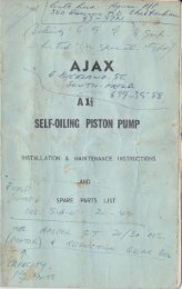
F9RREAS PTY. LTD.<br />
FORRER PAfiO PTY. LTD.<br />
MANUFAeruft,ras & DrsrRrEuroRs oF puMps FoR EVERv sERvteE<br />
I i<br />
I<br />
I
*"j<br />
{,)<br />
AUTOMATIC LUBRICATION<br />
DOUBLE ACTING<br />
HIGI"I PRESSURE<br />
EFFICIENT<br />
ECONOMICAL<br />
These are highly efficient pumps<br />
and are ideally suited for pumping<br />
over long distances and against<br />
heads up to 700 feet and over.<br />
They are positive acting with low<br />
horsepower requirement and<br />
operate silently, economically -<br />
and ef f iciently with very little<br />
ma intenance.<br />
Single Cylinder 2-Lx3<br />
Pump with Motor mounts<br />
tt<br />
it<br />
DURABLE<br />
LOW HORSEPOWER<br />
MINIMUM MAINTENANCE<br />
FULI.Y ENCLOSED<br />
GEAR DRIVE<br />
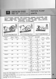
Available in Single and Duplex<br />
cylinders and having capacities<br />
up to 26,500 g.p.m. and pressures<br />
up to 300 p.s.i. Bigger<br />
pumps have large free f lowing<br />
waterways and are especially<br />
suitable for handling viscous<br />
liquids. All pumps can have the<br />
motor or engine mounted on<br />
top. thereby preserving space.<br />
Duplex Cylinder,<br />
6x8 Pump, mount3d with electric motor
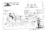
FEATURES<br />
GEAR CASE:<br />
The gear box consists of a one-piece casting which forms the base of the pump<br />
and oil reservoir. A cast iron lid encloses all working parts protecting them f rom<br />
dirt or damage, and securing safe operation. The casting is completely machined<br />
at one setting for all bearings, the cross - head, cylinder head, and shaft<br />
bearings, assuring alignment of all working parts.<br />
LUBRICATION :<br />
The pump is.entirely self-lubricating. Th.e. driving gear. carries the oil from the<br />
reservoir and distributes it to every working part of the gear case.<br />
DRIVE :<br />
Centre line drive by machine cut gear and pinion eliminates side thrust.'These<br />
are supported between wide replacable bearings.<br />
GEAR RATIO :<br />
<strong>Pumps</strong> are back geared 5 to l.<br />
I'IPING:<br />
Suction and delivery piping may be taken from either side of the pump.<br />
ROTATION :<br />
The pulley can be transferred to the opposite side of the pump from that<br />
illustrated. An eccentric cast integral with the main gear operatesthe crosshead<br />
through a connecting rod which is fitted with a replaceabie bronze bush at<br />
the crosshead end.<br />
PISTON ROD :<br />
Made of solid manganese bronze (stainless steel if required) and is fitted with<br />
Water Def lector ai a special guard against leakage fiom a loose packing box.<br />
PISTON :<br />
Comprises selected hydraulic leather cups with brass spacer and backing plates.<br />
PACKING BOX:<br />
Adjustable brass gland type .packing box of adequate depth, f itted with greasy<br />
hemp packing.<br />
CYLINDER BODY :<br />
One piece close grained casting forms the cylinder and valve chambers. This is<br />
fitted with a removable brass liner in which the piston operates.<br />
VALVES :<br />
Rubber Disc type valves with bronze seats, stems and springs are fitted to<br />
standard pumps and are all located above the cylinder. They are easily accessible<br />
for inspection, repair or replacement without disturbing pipe connections.<br />
Special valves can be supplied for specific applications.<br />
AIR CHAMBER :<br />
A cast iron air chamber is f itted as standard equipment on the discharge side of<br />
all pumps. This evens the flow of water through the pipe lines and prevents<br />
shock loads from causing damage to the pump.<br />
MOTOR MOUNTING :<br />
Cast iron slotted side rails can be supplied for mounting electric motor or<br />
petrol engine on top of the pump. This makes a compact unit and saves considerable<br />
space.
FORRERS PTY. LTD. LEAFLET F 9690<br />
POWER PUMP<br />
MODEL 2x2XL<br />
OPERATING HEADS TO 5OOfI.<br />
RELIABLE<br />
ECONOMICAL<br />
-<br />
LOW H.P.<br />
-**;ii<br />
t'l<br />
EFFICIENT<br />
LOW MAINTENANCE<br />
CAPACITY<br />
-<br />
400 G.P.H. at 600 R P"M<br />
PERFORMANCE<br />
50' I 00' 200' 250' 300' 400' 500'<br />
H.P. AT VARYING HEADS -lb h p l r+<br />
The 2x2XL FORRERS Double Acting Pump is selfoiling<br />
and has been proven a most reliable and<br />
efficient unit. lt is extremely compact as engine or<br />
electric motor can be mounted on top of pump.<br />
It is used extensively for dairying and agricultural<br />
purposes, pressure systems, domestic water supply,<br />
and for industrial high pressure service such as<br />
boiler feeding, hot water pumping, etc.<br />
Maintenance is kept to a minimum and many hours<br />
cf unattended operation can be expected<br />
2x2Xu Pump Mounted With Petrol Motor
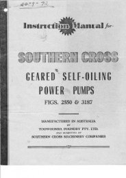
FORRERS PTY. LTD.<br />
INSTRUCTION SHEET<br />
FORRERS<br />
SELF - OILINS POWER PUMPS<br />
2*x3 PUMP WITH MOTOR MOUNT AND PULLEY<br />
INSTALLATION<br />
SITE<br />
Pump should be as close to water supply as possible. Suction lift including pipe friction<br />
should not exceed 24 feet at sea level. For each 1200 feet altitude, deduct 1 foot for practical<br />
suction lift.<br />
Should pump become flooded, drain oil fro'm crankcase, replace oil and check pump over<br />
generally.<br />
FOUNDATION<br />
lnstall pump on firm foundation, preferably concrete. Pump should be set level.<br />
SUCTION LINE<br />
Suction line should<br />
is not trapped in line.<br />
Keep suction line as<br />
Pipe diameter should<br />
lines where a large volume<br />
rise towards pump at all times. Avoid high points so as to ensure air<br />
free of bends as possible.<br />
be no sm,aller than that for which the pump is screwed. On long pipe<br />
is pumped, a size larger is pieferable.
s<br />
to<br />
INSTALLATION CONTINUED<br />
Make sure all joints are air tight.<br />
A foot valve should always be fitted where water level is below the pump. When water level<br />
higher than the pump, install a gate valve so that water may be shut off if it becomes necessary<br />
work on the pump.<br />
DISCHARGE LINE<br />
The diameter of the discharge line will depend on the work the pump has to perform, including<br />
friction in that line. The smaller the pipe ihe higher the friction load and power consumption.<br />
A check valve fitted in the discharge line as close to the pump as possible, protects the pump<br />
from water hammer and from damage through flow back of water. This also holds back this<br />
water when maintenance is being carried out on the pump.<br />
Both suction and discharge piping must be supported independently of the pump.<br />
Should a gate valve be installed in the delivery, this MUST BE OPENED before starting<br />
pLlmp. lt is always advisable in installations where a gate valve is {itied to have a relief valve<br />
between purmp and gate valve to protect pump from damage in case line is shut off or becomes<br />
blocked.<br />
GLAND PACKING<br />
Packing should be renewed periodically to protect excessive leakage from the gland and<br />
prevent damage to the piston rod. When replacing, insert each ring separately, seating it firmly<br />
and staggering ihe joints. The last ring of packing should not protrude beyond the stuffing box.<br />
lnstall the gland and tighten the nuts evenly by hand. Allow a slight leakage at all times as this<br />
is necessary to cool and lubricate the packing. Wait until the pump is running before making the<br />
final adjustment.<br />
Unduly tight packing increases power consurmption and causes wear on piston rod.<br />
PRIMING PUMP<br />
Pump can be primed by removing plug from the top of ihe suction chamber and filling the<br />
chamber and suction line completely with water. Before replacing plug, watch water level for short<br />
time to see if the footvalve is holding.<br />
, IRATION<br />
Before starting pump ensure<br />
the oil return channel. SAE 140 Oil<br />
gear case is filled with<br />
is recommended.<br />
oil to a point level with the bottom of<br />
It is advisable after the f irst<br />
place with fresh. Oil level should be<br />
48 hours of actual pumping to drain the original oil and reinspected<br />
every few months,<br />
Before starting turn the pump by hand and ensure all suction, bypass, and discharge valves<br />
are open.<br />
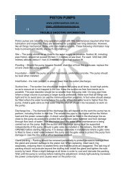
TROUBLE SHOOTTNG<br />
<strong>Piston</strong> pumps are noted for long operation periods with little more than routine lubrication<br />
and inspection. However, like all other pumps, these units can develop trouble. These are usually<br />
hydraulic troubles, or troubles connected with the installation of the complete unit. Some of these<br />
are analysed below.
PUMP DOES NOT DISCHAR,GE<br />
Suction Lift too High: At sea level a pump hand!ing water should not have a suction lift<br />
greater than 24 feet.<br />
Pump<br />
^ Not Primed: Prime pump by filling the suction line above foot valve with liquid.<br />
Open any vents on discharge side io free pump of air while filling.<br />
Suction Air Bound: Checks for leaks in suction pipe.<br />
Obstructions in Suction Line: Check suction pipe and strainer to see that they are free of<br />
rust, debris, and other obstructions<br />
Worn Parts: Worn valves, piston rod packing and piston buckets can cause a pump to lose<br />
suction. Replace as necessary.<br />
PIPING VIBR.ATES<br />
Undersize Discharge Pipe: Use a larger size of discharge line, if it is possible to change the<br />
piping. lf this cannot be done, install an air chamber in the discharge line, close to the pump.<br />
This will red'uce the pressure surges in the pipe.<br />
On Forrers Power <strong>Pumps</strong> an air chamber is supplied as standard equipment.<br />
Undersize Suction Pipe: lncrease size of piping or reduce its length. lnstall a suction air<br />
chamber close to the pump to reduce pressure surge pulsations during operation. On sizes up to<br />
and including 6in. bore x 6in. stroke this chamber is supplied.<br />
POWER END NOISY<br />
Crosshead, Bearings or Gears Worn or Loose: Check and replace as necessary.<br />
Speed ioo High: Lower pump speed to recommended level.<br />
LTQUTD END NOISY<br />
Excessive Suction Lift: This has been dealt with earlier.<br />
Gas or Air in Liquid: Inspect the suction piping for leaks at joints, around valve stems, and<br />
at other points where air can enter the system.<br />
Valve Troubles: Weak or broken springs lead to pounding of valves. Valve chatter and other<br />
noises are usually caused by operating pump at too high a speed.<br />
EXCESSIVE PACKING WEAR<br />
<strong>Piston</strong> Rod Defects: <strong>Piston</strong> rod may be worn or bent causing uneven wear of the packing.<br />
Check also for burrs on the rod. Replace badly damaged rods with new ones.<br />
POWER INPUT EXCESSIVE<br />
High Discharge Prdssure: lnspect piping for closed valve, increase in relief valve setting or<br />
.<br />
an obstruction in the piping. Where additional piping has been installed, check friction loss-has<br />
not increased the duty above the rated m.aximum head of the pump.<br />
MANUFACTURED BY<br />
Carberry Street,<br />
FORRERS PTY. LTD.<br />
lpswich, Qld.
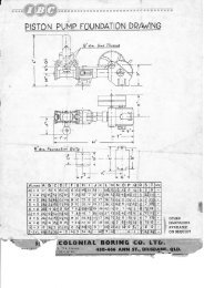
FOUNDATION DRAWINGS<br />
-<br />
STANDARD PUMPS<br />
sl<br />
o<br />
-T+_<br />
z<br />
8"5<br />
6+<br />
ct<br />
'4<br />
t3* 88<br />
6+<br />
;F o<br />
v<br />
t<br />
F<br />
I ọ<br />
t,<br />
-<br />
-td<br />
D E F G H J K L M N o P o R S T I ns.<br />
4 6 at '2 3 24 at 6i 7 3* 6<br />
3<br />
6 3* 6+<br />
6i t0+ 5 6* 34t s+ 8+ lt 27;] s* 13 3i 9 r*<br />
I<br />
2<br />
5 9<br />
6i t2+ 7 8+ 42 7 t2 t2+ 29 7* 3 r4 4i l0* r+<br />
I<br />
2<br />
si il*<br />
t0* t4+ 9 t0 53 8 t2 t7 35 7+ 6+ 6 t3+ 2<br />
I<br />
2 7 ts*<br />
t0* t4+ 9 l0 55 9 t4 l7 36 7+ 6* 5 t3* 7+<br />
I<br />
2<br />
7 ts+<br />
8 ts* 7 il+ 63+ l0i t5 t9 42 il* 6 7 t6+ 3<br />
5<br />
a 7+ t8 ,)<br />
6i t2+ 7 8* 42 7 8+ t2+ 27 7+ 13 4+ t0i t+<br />
I<br />
2<br />
q3<br />
il+<br />
t0* t4+ 9 t0 54 8+ il+ l7 38* 7+ 3* 6 t3* r+ l_ 2<br />
7 ts+ tt<br />
5<br />
I ts+ 7 il+ 62 t0 t5 t9 46 il+ 5 8+ t6+ 2+ a 7+ t8<br />
6i t0+ 6 6* 34i; (r<br />
8 ll 712 st ')r 3 .4 9 *ll<br />
I<br />
2 5 9<br />
(OTHER DIMENSIONS AVAILABLE ON REQUEST)
PUMPING TABLLJ<br />
FORRERS STANDARD PUMPS<br />
Pump<br />
N,o.<br />
Strokes ,Pump<br />
(lnches)<br />
pet Pulley Galls.<br />
Bore Stroke Suction minute R.P,M. Per Hr, sofr. loofr. l f<br />
HORSEPOWER. REQU!RED AT THESE HEADS<br />
Pulley<br />
Dia.<br />
XL<br />
(FA) 2 2 I I<br />
100 _r_<br />
300 263 4<br />
-l_<br />
-t,<br />
4 4<br />
I I<br />
3 7 3_<br />
4<br />
150 4s0 3s0<br />
,|<br />
4<br />
_l_<br />
4 i-<br />
J.<br />
2<br />
3_<br />
4 I<br />
3_ 4 4 I t+<br />
200 600 400 ,L 4 -l4 + + t 4 4 I r+<br />
9t2F<br />
(FB) 2+<br />
3 r+ l*<br />
70 350 436<br />
I<br />
4<br />
I 2 , 4 I<br />
BO 400 500 -L 4 + +<br />
3<br />
4 4<br />
12x2<br />
I<br />
l0s 525 650 + + 4 I l+<br />
9t3F<br />
(FD) 3 4 r+ r+<br />
50 250 597 -l_ 4 L a<br />
70 350 834 + r+ r+<br />
e<br />
4<br />
14 x 2+<br />
80 400 95s + t r+ r+ r+<br />
9t 4F<br />
(FF) 4 5 2 2<br />
50 250 r 300 + I ll4 ra 2 3<br />
60 300 1566 3 4 l+ loa 2+ 3 4<br />
16x4<br />
70 350 1827 I r+<br />
al<br />
L4 3 4 5<br />
9l5F<br />
(FG) 5 5 2+ 2I<br />
922F<br />
(FN) 5 6 3 3<br />
30 150 1240<br />
3_<br />
r+ ri 2<br />
50 250 2000 3 4 r* 2 3 3+<br />
65 325 2691 r* 2 3+ 4+ 6<br />
40 200 1775 1*<br />
al<br />
ZA- t 4+ s+ 6 7*<br />
50 250 2200 r+<br />
at<br />
z-2 4 5 6+ 7+ e+<br />
60 300 2675 l+ 3 4+ 6 7+ 8+ n+<br />
l6x4<br />
24x4<br />
!<br />
G g<br />
!<br />
z a<br />
-l<br />
9l6F<br />
(FJ) 6 6 3 3<br />
30 r50 2160 r+ 2 3 I<br />
50 250 3600 r+ 2+ 3+ 5 7<br />
60 300 4300 2 4 s+ 7 t0<br />
24x4<br />
E<br />
F<br />
m<br />
Vl
FORRERS. HEAVY DUTY AND HIGH PRESSURE PUMPS<br />
Pump<br />
No.<br />
(lnches)<br />
Strokes<br />
per<br />
minute<br />
Pump<br />
Pulley<br />
R.P.M.<br />
Galls.<br />
Per Hr.<br />
HOR.SEPOWER REQUTRED AT TI{ESE HEADS<br />
Bore I Stroke I Suction lDischa.ge 50ft. I 00ft. I 5oft. 200ft. 300fr. 400ft. 500ft. 600ft, 70ofr.<br />
917Ht<br />
(FC) r* 3 I 4<br />
gIBH<br />
(FE)<br />
:'-"'<br />
2* 4 r* r+<br />
9l9Hr<br />
(FH) 3 5 1+ r+<br />
94 al<br />
J2 5 l+ r+<br />
(FK) 3 6 2+ 2+<br />
92tHt<br />
(FL) 4 6 2+ L2 al<br />
923Ht<br />
(FO) 4 8 3 3<br />
924H 4+ 8 3 3<br />
(FM) 5 8 3 3<br />
60 300 170<br />
_t<br />
4<br />
BO 400 230 -t-<br />
4 + + +<br />
'I<br />
4<br />
Fulley<br />
Dia.<br />
1<br />
I<br />
4 l 2 + 4 4<br />
I<br />
12x2<br />
2 * I I r*<br />
105 525 300 + t t 4 I r* r+ r* 2<br />
40 200 260 I 4<br />
'L 4 + + +<br />
3 4 I I<br />
60 300 390 + + t * A r1- r{-<br />
BO 400 s2B + t<br />
3<br />
^1<br />
r+ r+ 2 2+<br />
40 200 560<br />
'|<br />
2 t 4 3 I r+ r+ 2+<br />
55 275 780 + 3 I r+ tz 2+ 3<br />
65 325 924 + I r+ r+ 2<br />
,)l<br />
LA 4<br />
40 200 760 -3,<br />
4 ri r+ 2.0 L4<br />
1 3+ 4+<br />
55 275 I 060 1l- ')l 2Z 3; 5 6<br />
65 325 1 250 li t; 2+ 2l<br />
J4<br />
+)<br />
A1<br />
JZ 7<br />
40 200 660 I 1 I I r+ 2 2+ 3 3i<br />
60 300 I 000 I I r+ r+ 2 3 3' 5 6<br />
70 350 I 134 I I r* lo3 2+ J2<br />
t1 4+ 5 7<br />
40 200 I 320 I I r* 2 3 4 5<br />
60 300 r 980 I r+ 2 3 4+ 6 7t<br />
70 350 2192 I 2 3 4 s+ 7+ l0<br />
30 150 I 190 I l+ r+ 2 3 4 5 6 7+<br />
40 200 I 590 I r+ 2 234 4 s+ 7 B l0<br />
60 300 2340 I 2 3 4 s+ 7+ 10 t2 15<br />
30 ls0 I 540 1+ 2 2Z 4 trl J2 7 B 7*<br />
40 200 2000 r+ 2 3 4 s+ 7+ l0 lt 12<br />
60 300 3080 r+ 3 4 5+ 7+ e+ ll+ t5 t5<br />
30 r50 I 900 l1- 2 3 4 5 7+ l0<br />
40 200 2550 l+ 2+ 3+ 4+ 6+ B+ t2<br />
50 300 3600 2 3 4 6 9 12 l5<br />
14 x2*<br />
l6x4<br />
l6x4<br />
24x4<br />
24x4<br />
30x6<br />
30x6<br />
30x6
1<br />
Pump<br />
No.<br />
Strokes Pu,mp<br />
(lnches)<br />
HORSEPOWER REQUIRED AT THESE HEADS<br />
Per Pulley Galls.<br />
Bore Stroke Suction Dischargr minute R.P.M. Per Hr. 50ft. t OOfr. I 5oft. 200ft. 300fr. 400fr. 500fr. 600ft, 7OOfr.<br />
Pulley<br />
Dia.<br />
926H1<br />
(FP) 6 8 4 4<br />
927F<br />
(rQl 7 B 4 4<br />
928F B 8 4 4<br />
929H\<br />
(FR) 5 l0 4 4<br />
930H<br />
(FS) 6 t0 4 4<br />
93I HI<br />
(FT) 7 l0 4 4<br />
932F 8 r0 4 4<br />
933F l0 r0 6 6<br />
25 125 23s0 r+ 2+ '" 4 5 7+<br />
3s 175 3250 r-a 3 / sl B+ lt<br />
55 275 4950 2 4 6 B+ 12+ l5<br />
25 125 3200 re 3 A<br />
trl<br />
J2<br />
35 17s 4500 2 4 6 7+<br />
55 :27s 6900 2 6 10 t5<br />
25 125 4200 2 3+ 5<br />
35 175 5900 2+ 5 7+<br />
45 225 7s60 3 6 l0<br />
30 r50 2300 1+ 2+ 3 4 5 7+ l0 12<br />
50 i250 3800 2 3+ 5 6J, r0 l3 l6 20<br />
40 1200 3100 r* 3 4 s+ 8+ ll r3 l5<br />
30 150 3400 r+ J 4+ 6 B+ t2 l5<br />
40 200 4600 2 4 6 8 ll+ l4 IB<br />
50 250 5700 2+ 5 7+ l0 12+ l5 20<br />
25 125 3900 2 3+ 5 6+ l0 r3 l6<br />
35 175 5500 ,2+ 5 7 8 12 14 24<br />
45 )225 7000 i3 6 B+ 12 l8 24 30<br />
25 125 4700 2 4 6 B 12<br />
35 itts 6600 3 s+ B lt l5<br />
45 i225 9440 4 8 12 l5 20<br />
20 Ir oo 6600 r3 sl o ll<br />
30 Lt 50 9900 i4 B t2+ 17<br />
40 200<br />
I 3200 r5+ l1 l5 20<br />
30x6<br />
30x6<br />
30x6<br />
Pulley<br />
to size<br />
Specified<br />
94 2+ 6<br />
al z2 2t 40 200 420<br />
TOOI| 800ft. i 900{r. r000 fr<br />
l<br />
JZ 4 4+ 5<br />
24x4
FORRERS DUPLEX PUMPS<br />
umP<br />
0Nc HES)<br />
Bore Stroke Suction Discharge<br />
PUMP PULLEY<br />
R.P.M.<br />
GALTONS<br />
PER HOUR<br />
MAXIMUM HEAD<br />
FEET<br />
MAXI,MUM<br />
H.P.<br />
934F 4 5 3 3 3s0 3600 250 7<br />
935F 5 5 3 3 325 5200 250 l0<br />
936HD 3+ 6 3 3 3s0 3300 600 l5<br />
937F 5 6 3 3 325 6400 250 l3<br />
93BHD 4 8 4 4 300 4600 600 20<br />
939HD 4+<br />
o 4 4 300 6000 500 25<br />
94OHD 5 B 4 4 300 7000 500 30<br />
94I HD 6 B 5 4 275 9800 500 40<br />
942HD 7 o I 6 6 275 r 3600 200 30<br />
943HD 8 B 6 6 225 I 5000 150 20<br />
944HD 7 t0 6 4 225 I 4000 500 50<br />
945HD B t0 B 6 225 r 8600 300 40<br />
946F l0 l0 B B 200 26500 200 30<br />
rPswrcH<br />
MANUFACTURED BY<br />
FORRERS PTY. LTD.<br />
QUEENSLA.ND
FORRERS FARTS LIST<br />
t$ll I<br />
NAME oF PARI<br />
tftLt<br />
l<br />
NAME oF PARI<br />
PART<br />
No.<br />
NAME OF PART<br />
I<br />
2<br />
3<br />
4<br />
5<br />
6<br />
7<br />
8<br />
9<br />
l0<br />
ll<br />
t2<br />
t3<br />
t4<br />
t5<br />
t6<br />
l7<br />
t8<br />
r9<br />
20<br />
2l<br />
22<br />
Gear and Eccentric Case<br />
Gear Case Lid<br />
Gear and Eccentric<br />
Connecting Link<br />
Connecfing Link Bush<br />
Retaining Ring<br />
Locking Screws Ret. Ring<br />
Locking Screw Gear Shaft<br />
Locking Nut Gear Shaft<br />
Gear Shaft<br />
Gear Shaft Bearing<br />
Pacl
FOR,RERS PARTS LIST<br />
STANDARD PUMP: MKS FB,FD' FF' FG' FJ'<br />
FK, FL, FM fO, FP, FQ,<br />
FR, F5, FT.<br />
46<br />
45<br />
44<br />
42<br />
40<br />
60<br />
l6<br />
8<br />
Gear Box ends in all F series pumps are<br />
similar in design to that shown above<br />
Only the Pump Ends (illustrated at left)<br />
differ