Instruction Manual - Godar Machinery
Instruction Manual - Godar Machinery
Instruction Manual - Godar Machinery

You also want an ePaper? Increase the reach of your titles
YUMPU automatically turns print PDFs into web optimized ePapers that Google loves.
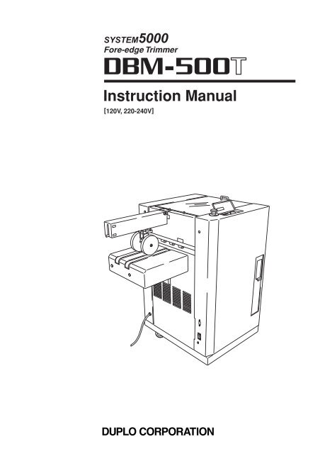
Fore-edge Trimmer<br />
<strong>Instruction</strong> <strong>Manual</strong><br />
[120V, 220-240V]
DECLARATION OF CONFORMITY<br />
DUPLO CORPORATION, located at 1-6, Oyama 4-chome, Sagamihara-shi, Kanagawa-ken 229-1180, Japan, declares that the following product,<br />
Name of product Model<br />
• Stitcher Folder, DBM-500 220-240V 50/60Hz<br />
• Trimmer, DBM-500T 220-240V 50/60Hz<br />
• Stacker, DBM-SS1 220-240V 50/60Hz<br />
• Stacker, DBM-LS1 220-240V 50/60Hz<br />
• Kicker DBM-K DC24V. Class III<br />
complies with the provisions defined by the regulations listed below.<br />
Regulation : <strong>Machinery</strong> Directive 98 / 37 / EC under EN292-1 (1991), EN292-2 (1991), prEN1010-1 (2002), prEN1010-4 (2001),<br />
EN60204-1 (1997).<br />
Low Voltage Directive 73 / 23 / EEC under IEC60950 (1999) including EN60950 (2000) deviations.<br />
Electromagnetic Compatibility Directive 89 / 336 / EEC under EN61000-3-2 (2000) , EN61000-3-3 (1995 ) + A1 : 2001.<br />
EN61000-6-2 (2001).EN61000-6-4 (2001).<br />
ÜBEREINSTIMMUNGSERKLÄRUNG<br />
Die DUPLO CORPORATION mit Sitz in 1-6, Oyama 4-chome, Sagamihara-shi, Kanagawa-ken 229-1180, Japan, versichert, daß das folgende<br />
produkt,<br />
Bezeichnung des Produkts Modell<br />
• Draht-HEFT/SCHWERT-LAGEN-FALZMASCHINE, DBM-500 220–240V 50/60Hz<br />
• BROSCHUREN FRONTSCHNEIDE-MASCHINE, DBM-500T 220-240V 50/60Hz<br />
• Papier-Glattstoss-Einrichtung, DBM-SS1 220-240V 50/60Hz<br />
• Papier-Glattstoss-Einrichtung, DBM-LS1 220-240V 50/60Hz<br />
• Zubehör teile PAPIERVORSCHUBEINHEIT, DBM-K DC24V. Class III<br />
Entspricht den Bestimmungen, wie sie durch die unten aufgeführten Vorschriften definiert sind.<br />
Vorschriften : Maschinenrichtlinie 98 / 37 / EC nach EN292-1 (1991), EN292-2 (1991), prEN1010-1 (2002), prEN1010-4 (2001), EN60204-1<br />
(1997).<br />
EWG-Niederspannungsrichtlinie 73 / 23 / EWG unter IEC60950 (1999) und EN60950 (2000).Abweichungen<br />
Richtlinie über die elektromagnetische Verträglichkeit 89 / 336 / EWG unter EN61000-3-2 (2000) EN61000-3-3 (1995)<br />
+ A1 : 2001.EN61000-6-2 (2001).EN61000-6-4 (2001).<br />
DECLARATION DE CONFORMITE<br />
DUPLO CORPORATION, située à 1-6, Oyama 4-chome, Sagamihara-shi, Kanagawa-ken 229-1180, Japon, déclare que le produit suivant ;<br />
Nom du produit Modèle<br />
• PLQUEUSE / PLIEUSE, DBM-500 220–240V 50/60Hz<br />
• ROGNEUSE, DBM-500T 220-240V 50/60Hz<br />
• Empileuse, DBM-SS1 220-240V 50/60Hz<br />
• Empileuse, DBM-LS1 220-240V 50/60Hz<br />
• accessoire EJECTEUR DBM-K DC24V. Class III<br />
est conforme aux dispositions définies par les réglementations suivantes ;<br />
Réglementations : Directive sur les machines 98 / 37 / EC en application de EN292-1 (1991), EN292-2 (1991), prEN1010-1 (2002), prEN1010-4<br />
(2001), EN60204-1 (1997).<br />
Directive sur la basse tension 73 / 23 / EEC en application de IEC60950 (1999) et EN60950 (2000) derogations.<br />
Directive de compatibilité électromagnétique 89 / 336 / EEC d’après EN61000-3-2 (2000) EN61000-3-3 (1995)<br />
+ A1 : 2001.EN61000-6-2 (2001).EN61000-6-4 (2001).<br />
DICHIARAZIONE DI CONFORMITÁ<br />
DUPLO COPRORATION sita a 1-6, Oyama 4-chome, Sagamihara-shi, Kanagawa-ken 229-1180, Japan, dichiara che il seguente prodotto,<br />
Nome del prodotto Modello<br />
• Rilegatrice, DBM-500 220-240V 50/60Hz<br />
• Regolatore, DBM-500T 220-240V 50/60Hz<br />
• Impilatore, DBM-SS1 220-240V 50/60Hz<br />
• Impilatore, DBM-LS1 220-240V 50/60Hz<br />
• Estrattore, DBM-K DC24V. Class III<br />
è conforme ai requisiti definiti dalle norme sotto elencate.<br />
Direttiva Bassa Tensione : Direttiva sui macchinari 98 / 37 / CE in base a EN292-1 (1991), EN292-2 (1991), prEN1010-1 (2002), prEN1010-4<br />
(2001), EN60204-1 (1997).<br />
Direttiva relativa alle apparecchiature a bassa tensione 73 / 23 / CEE in base a IEC60950 (1999) incluso EN60950<br />
(2000) deviazioni.<br />
Direttiva EMC 89 / 336 / CEE in base a EN61000-3-2 (2000) EN61000-3-3 (1995) + A1 : 2001.EN61000-6-2<br />
(2001).EN61000-6-4 (2001).<br />
En<br />
Ge<br />
Fr<br />
It
DECLARACIÓN DE CONFORMIDAD<br />
DUPLO CORPORATION, con domicilio en 1-6, Oyama 4-chome, Sagamihara-shi, Kanagawa-ken 229-1180, Japan, declara que el producto<br />
siguiente,<br />
Nombre del producto Modelos<br />
• Realizador de folletos dinámico, DBM-500 220-240V 50/60Hz<br />
• Cortadora, DBM-500T 220-240V 50/60Hz<br />
• Apilador, DBM-SS1 220-240V 50/60Hz<br />
• Apilador, DBM-LS1 220-240V 50/60Hz<br />
• Desplazadora, DBM-K DC24V. Class III<br />
Cumple las disposiciones definidas por las siguientes reglamentaciones.<br />
Reglamentaciones : Directiva 98 / 37 / CE sobre máquinas bajo EN292-1 (1991), EN292-2 (1991), prEN1010-1 (2002), prEN1010-4 (2001),<br />
EN60204-1 (1997).<br />
Directiva sobre baja tensión 73 / 23 / CEE bajo IEC60950 (1999) incluyendo las derogaciones EN60950 (2000).<br />
Directiva sobre CEM89 / 336 / CEE bajo EN61000-3-2 (2000) EN61000-3-3 (1995) + A1 : 2001.EN61000-6-2<br />
(2001).EN61000-6-4 (2001).<br />
Applicable to the 120 V machine<br />
This equipment has been tested and found to comply with the limits for a Class A digital device, pursuant to Part 15 of the FCC<br />
Rules.<br />
These limits are designed to provide reasonable protection against harmful interference when the equipment is operated in a<br />
commercial environment.<br />
This equipment generates, uses, and can radiate radio frequency energy and, if not installed and used in accordance with the<br />
instruction manual, may cause harmful interference to radio communications.<br />
Operation of this equipment in a residential area is likely to cause harmful interference in which case the user will be required<br />
to correct the interference at his own expense.<br />
Sp
INTRODUCTION<br />
Thank you for purchasing this Duplo equipment. To ensure correct usage, please read this<br />
instruction manual thoroughly, especially the section entitled "Safety Precautions".<br />
The aim of this instruction manual is to ensure safe and proper use of the equipment.<br />
For this reason, do not attempt to remodel, modify or adapt this equipment or to use it for any<br />
other purpose than that intended by the manufacturer.<br />
After reading, please keep this instruction manual handy for future reference.<br />
CONTENTS<br />
1. SAFETY PRECAUTIONS ............................................................................................................2<br />
2. USAGE PRECAUTIONS ..............................................................................................................5<br />
2-1. Power Supply .....................................................................................................................5<br />
2-2. Operating Environment .......................................................................................................5<br />
2-3. Storage Conditions .............................................................................................................5<br />
3. NAMES AND FUNCTIONS ..........................................................................................................6<br />
3-1. External Parts .....................................................................................................................6<br />
3-2. Internal Parts ......................................................................................................................7<br />
3-3. Belt Stacker (Optional) .......................................................................................................8<br />
4. NAMES AND FUNCTIONS OF CONTROL PANEL ....................................................................9<br />
5. PREPARING FOR BINDING ......................................................................................................10<br />
5-1. Power ON .........................................................................................................................10<br />
5-2. Using the Belt Stacker ......................................................................................................11<br />
6. CORRECTING PAPER JAMS ...................................................................................................12<br />
7. IF TRIMMING IS SKEWED ........................................................................................................13<br />
8. ERROR MESSAGES .................................................................................................................14<br />
8-1. When Paper Jams ............................................................................................................14<br />
8-2. Other Error Messages ......................................................................................................14<br />
9. USING WITH DBM-LS1, DBM-K (OPTIONAL) .........................................................................15<br />
10. CLEANING .................................................................................................................................17<br />
11. SPECIFICATIONS ......................................................................................................................18<br />
1
2<br />
1. SAFETY PRECAUTIONS<br />
Always observe the cautions and warnings given below to prevent personal injury or property<br />
damage.<br />
The degree of danger and damage that could occur is indicated on two levels by the<br />
following marks.<br />
WARNING: Ignoring this mark could result in the possibility of serious injury<br />
or even death.<br />
CAUTION: Ignoring this mark could result in the possibility of injury or<br />
physical damage.<br />
The following graphic symbols indicate the various types of action to be performed<br />
or avoided.<br />
This graphic symbol indicates a forbidden action.<br />
means “Do not disassemble.”<br />
means “Do not touch.”<br />
This graphic symbol indicates actions that must be performed.<br />
means “Disconnect the power plug.”<br />
WARNING:<br />
Do not put your hands under the blade when correcting paper jams of the trimming<br />
section. There is danger of cutting off your fingers.<br />
Do not place metal objects or vessels containing liquids on top of the unit. The entry of<br />
any metal object or liquid could result in a fire or an electrical shock.<br />
Do not insert any metal or easily-combustible object inside this unit. This could result in<br />
a fire or an electrical shock.<br />
Do not touch or insert foreign objects into any rotating part during operation. This could<br />
result in injury.<br />
Do not remove the cover or back panel. This unit contains high-voltage components that<br />
could cause an electrical shock.<br />
Do not disassemble, modify or repair this unit. There is a danger of fire, electrical shock<br />
or injury. Contact your dealer when repairs are necessary.<br />
Use only the power supply voltage specified on the main nameplate. Using other<br />
voltages could result in a fire or an electrical shock.
1. SAFETY PRECAUTIONS<br />
Keep this unit and the power cord away from heaters and heater vents. Excessive heat<br />
could melt the cover or power cord covering, and result in a fire or an electrical shock.<br />
Do not use flammable sprays or solvent inside or near the unit (e.g. when cleaning the<br />
unit).<br />
Such flammable gas or solvent may ignite and cause a fire or combustion.<br />
Make sure that the combined power consumption of the appliances to be connected<br />
does not exceed the capacity rating of the power outlets or plug receptacles. Exceeding<br />
the capacity rating could cause the power outlets, plug receptacles, or power extension<br />
cords to overheat and catch a fire.<br />
Remove any dust that accumulates on the power plug prongs and the surface of the plug<br />
from which the prongs extend. Accumulated dust could result in a fire.<br />
If any foreign object such as metal or liquid should enter this unit, immediately turn the<br />
unit off at the power switch and disconnect the power plug from the power outlet. Failure<br />
to do so could result in a fire or an electrical shock. Contact your dealer immediately.<br />
Do not damage the power cord or power plug. (Do not scratch, alter, bend, twist, pull or<br />
place heavy objects on the power cord or power plug.)<br />
This could result in damage, a fire or an electrical shock.<br />
Always grip the plug when disconnecting the power plug from the power outlet. Forcibly<br />
pulling on the power cord could cause damage, resulting in a fire or an electrical shock.<br />
Do not touch the power plug or power switch with wet hands. This could result in an<br />
electrical shock.<br />
Before cleaning this unit, turn the unit off at the power switch and disconnect the power<br />
plug from the power outlet. Accidental operation of the unit during cleaning could result<br />
in injury.<br />
3
4<br />
1. SAFETY PRECAUTIONS<br />
Do not touch blades.<br />
It could cause serious<br />
injury.<br />
Safety<br />
The following shows where warning and caution labels are pasted and location of the safety switch.<br />
Note<br />
Top cover<br />
Do not use inflammable<br />
gas or solvent<br />
inside unit.<br />
It could cause fire<br />
or combustion.<br />
Emergency stop switch<br />
Waste bin<br />
Warning and caution labels are pasted to ensure the safety of users. Do not remove nor change them. Should a label become<br />
dirty or missing, be sure to contact your dealer for a new one.<br />
The control panel and emergency stop switch may be moved opposite to the location shown in the above figure.
2. USAGE PRECAUTIONS<br />
2-1. Power Supply<br />
• This equipment shall be installed near the socket-outlet where the plug on the power<br />
supply cord is easily accessible.<br />
• Make sure the power supply used is always within the following range.<br />
220-240V AC 50Hz/120V AC 60Hz<br />
• When you power other appliances from the same AC outlet, make sure that the combined<br />
power consumption does not exceed the power supply capacity.<br />
Rated power of this equipment : 3.3A/5.4A<br />
2-2. Operating Environment<br />
Operate this unit in the following environment:<br />
• where the temperature range is between 5 and 35°C/41 and 95°F,<br />
• where the humidity range is between 10 and 85%RH (no dew condensation),<br />
• which is not subject to direct sunlight,<br />
• which is subject to little or no vibration,<br />
• where there are no harmful chemicals,<br />
• which is reasonably free from dust,<br />
• which is free from air-borne salt, and<br />
• where the equipment will not be exposed to water.<br />
2-3. Storage Conditions<br />
Store this unit in the following environment:<br />
• where the temperature range is between –10 and +50°C/14 and 122°F,<br />
• where the humidity range is between 10 and 85%RH (no dew condensation),<br />
• which is not subject to direct sunlight,<br />
• which is subject to little or no vibration,<br />
• where there are no harmful chemicals,<br />
• which is reasonably free from dust,<br />
• which is free from air-borne salt, and<br />
• where the equipment will not be exposed to water.<br />
5
6<br />
3. NAMES AND FUNCTIONS<br />
bl<br />
4<br />
3<br />
bm<br />
bn<br />
bo<br />
bp<br />
bk<br />
3-1. External Parts<br />
No. Name Function<br />
1 Belt stacker Feeds the trimmed booklets to the stacker plate.<br />
Connect the power cord plug of the Belt Stacker Unit to the outlet of the DBM-500T.<br />
2 Stacker plate Receives booklets. Normally use it at lower position.<br />
When stacked poor due to small booklet size, use it at upper position.<br />
3 Belt stacker power outlet Connects the power cord of the belt stacker.<br />
4 Kicker connector Connects the connecting cable of DBM-K (kicker) (optional).<br />
5 Top cover Safety cover<br />
6 Control panel Displays instructions for operating the machine and messages.<br />
7 Waste bin Paper offcuts of trimmed paper are ejected here.<br />
8 Power switch Refer to “5-1. Power ON” ( Refer to page 10)<br />
9 Remote switch Refer to “5-1. Power ON” ( Refer to page 10)<br />
bk Power cord Supplies power to this machine.<br />
bl Paper guide wheel Holds booklets ejected to the stacker, and feeds them to the stacker plate.<br />
bm E port connector-1 Connects the E port cable from the upstream unit.<br />
bn E port connector-2 Connects the E port cable to the downstream unit.<br />
bo D port connector-1 Connects the D port cable from the upstream unit.<br />
bp D port connector-2 Connects the D port cable to the downstream unit.<br />
1<br />
2<br />
9<br />
5<br />
8<br />
6<br />
7
1<br />
3-2. Internal Parts<br />
2<br />
3. NAMES AND FUNCTIONS<br />
No. Name Function<br />
1 Emergency stop switch • Stops the machine in emergency.<br />
To stop the machine normally, use the Stop key on the upstream unit.<br />
• To release this switch, rotate it to the right.<br />
2 Stopper unit Moves according to the paper size.<br />
3 Blade Trims the fore-edge.<br />
4 Auxiliary roller C lever Adjust this when running small size booklets.<br />
Remove the infeed roller unit to adjust it.<br />
5 Conveyance roller Adjust according to the number of pages.<br />
5<br />
4<br />
5<br />
3<br />
5<br />
7
8<br />
3. NAMES AND FUNCTIONS<br />
1<br />
3-3. Belt Stacker (Optional)<br />
2<br />
DBM-500T<br />
No. Name Function<br />
1 DBM-LS1 (Long stacker) Conveys booklets. (Optional)<br />
2 DBM-K (Kicker) Pushes a booklets out at every desired number to make batches of booklets. (Optional)<br />
Applicable to the short belt stacker. (SS-1)
4. NAMES AND FUNCTIONS OF<br />
CONTROL PANEL<br />
LCD<br />
Displays the number of processed booklets and various messages.<br />
Eject button<br />
Forcibly ejects paper.<br />
Jog dial<br />
For selecting menus.<br />
Press the center to select and confirm items.<br />
Clear button<br />
Clears the counter to 0.<br />
Stopper button<br />
Returns the stopper to its initial position.<br />
Power indicator<br />
Lights up when the power is<br />
turned ON.<br />
Button B<br />
If the blade is locked and does not<br />
recover with button A, press this<br />
button to return the blade.<br />
Button A<br />
If the blade was stopped halfway<br />
through operations (emergency stop,<br />
etc.), press this button to return it to its<br />
original position.<br />
9
10<br />
5. PREPARING FOR BINDING<br />
DBM-500T operates according to the operations set at DBM-500.<br />
All adjustments of the stopper position, etc. are performed on the DBM-500 control (touch) panel.<br />
For details, refer to the instruction manual for 500.<br />
This machine has a power switch and remote switch.<br />
Turn On the power switch, and set the remote switch to<br />
" ".<br />
As the power of this machine is turned On/Off together<br />
with the power switch of the upstream unit by the remote<br />
function, there is no need to turn On and Off these two<br />
switches for this machine.<br />
Note<br />
����� To turn the power of this machine On/Off by<br />
itself, set the remote switch to " I " and the<br />
power switch to On.<br />
����� When operating the remote switch, do so after<br />
turning Off the power switch.<br />
����� If an upstream unit is connected, do not turn<br />
On/Off the power of this machine by itself.<br />
This may cause the machine to operate<br />
abnormally.<br />
Be sure to turn On/Off the power switch of the<br />
upstream unit instead.<br />
5-1. Power ON<br />
Remote switch Power switch
Be sure to use the standard belt stacker of DBM-500.<br />
Once the binding method has been set at DBM-500, the<br />
paper guide wheel will move according to the finished<br />
length.<br />
Press the stopper button to return the stopper to its initial<br />
position.<br />
Adjust the center of the paper guide wheel to the triangular<br />
mark.<br />
Loosen knobscrew A, rotate the disc nut, and move the<br />
paper guide wheel. Adjust knobscrew A to the disc nut<br />
hole, and tighten.<br />
� If the finished size of the booklet is less than 121 mm/<br />
4.76 inch, replace the paper guide wheel with the one<br />
for small size.<br />
To replace, loosen knobscrew B, and remove the paper<br />
guide wheel to replace.<br />
When mounting, tighten knobscrew B at the cut-away.<br />
� Set the driving time of the conveyance belt according to<br />
the finished size of the booklet. For details on setting,<br />
refer to the instruction manual for DBM-500 (“ Setting<br />
the Stacker ” on page 57).<br />
5-2. Using the Belt Stacker<br />
Disc nut<br />
Triangular mark<br />
Paper guide wheel<br />
Knobscrew B<br />
Cut-away<br />
5. PREPARING FOR BINDING<br />
Knobscrew A<br />
Paper guide wheel<br />
Paper guide wheel<br />
Knobscrew B<br />
11
12<br />
6. CORRECTING PAPER JAMS<br />
11111 When paper jams, a message will be<br />
displayed on the control panel. (For details<br />
of messages, refer to “8-1. When Paper<br />
Jams”.)<br />
22222 Open the top cover, and remove the<br />
jammed paper.<br />
Note<br />
The machine will not operate if the top cover<br />
is not closed back properly.<br />
Top cover
7. IF TRIMMING IS SKEWED<br />
When the booklet is trimmed before it touches the stopper completely<br />
There is a need to adjust the driving time of the conveyance belt. Adjust this driving time on the touch panel of<br />
DBM-500.<br />
Adjusting the driving time of the conveyance belt<br />
11111 Select the accessory menu on the touch panel of DBM-500.<br />
Next, press “Forth key” to display the following screen.<br />
MAINMENU ADJUST OPTION ACCESSOR<br />
207. 0<br />
22222 To decrease the driving time, press the " key". To increase the time, press the " key".<br />
If the booklet is trimmed before it touches the stopper completely, resulting in skewed finishing, increase the driving<br />
time so that the booklet is trimmed after it completely touches the stopper.<br />
If the booklet is still trimmed skewed after the above adjustments, adjust the angle of the stopper as necessary.<br />
33333 Loosen the two knobscrews at the top of the stopper unit. (Rotate by one to two turns to the left.)<br />
44444 Adjust the angle of the unit using the side<br />
screw.<br />
The angle of the unit changes as shown in the<br />
figure according to the direction of rotation.<br />
55555 After adjusting the angle, tighten the<br />
knobscrews.<br />
66666 Trim the booklets and check.<br />
77777 Repeat this adjustment until the desired<br />
trimming is achieved.<br />
Side screw<br />
Knobscrews<br />
Stopper unit<br />
13
14<br />
8. ERROR MESSAGES<br />
8-1. When Paper Jams<br />
When paper jams, the LCD shows [Paper Jam] on the first line and a message on the second line.<br />
2nd line message Description Solution<br />
Jam-01 Entrance Paper jam in front of the entrance Remove the jammed booklet.<br />
Jam-01 Delivery Paper jam near the trimming area Remove the jammed booklet.<br />
Jam-02 Entrance Paper jam at the entrance Remove the jammed booklet.<br />
Jam-02 Delivery Paper jam at the delivery unit Remove the jammed booklet.<br />
8-2. Other Error Messages<br />
1. When the machine has been stopped by the emergency stop switch, the LCD shows [Emergency stop] on the first line<br />
and a message on the second line.<br />
2nd line message Description Solution<br />
(Blank) The emergency stop switch of this machine has been<br />
pressed.<br />
Release the switch.<br />
Upstream The emergency stop switch of the upstream unit has<br />
been pressed.<br />
Release the switch.<br />
Downstream The emergency stop switch of the downstream unit<br />
has been pressed.<br />
Release the switch.<br />
2. When the following errors occur, the LCD shows a message on the second line.<br />
2nd line message Description Solution<br />
Scrap Box Full The waste bin is full. Remove the paper offcuts.<br />
Top Cover Open<br />
(Safety cover)<br />
The top cover is open. Close the top cover completely.<br />
See Scrap Box The waste bin is not set properly. Set the waste bin properly.<br />
Guide roller The paper guide wheel is not set at the correct<br />
position.<br />
Adjust the paper guide wheel to the proper position.<br />
No kicker The kicker is not attached. Attach the kicker.<br />
RL VP1 error Electrical error • Open/close the top cover to clear the error.<br />
• Check that the waste bin is set properly.
9. USING WITH DBM-LS1, DBM-K (OPTIONAL)<br />
DBM-LS1 and DBM-K are options.<br />
11111 Perform the setting of DBM-K at DBM-500.<br />
For details on setting, refer to the instruction<br />
manual for DBM-500.<br />
22222 Set a desired number of booklets per<br />
batch.<br />
For details on setting, refer to the instruction<br />
manual for DBM-500.<br />
33333 Adjust the position of the paper guide<br />
wheel.<br />
Adjust to the position of “finished length +A mm/<br />
A inch”.<br />
Length of A for A4 paper<br />
Paper<br />
quality<br />
Fine quality<br />
paper<br />
Coated<br />
paper<br />
Two<br />
20 to 40 mm/<br />
0.79 to 1.57<br />
inch<br />
20 to 30 mm/<br />
0.79 to 1.18<br />
inch<br />
44444 Place the stopper.<br />
Number of sheets<br />
Stopper<br />
Ten<br />
60 to 70 mm/<br />
2.36 to 2.76<br />
inch<br />
40 to 50 mm/<br />
1.57 to 1.97<br />
inch<br />
Twenty<br />
70 to 90 mm/<br />
2.76 to 3.54<br />
inch<br />
60 to 80 mm/<br />
2.36 to 3.15<br />
inch<br />
Set longer for large paper, and shorter for smaller paper.<br />
Paper guide wheel DBM-500T<br />
DBM-LS1<br />
Finished length +A<br />
Booklet width<br />
+ 45 to 55 mm<br />
(+1.77 to 2.17 inch)<br />
Stopper<br />
Booklet<br />
15
16<br />
9. USING WITH DBM-LS1, DBM-K (OPTIONAL)<br />
55555 Using the under guide.<br />
To sort booklets less than 180 mm/7.09 inch in use the under guide provided.<br />
� Place the guide as shown below close to the L side belt. Do not have them touched each other.<br />
66666 Start operations.<br />
� The ejected booklets are sorted according to the<br />
value set.<br />
� If sorting is inadequate, move the paper guide<br />
wheel to the stacker plate.<br />
� In the following cases, move the paper guide<br />
wheel to the delivery outlet or set the<br />
conveyance belt driving time longer. (Refer to<br />
DBM-500 instruction manual, "Setting the<br />
Stacker" on page 57.)<br />
1 When the fore-edge of booklets opens, and<br />
the alignment is poor.<br />
2 When booklets stop after delivery to the<br />
stacker.<br />
� When not using the kicker, move the kicker<br />
shown in the figure.<br />
Note<br />
DBM-K<br />
� Numerical data are memorized even if the<br />
power is turned off.<br />
� The minimum booklet size for kicker is 120<br />
mm/4.72 inch x 120 mm/4.72 inch.<br />
R side belt<br />
DBM-500T<br />
Guide<br />
L side belt<br />
DBM-LS1<br />
Loosen the knobscrew<br />
Move the kicker and<br />
loosen the knobscrew
10. CLEANING<br />
To ensure safety, be sure to turn OFF the power before cleaning.<br />
∗ Cleaning the conveyance belt<br />
� Wipe with a cloth moistened with alcohol.<br />
After cleaning, prior to turning On the power, make sure that the alcohol has volatilized and dried completely.<br />
∗ Cleaning the sensor<br />
� Wipe off dusts on the sensor of the stopper unit and delivery unit.<br />
Conveyance<br />
belt<br />
Stopper unit<br />
Delivery unit sensor<br />
Conveyance belt<br />
Delivery unit sensor<br />
[Delivery unit]<br />
Conveyance belt<br />
Stopper unit sensor<br />
Conveyance belt<br />
17
18<br />
11. SPECIFICATIONS<br />
DBM-500T<br />
Name<br />
Model<br />
Paper size<br />
Paper quality<br />
Maximum processing<br />
speed<br />
Trimming method<br />
Trimming performance<br />
Finished length<br />
Trimming length<br />
Noise<br />
Power supply, consumption<br />
power, current<br />
Machine size<br />
Weight<br />
GSM : g/m 2<br />
DBM-500T<br />
Fore-edge trimmer<br />
Length (Before trimming) 85 to 250 mm / 3.35 to 9.84 inch<br />
Width 120 to 356 mm / 4.72 to 14.02 inch<br />
Fine quality paper, art paper, coated paper<br />
Fine quality paper 64 to 127.9 GSM / 17 to 33 lb<br />
Art, coated paper 84.9 to 157 GSM / 24 to 41 lb<br />
4,500 sets/hour (fine quality paper 81.4 GSM / 22 lb), 10 sheets A4, Letter saddle-stitched booklet<br />
3,900 sets/hour (fine quality paper 81.4 GSM / 22 lb), 10 sheets A3, Ledger saddle-stitched booklet<br />
Top / bottom two-blade<br />
Equivalent to 50 sheets x 81.4 GSM / 22 lb<br />
75 to 250 mm / 2.95 to 9.84 inch<br />
1- 25 mm / 0.04-0.98 inch<br />
Up to 75 mm / 2.95 inch for less than 12 sheets depending on quality and size<br />
78 dB (Including peak, A scale)<br />
220-240 V 50 Hz 3.3A / 120V 60 Hz 5.4A<br />
635 (W) x 700 (D) x 1094 (H) mm / 25.00 (W) x 27.56 (D) x 43.07 (H) inch (Including body)<br />
241 kg / 531.3 lb (Including accessories)<br />
Specifications and external view are subject to change without prior notice for improvements.
DBM-K (Kicker) (Optional)<br />
Name<br />
Size<br />
Weight<br />
DBM-K<br />
80 (W) x 206 (D) x 256 (H) mm / 3.15 (W) x 8.11 (D) x 10.08 (H) inch<br />
2.5 kg / 5.5 lb<br />
DBM-LS1 (Long stacker) (Optional)<br />
Name<br />
Size<br />
Weight<br />
DBM-LS1<br />
1369 (W) x 384 (D) x 816 (H) mm / 53.90 (W) x 15.12 (D) x 32.13 (H) inch<br />
When DBM-K is mounted<br />
1369 (W) x 670 (D) x 970 (H) mm / 53.90 (W) x 26.38 (D) x 38.19 (H) inch<br />
* When DBM-500T is connected, the depth will be 748 mm / 29.4 inch.<br />
35 kg / 77.2 lb<br />
11. SPECIFICATIONS<br />
19
12K-90020-03100020S-0